

StarWind Virtual SAN Scale-Out Architecture
- September 17, 2015
- 26 min read
INTRODUCTION
This document reveals StarWind’s approach to Scale-Out architecture and the

ways of its implementation. It also contains the basic details on StarWind Virtual SAN, a software defined storage solution with unlimited scale-out capabilities. Using it as an example, the technical paper provides a comprehensive insight into best practices of virtual shared storage deployment and scaling. Scale-out has been proven the way to go in virtualized environments, so learning the way to perform it right is the key to growing your deployment without any issues.
The technical paper is aimed at experienced virtualization admins and StarWind users, who want to implement scale-out architecture into their deployments.
A full set of up-to-date technical documentation can always be found here, or by pressing the Help button in the StarWind Management Console.
For any technical inquiries, please visit our online community, Frequently Asked Questions page, or use the support form to contact our technical support department.
Hyper-Converged Storage
StarWind Virtual SAN is a software defined storage solution designed to run on top of Microsoft Windows operating systems and any commodity server hardware making it an excellent substitute for expensive proprietary SAN hardware. One of the most trending scenarios is running StarWind as a storage foundation for a hyper-converged clustered virtualization platform. In this case StarWind is installed on the same hardware with the hypervisor, either in the Microsoft Server OS parent partition, or as a VM on top of the hypervisor. This scenario completely eliminates the need in any type of dedicated shared storage hardware. Instead, the DAS of any cluster node is joined into a unified resource pool, which is shared to the entire cluster providing it with fast, reliable, and redundant shared storage.
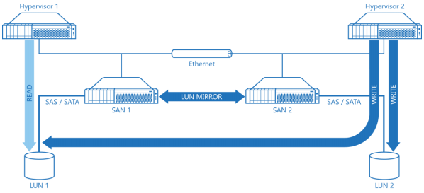
Diagram 1. Classic HA SAN Architecture.
Diagram 1 illustrates a “compute and storage separated” highly-available SAN architecture. Direct attached storage (LU 1 and 2) is connected to SAN 1 and 2 appropriately. A virtual disk created by mirroring LU 1 and2 is then connected to the Hypervisor cluster (Hypervisor 1 and 2). This approach has been used for years and despite all the deployment benefits it also introduces a set of the major drawbacks:
1. It’s expensive since minimum of four physical servers are required. Redundant networking equipment is required as well to fulfill the Fault Tolerance requirements.
2. This architecture is comparably slow because all IO to the shared storage is first packed into iSCSI commands, then transmitted through Ethernet to be then unpacked for local processing by SAS/SATA storage on the SAN servers. The READ requests first go down the Ethernet fabric from Hypervisor to the SAN node. In the SAN each request is unpacked and sent down to SAS/SATA layer where it reaches the actual LU to fetch the data. After that it has to get the data back using same path and thus, same number of hops and “repackaging stations”. All writes get doubled because we need to keep content of both LUs coherent, and go down the same path as READ except they also have an extra network hop caused by synchronization. This one appears when one of the SAN nodes transmits a WRITE command to the second node to keep LUs synchronized (LUN MIRROR arrow on the Diagram 1).
3. The cache performance and thus, its effectiveness is significantly limited. There are 2 possible scenarios:
• Cache is located directly on the SAN nodes. In this case very fast cache is accessed by the hypervisor over a comparably slow Ethernet link which introduces a significant performance bottleneck..
• Cache is partially located on the hypervisor nodes. In this case it is not synchronized between the SAN and hypervisor nodes. As a result, cache can only accelerate reads, and if a VM or application is moved between hypervisor nodes it experiences performance loss and latency increase since its cache remains pinpointed on the other hypervisor node.
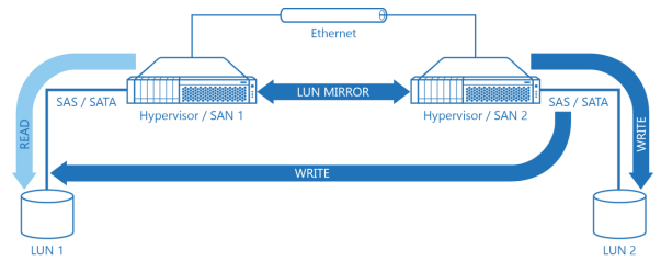
Diagram 2. Virtual SAN Architecture.
Diagram 2 illustrates a hyper-converged Virtual SAN architecture. Each Server is now running both hypervisor and storage software, DAS called LUN is attached directly to hypervisor nodes which are also running virtual SAN software so now they are called Hypervisor / SAN nodes. Virtual SAN architecture has a multiple benefits compared to the “Compute-and-storage separated” approach:
1. Amount of servers, networking equipment, and corresponding OpEx for the whole infrastructure is reduced more than twice.
2. Performance is better compared to any dedicated shared storage scenario. READ goes directly to the servers DAS over a high performance and low latency SAS or SATA interconnect. Reads virtually never touch Ethernet unless DAS on a given Hypervisor / SAN node has failed. Red WRITE goes directly to DAS over SAS/SATA on the node, which currently owns the LUN and needs to go through Ethernet only once compared to the doubled amount of network hops in a “compute-and-storage-separated” scenario.
3. Cache is 100% local. In case of hyper-converged scenario all cache layers reside either on extremely fast system bus like it’s a case with RAM, or on local PCI Express bus when thinking about PCI-E attached flash storage. In this scenario cache is not bottlenecked by low performance and high latency Ethernet fabric like it is in the ”compute-and-storage separated” scenario.
Hyper-converged scenario has only one theoretical drawback which is resiliency to number of nodes went down. With a four node minimal fault tolerant compute-and-storage-separated scenario, hypervisor cluster can survive if two nodes have failed. So one of the hypervisor nodes can break and at the same time one of the storage nodes can stop responding, leaving 1 hypervisor node and one SAN node in service which is enough to keep the cluster operational.
However, traditional configuration can sustain 2 failures at a time only if it’s one SAN node and one cluster node failing at a time. If 2 hypervisor nodes or 2 SAN nodes fail at the same time – whole cluster is dead. In other words, traditional configuration can sustain 50 % of 2 node failures.
There are only two nodes total in the minimal hyper-converged cluster design so it can obviously survive only one node failure. However, there’s a way not only to improve this but actually get hyper-converged hypervisor cluster design which is still faster, more cost effective, and provides better fault tolerance compared to compute-and-storage-separated scenario. This design is 3-way replication or triplication when mission-critical components are not doubled but actually tripled.
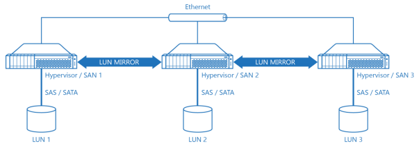
Diagram 2a. Hyper-Converged Architecture with 3-Way Replication or Triplication.
Diagram 2a features a schematic drawing of a hyper-converged cluster using 3-way replication. Proposed design is faster in terms of compute power, since now three nodes run virtual machines versus two in a traditional compute-and-storage-separated scenario so proposed hyper-converged scenario offers both better performance and load balancing. Also, proposed scenario has lower TCO and implementation cost compared to compute-and-storage-separated scenario because it uses combined hypervisor/SAN node approach instead of a noninterchangeable node approach in the compute-and-storage-separated scenario.
The 3-Node cluster is also faster in terms of I/O, which, along with already mentioned local I/O majority and local fast cache, make hyper-converged approach an optimal configuration for any virtualization environment. Virtual SAN does bounded I/O as we’ll see later.
3-Node Cluster hyper-converged cluster makes all participating nodes equal thus, in the event of failure cluster remains operational even with a single server left. This gives 3-nodeconfiguration much better fault tolerance compared to the traditional 4-node compute-and-storage-separated configuration.
Why it matters where your data is in the cluster
Unlike VMware, Microsoft doesn’t have a real clustered FS like VMFS. For the customer this means that only one hypervisor cluster node from the whole cluster can be the owner of a particular LUN in a given moment. Other cluster nodes have to either wait for the owner node to return ownership of the LUN or use a workaround called “redirected access” which is an option but it causes part of the I/O to go over Ethernet to the LUN owner node.
This dramatically decreases I/O throughput and whole cluster bandwidth and performance.
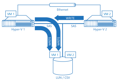
Diagram 3. Sample Hyper-V Cluster with a Shared SAS LUN in a Redirected I/O Mode.
Diagram 3 shows sample 2-node Hyper-V cluster with a LUN shared over SAS fabric and a Clustered Shared Volume on top of it. For simplicity, non-redundant storage configuration is selected. However, with highly available storage setup everything would be the same. Both VM1 and VM2 are hosted on a shared LUN / CSV. VM1 runs on the first hypervisor node and VM2 runs on the second hypervisor node. Only one cluster node is the owner of the CSV. First VM accesses storage over high performance and low latency SAS bus however, second hypervisor node has to use redirected access and route I/O over lower performance and higher latency Ethernet link first, then get I/O processed and redirected by the CSV owner via actual SAS fabric to the LUN where I/O is carried out. It is then fetched to second Hyper-V node. This process is Hyper-V specific and its complexity and design prevents Hyper-V from providing good performance for the whole cluster.
However, redirected I/O is not a killer on its own. Even if the hypervisor has a real clustered file system and underlying hardware does offload LUN “lock and release”, hypervisor nodes still need to fight for a shared storage resource, which results in LUN owner being changed on a routine basis.
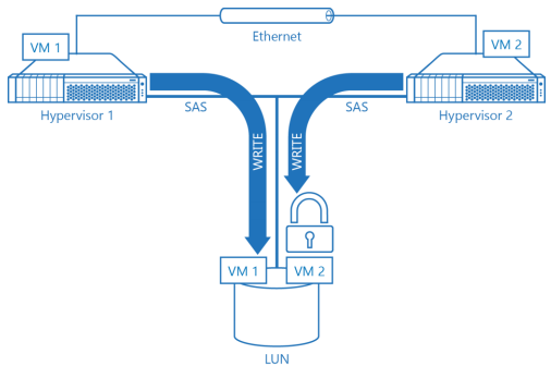
Diagram 4. Sample Hypervisor Cluster with Nodes Fighting for LUN.
Diagram 4 illustrates sample hypervisor cluster using two hypervisor nodes and a single nonredundant storage source(LUN) for simplicity. Both nodes are fighting for a shared LUN. Both VM1 and VM2 are hosted on the same LUN. First hypervisor node is hosts VM1, and second – VM2. First hypervisor node is the owner of the shared LUN and has full access, second node needs to wait with the pending WRITE until first hypervisor node releases the shared LUN. Obviously, such cooperative ownership does not result in best performance as changing owner is a very expensive and time consuming operation even with all storage-specific commands offloaded to storage hardware.
It’s possible to avoid both Hyper-V specific redirected I/O issues and general hypervisor shared storage disease of the performance busting LUN ownership change procedure. This is done by giving every hypervisor node a dedicated LUN to host its virtual machines. This way I/O is always bound to the local storage and is super-fast as no Ethernet is involved ever. Also there’s no need to switch LUN owners since hypervisor node maintains constant ownership of the LUN which stores the VMs running on this node. At the same time LUN is still accessible by all hypervisor nodes in the cluster and VMs can be easily moved to another hypervisor node. The only drawback of this operation is temporary performance degradation as the whole cluster reverts to concurrent access to one LUN by multiple hypervisor nodes. This situation, however, is absolutely fine during maintenance windows or scenarios where cluster is expanded and reconfiguration is in progress.
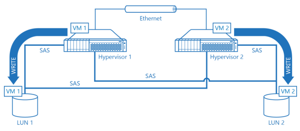
Diagram 5. Hypervisor Cluster with a Dedicated LUN per Hypervisor Node.
On the Diagram 5 there’s a schematic drawing of a hypervisor cluster where every hypervisor node has its own LUN shared over SAS fabric with the other hypervisor node. VM1 runs on node 1 and is stored on LUN 1, which, in turn is owned by node 1. VM2 is configured in a similar fashion: it runs on node 2 which is the primary owner of LUN 2 which storesVM2 is stored. As a result, there’s no resource conflict, no LUN ownership change issues and it is still possible to move VMs between hypervisor nodes for load balancing just losing fraction of the cluster performance because of concurrent ownership or redirected access.
Sample hypervisor cluster on the Diagram 5 can easily survive if any of the hypervisor nodes goes down because the remaining hypervisor node still has full access to the LUN1 so VMs running on failed cluster node will restart on the second cluster node or will continue to work. However, if any of the LUNs connected to both hypervisor nodes becomes unaccessible it would be basically a “game over” since LUNs are not configured to be fault tolerant in the cluster scheme provided above.
Luckily, there’s a nice and elegant way to combine both: mostly exclusive access of a particular hypervisor node to a single LUN for performance, and full fault tolerance as all the components of the hypervisor cluster are duplicated for redundancy.
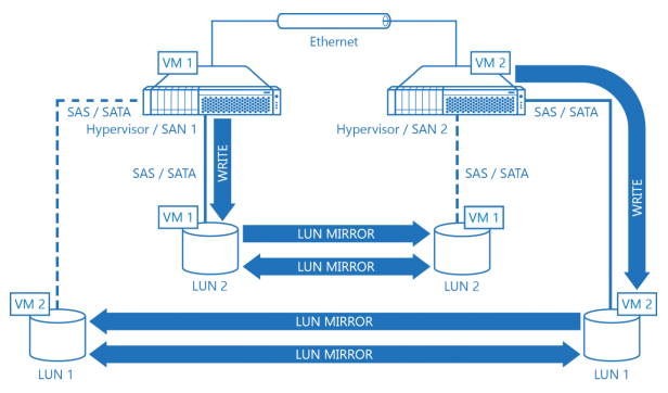
Diagram 6. Fully Redundant Hypervisor Cluster with a Dedicated LUN for Every Node.
Diagram 6 illustrates a hypervisor cluster configured to be fully fault tolerant and deliver maximum performance at the same time. Every combined hypervisor / SAN node has its own dedicated LUN to store VMs so basically, any VM in the cluster virtually runs on DAS. The fault tolerance of every Byte is guaranteed by replication between the partner LUNs, which acts similar to RAID 1 or mirror. All I/O is bound to the local LUN and StarWind Virtual SAN replicates data between the cluster nodes via Ethernet without triggering expensive and time consuming LUN ownership change mechanisms. As writes are confirmed over Ethernet there’s no need to have a SAS infrastructure with all nodes having direct access to all LUNs. Thus, there’s no need to use expensive dual port low capacity SAS since with the proposed design single port high capacity SATA can be used to cut the implementation costs. It’s clearly visible that replication data of each LUN is mostly transferred in a single direction so given scenario also utilizes Ethernet’s full-duplex nature with maximum efficiency. Arrows show how WRITE is performed to LUN 1 and LUN 2, and how it is then mirrored with the partner. Both LUN 1 and LUN 2 are
treated as local by the owner hypervisor node. Dotted lines between LUN 1 and Hypervisor node 2, and LUN 2 and Hypervisor 1 appropriately are logical bonds between virtual SANs and the LUNs used for WRITE confirmation. The hypervisor itself doesn’t touch partner’s LUN. VM1 is running on node 1, stored on local LUN 2 on a persistent basis and replicated to LUN 2 partner attached on node 2. VM2 is running on node 2, stored on local LUN 1 and is replicated to LUN 1 mirror on node 1. This is the default operation mode of the cluster. Should any of the nodes fail, VMs that were running on it are instantly restarted on the partner hypervisor node since all hypervisor nodes have access to one mirror of the LUN and VM data is always up to date.
Scaling Approach
Scaling beyond the 2- and 3-node cluster configurations is not much complex compared to the traditional design. Multi-node hyper-converged hypervisor cluster uses the same building block of a combined hypervisor / SAN node with a set of LUNs replicated between different partner hypervisor nodes.
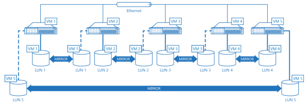
Diagram 7. Five Node Hyper-Converged Hypervisor Cluster with 2-Way HA by StarWind Virtual SAN.
Diagram 7 illustrates a 5-node hypervisor cluster. Cluster is based on a virtual SAN architecture and does 2-way mirroring or duplication so every LUN is replicated to another LUN on a partner node. Every hypervisor node in this example is running a virtual machine which is bounded to a local LUN and also mirrored to a LUN on a partner hypervisor node. Building clusters with 3-way mirroring (triplication) instead of 2-way mirroring is not much different except there are three LUNs attached to every hypervisor node and one LUN is used to store and run virtual machines for the current hypervisor node and other two keep replicas on the partner hypervisor cluster nodes.
Design with a fixed number of replicas is very efficient compared to the so-called wide striping mode where every LUN is striped between the cluster nodes. Same happens to all the virtual machines as their data is also located on all the storage resources controlled by hypervisor cluster. In theory I/O should be multiplied and wide stripped configuration should be faster but in practice there are two issues preventing it from doing this. Issue number one is that local storage is much faster compared to any Ethernet connection. Mostly because of latency as bandwidth is comparable as it was previously mentioned in this document. Second issue is the limited amount of physical network interfaces every hypervisor nodes can have. It does not matter how many partner nodes from a hypervisor cluster can fetch virtual machine data in parallel as all this data has to go through the same bandwidth-limited Ethernet port. Also, with many replicas a thing, opposite to acceleration happens as a lot of time is wasted on synchronization and data processing negotiation with all partner nodes.
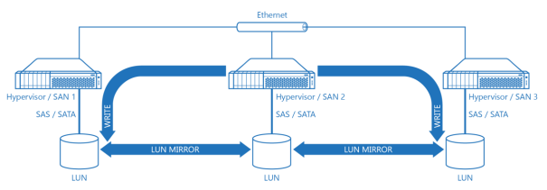
Diagram 8. Three Node Hypervisor Cluster Based on a Virtual SAN Architecture.
On a Diagram 8 there’s a schematic drawing a three node hypervisor cluster based on a virtual SAN architecture. Basically it’s the same picture as Diagram 2a but with arrows showing data movement direction of a WRITE from the Hypervisor / SAN 2 and its Ethernet link. As it is clearly seen, network interface’s bandwidth between particular hypervisor / SAN node and its partners being a bottleneck so increasing amount of nodes capable of feeding or seeding the data does not even theoretically help to reduce time required for I/O operation.
In the recent Windows and Hyper-V versions Microsoft is shifting focus from block to file based protocols for accessing shared virtual machine images over Ethernet. So, SMB 3.0 can eventually replace iSCSI. This has nothing to do with performance as it is obvious that SMB 3.0 needs some block based backend as it has no clustering features directly and this block based backend used without SMB 3.0 wrapping 0 layer will work faster because whole storage stack would provide lower resulting I/O latency. However, Microsoft has no clustered file system and using a combination of a NTFS and SMB where owner node uses NTFS to access data and non-owner is using SMB through owner node in redirected I/O mode is very complex, awkward, and slow. Switching LUN owners is very expensive because NTFS is local file system and never was designed to do fast mount and un-mount and this is very different compared to what VMware VMFS is capable of. Also, Microsoft has no hardware acceleration features like ODX to offload LUN-specific commands to the hardware and this is again very different to VMware and its VAAI with ATS. Accessing shared virtual machine images over SMB 3.0 is very similar to what VMware is doing with NFS as it is file server who’s granting access from a hypervisor node to a virtual machine image on a per-file basis rather then it’s an iSCSI target doing the same for a group of a virtual machine images stored on an iSCSI LUN. File based protocols are easier to manage for a user and also keeping files instead of whole LUN images does better job in terms of thin provisioning. Unallocated space with virtual machine image is never wasted when only virtual machine images are stored on a file system and not on intermediate pre-allocated LUNs which are usually thick provisioned because of the performance reasons. With SMB 3.0 being a core protocol to power so-called Scale-Out File Server will result in network topology becoming similar to the traditional SAN design drawn on a Diagram 1 except SAN nodes would be replaced with a SoFS nodes using some block based back end which could be Fibre Channel, SAS or iSCSI. So iSCSI is where StarWind is coming to play. StarWind Software is not intended to argue against Microsoft activities and trends but offers customers both ways to go and freedom of choice. Customer can use virtual SAN with a hardware minimalistic and maximum performance approach. If customer has a reason to stick with a Scale-Out File Server design StarWind can provide a hardware-less way to cluster multiple Scale-Out File Servers and use virtual SAN as a shared storage backend for SMB 3.0 being used to keep virtual machine images on. Hardware footprint of the resulting solution would be still as big as with a traditional SAN approach. Performance would be a compromise since I/O would be unbound for every particular node, and always touching Ethernet, and not doing most of the reads locally and doing writes with a minimum amount of redirection and processing. The only thing StarWind would be able to do is to cut down implementation cost making it possible to use cheap high capacity SATA disks with combined SAN / SoFS cluster nodes and no physical shared storage hardware.
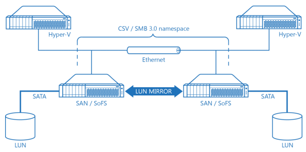
Diagram 9. Hyper-V Cluster with a Scale-Out File Server Cluster Using Virtual SAN Shared Storage.
On a Diagram 9 there’s a schematic drawing of a Hyper-V cluster using Scale-Out File Server as a shared storage to keep virtual machine images on. Combined SAN / SoFS nodes don’t have any physical shared storage hardware for a Clustered Shared Volume as they are using StarWind virtual SAN which basically mirrors SATA spindles attached to every SAN / SoFS node to each other, creating high performance fault tolerant LUN for CSV. Resulting configuration has the lowest implementation cost because of the absolute minimum of utilized hardware and also because of the ability to use cheap SATA and not expensive SAS storage. Also, it’s also quite well performing because of all the already referenced performance benefits virtual SAN has, compared to any hardware SAN design.
