

StarWind Virtual SAN: Configuration Guide for Microsoft Windows Server [Hyper-V], VSAN Deployed as a Controller VM using GUI
- April 24, 2023
- 43 min read
- Download as PDF
Annotation
Relevant products
This guide applies to StarWind Virtual SAN and StarWind Virtual SAN Free (OVF Version 20230901 Version V8 (build 15260) or earlier.)
For newer versions of StarWind Virtual SAN (CVM Version 20231016 and later), please refer to this configuration guide:
StarWind Virtual SAN: Configuration Guide for Microsoft Windows Server [Hyper-V], VSAN Deployed as a Controller Virtual Machine (CVM) using Web UI – Resource Library
Purpose
This document outlines how to configure a Microsoft Hyper-V Failover Cluster using StarWind Virtual SAN (VSAN), with VSAN running as a Controller Virtual Machine (CVM). The guide includes steps to prepare Hyper-V hosts for clustering, configure physical and virtual networking, and set up the Virtual SAN Controller Virtual Machine.
For more information about StarWind VSAN architecture and available installation options, please refer to the StarWind Virtual (VSAN) Getting Started Guide.
Audience
This technical guide is intended for storage and virtualization architects, system administrators, and partners designing virtualized environments using StarWind Virtual SAN (VSAN).
Expected result
The end result of following this guide will be a fully configured high-availability Windows Failover Cluster that includes virtual machine shared storage provided by StarWind VSAN.
NOTICE: This guide universally applies to both 2-node and 3-node clusters. Please follow the quick notes within the configuration steps to carry out the necessary actions required for each cluster size.
Prerequisites
StarWind Virtual SAN system requirements
Prior to installing StarWind Virtual SAN, please make sure that the system meets the requirements, which are available via the following link:
https://www.starwindsoftware.com/system-requirements
Recommended RAID settings for HDD and SSD disks:
https://knowledgebase.starwindsoftware.com/guidance/recommended-raid-settings-for-hdd-and-ssd-disks/
Please read StarWind Virtual SAN Best Practices document for additional information:
https://www.starwindsoftware.com/resource-library/starwind-virtual-san-best-practices
Solution diagram
The diagrams below illustrate the network and storage configuration of the solution:
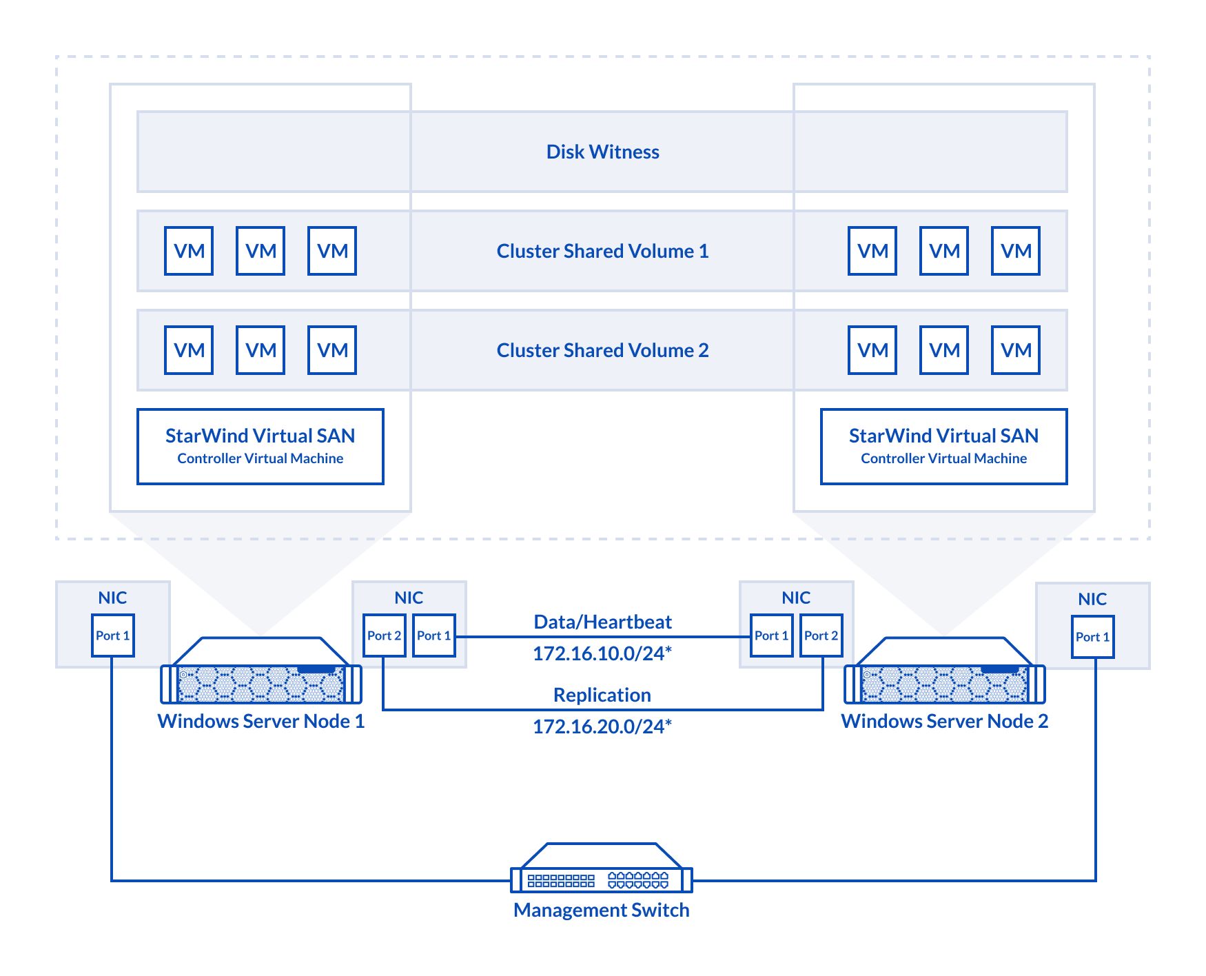 2-node cluster
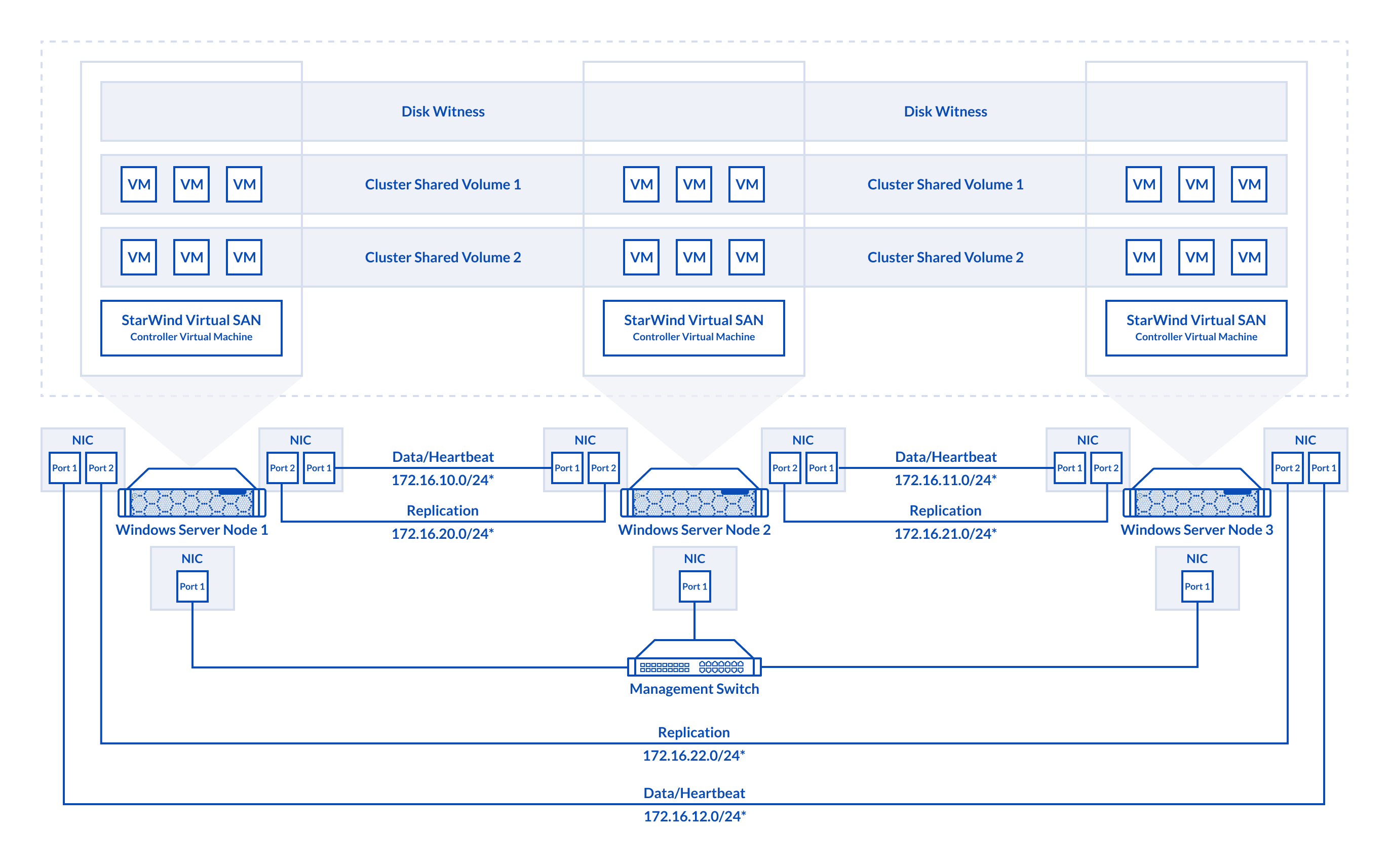
3-node cluster
Preconfiguring cluster nodes
1. Make sure that a domain controller is configured and the servers are added to the domain.
NOTE: Please follow the recommendation in KB article on how to place a DC in case of StarWind Virtual SAN usage.
2. Deploy Windows Server on each server and install Failover Clustering and Multipath I/O features, as well as the Hyper-V role on both servers. This can be done through Server Manager (Add Roles and Features menu item).
3. Define at least 2x network interfaces (2 node scenario) or 4x network interfaces (3 node scenario) on each node that will be used for the Synchronization and iSCSI/StarWind heartbeat traffic. Do not use iSCSI/Heartbeat and Synchronization channels over the same physical link. Synchronization and iSCSI/Heartbeat links can be connected either via redundant switches or directly between the nodes (see diagram above).
4. Separate external Virtual Switches should be created for iSCSI and Synchronization traffic based on the selected before iSCSI and Synchronization interfaces. Using Hyper-V Manager open Virtual Switch Manager and create two external Virtual Switches: one for the iSCSI/StarWind Heartbeat channel (iSCSI) and another one for the Synchronization channel (Sync).
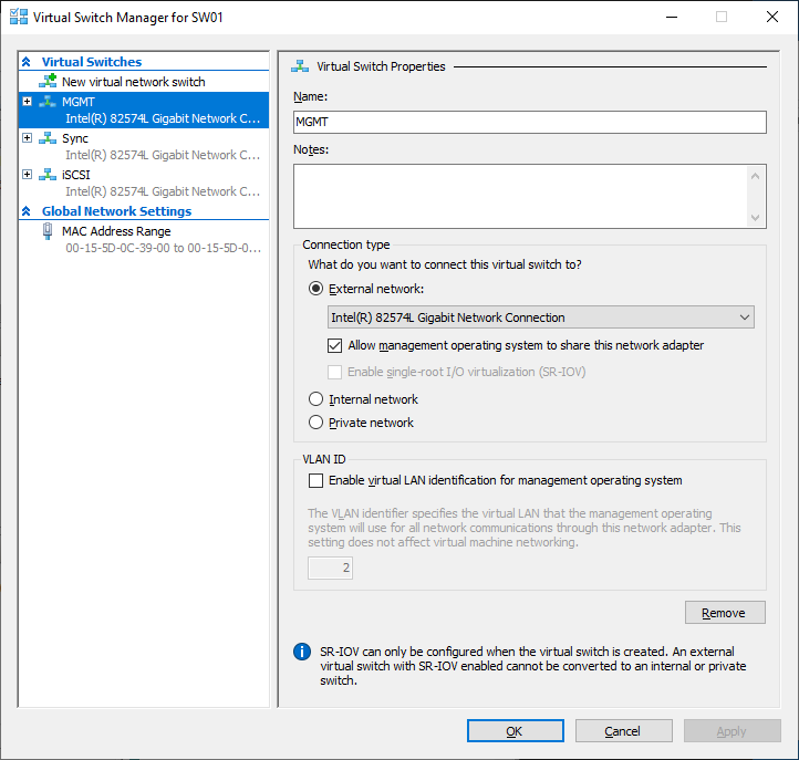
5. Configure and set the IP address on each virtual switch interface. In this document, 172.16.1x.x subnets are used for iSCSI/StarWind heartbeat traffic, while 172.16.2x.x subnets are used for the Synchronization traffic.
NOTE: In case NIC supports SR-IOV, enable it for the best performance. An additional internal switch is required for iSCSI Connection. Contact support for additional details.
6. Set MTU size to 9000 on iSCSI and Sync interfaces using the following Powershell script.
$iSCSIs = (Get-NetAdapter -Name "*iSCSI*").Name
$Syncs = (Get-NetAdapter -Name "*Sync*").Name
foreach ($iSCSI in $iSCSIs) {
Set-NetAdapterAdvancedProperty -Name “$iSCSI” -RegistryKeyword “*JumboPacket” -Registryvalue 9014
Get-NetAdapterAdvancedProperty -Name "$iSCSI" -RegistryKeyword “*JumboPacket”
}
foreach ($Sync in $Syncs) {
Set-NetAdapterAdvancedProperty -Name “$Sync” -RegistryKeyword “*JumboPacket” -Registryvalue 9014
Get-NetAdapterAdvancedProperty -Name "$Sync" -RegistryKeyword “*JumboPacket”
}
It will apply MTU 9000 to all iSCSI and Sync interfaces if they have iSCSI or Sync as part of their name.
NOTE: MTU setting should be applied on the adapters only if there is no live production running through the NICs.
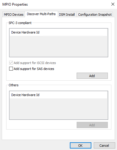
7. Open the MPIO Properties manager: Start -> Windows Administrative Tools -> MPIO. Alternatively, run the following PowerShell command :
mpiocpl
8. In the Discover Multi-Paths tab, select the Add support for iSCSI devices checkbox and click Add.
9. When prompted to restart the server, click Yes to proceed.
10. Repeat the same procedure on the other server.
Installing File Server Roles
Please follow the steps below if file shares configuration is required
Scale-Out File Server (SOFS) for application data
1. Open Server Manager: Start -> Server Manager.
2. Select: Manage -> Add Roles and Features.
3. Follow the installation wizard steps to install the roles selected in the screenshot below:
4. Restart the server after installation is completed and perform steps above on the each server.
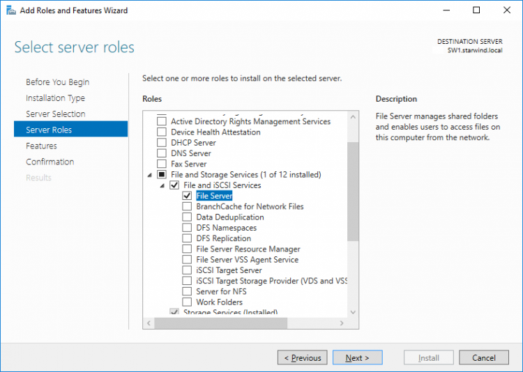
File Server for general use with SMB share
1. Open Server Manager: Start -> Server Manager.
2. Select: Manage -> Add Roles and Features.
3. Follow the installation wizard steps to install the roles selected in the screenshot below:
4. Restart the server after installation is completed and perform steps above on each server.
File Server for general use with NFS share
1. Open Server Manager: Start -> Server Manager.
2. Select: Manage -> Add Roles and Features.
3. Follow the installation wizard steps to install the roles selected in the screenshot below:
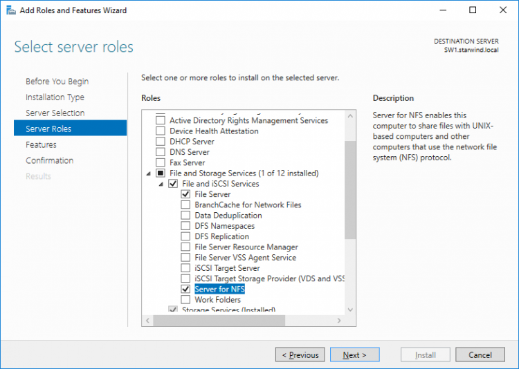
4. Restart the server after installation is completed and perform steps above on each server.
Deploying StarWind Virtual SAN CVM
1. Download StarWind VSAN CVM to the Hyper-V server:
VSAN by StarWind: Overview
2. Extract the VM .vhdx file from the downloaded archive.
3. Open Hyper-V Manager and create a new Hyper-V VM.
4. Specify the name of the virtual machine with StarWind VSAN, and choose the location for the VM. For example: C:\SW1\
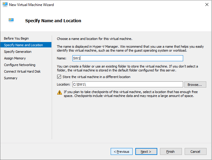
5. Copy .vhdx to the folder where the VM was created. In this case, its C:\ SW1\Virtual Hard Disks\
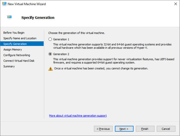
6. Choose Generation 2 VM.
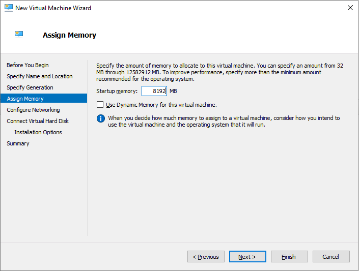
7. Assign memory to the VM. We recommend allocating at least 8GB of RAM for StarWind CVM. If StarWind L1 cache is used, an appropriate amount of RAM should be assigned.
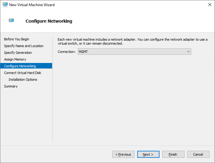
8. Choose the management network for the VM.
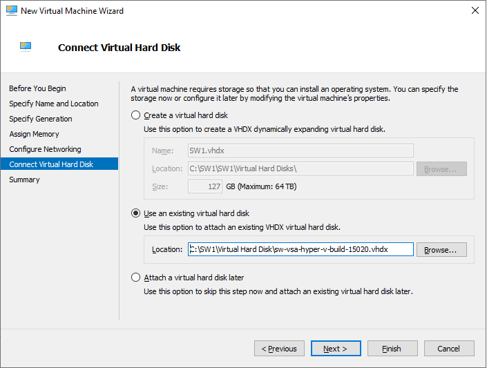
9. Connect .vhdx to the VM.
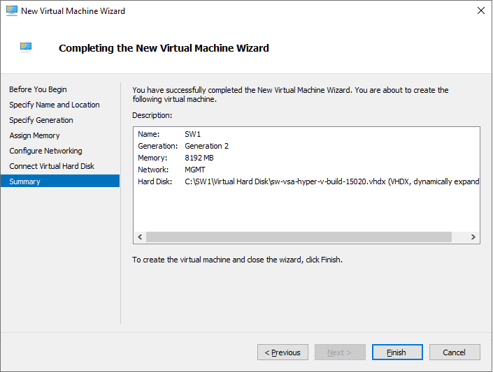
10. Review the Summary and click Finish to create the VM.
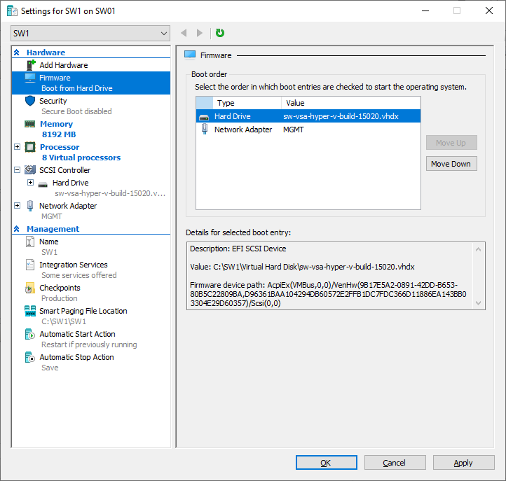
11. Right-click on the VM and choose Settings. Open Firmware and move the option Hard Drive to the first place in the list.
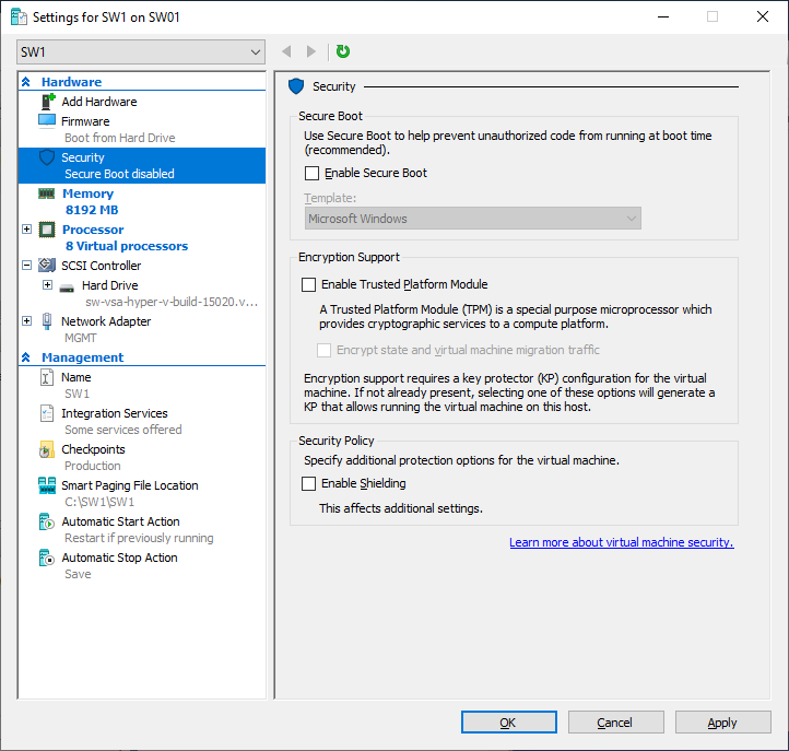
12. Go to the Security page and uncheck the Enable Secure Boot box.
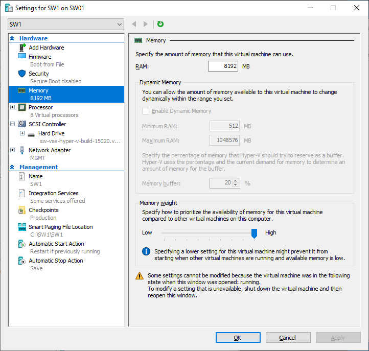
13. Go to Memory and move the slider for Memory weight to High.
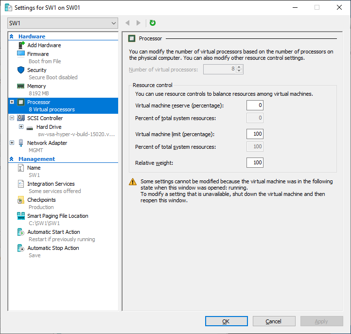
14. Go to Processor and assign 8 vCPUs to the VM.
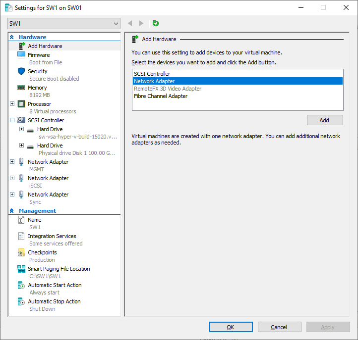
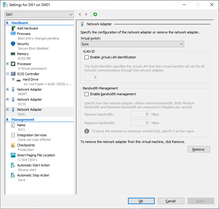
15. Click Add Hardware and add NICs for iSCSI and Synchronization traffic to the VM.
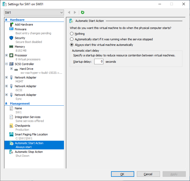
16. Configure Automatic Start and Stop actions, so the VM will always start automatically.
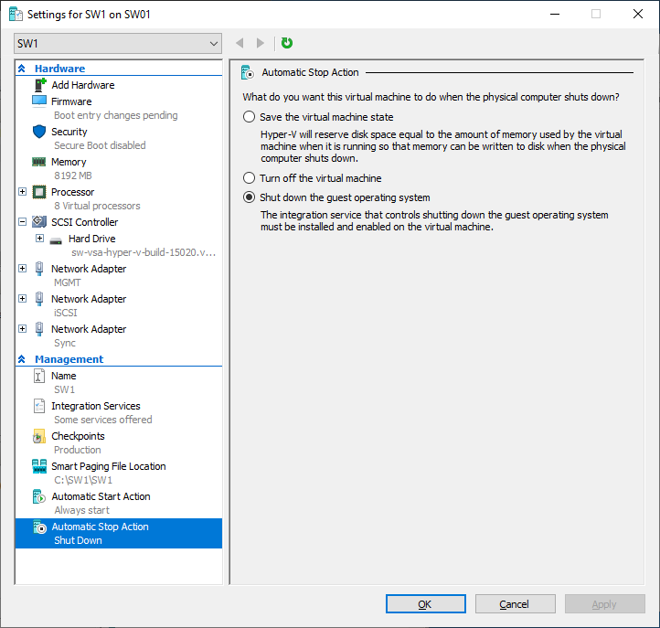
17. Choose Shut down the guest operating system as an Automatic Stop Action.
18. Repeat all the steps from this section on other Windows Server hosts.
19. Start virtual machines on all Windows Server hosts.
Configuring StarWind Virtual SAN VM settings
1. Open the VM console and check the IP address received via DHCP (or which was assigned manually).
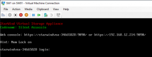
Another alternative is to log into the VM via console and assign static IP using nmcli if there is no DHCP,
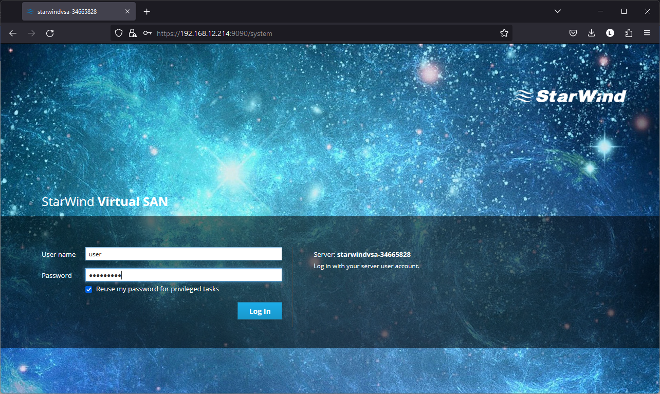
2. Now, open the web browser and enter the IP address of the VM. Log into the VM using the following default credentials:
- username: user
- password: rds123RDS
- NOTE: Make sure to check the “Reuse my password for privileged tasks” box
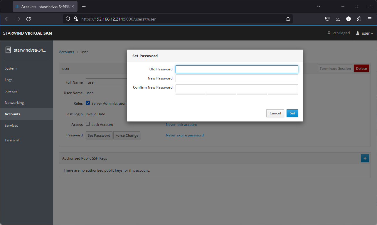
3. After a successful login, click Accounts on the left sidebar.
4. Select a user and click Set Password.
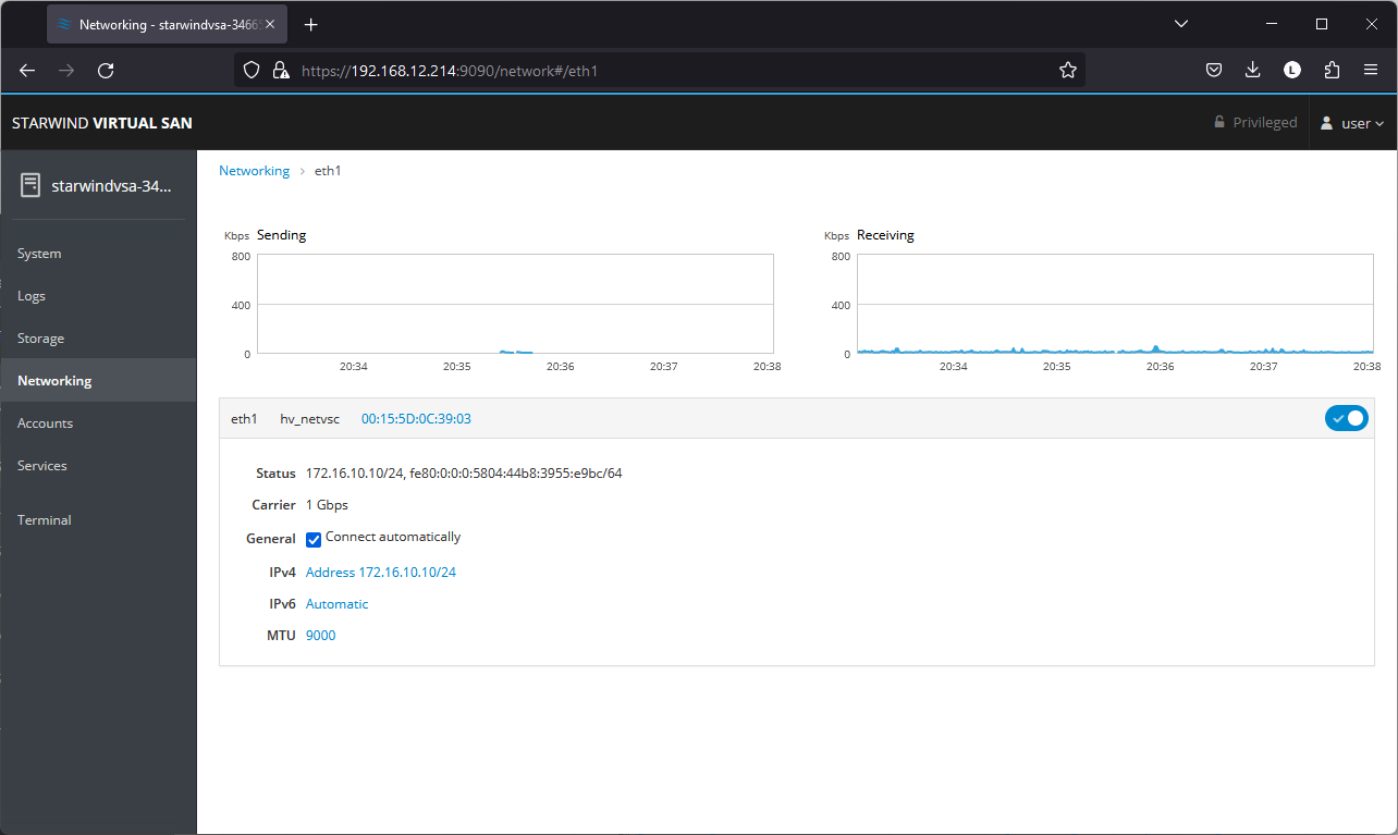
5. On the left sidebar, click Networking.
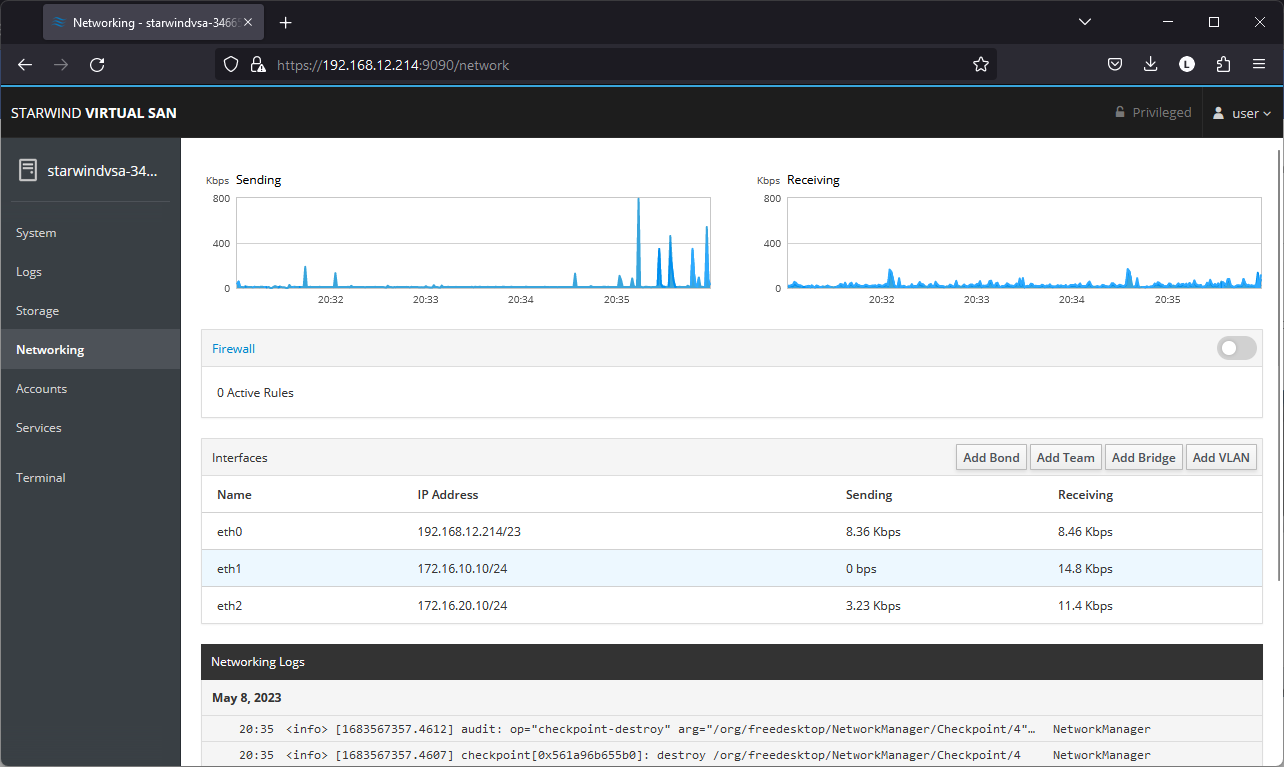
Here, the Management IP address of the StarWind Virtual SAN Virtual Machine can be configured, as well as IP addresses for iSCSI and Synchronization networks. In case the Network interface is inactive, click on the interface, turn it on, and set it to Connect automatically.
6. Click on Automatic (DHCP) to set the IP address (DNS and gateway – for Management).
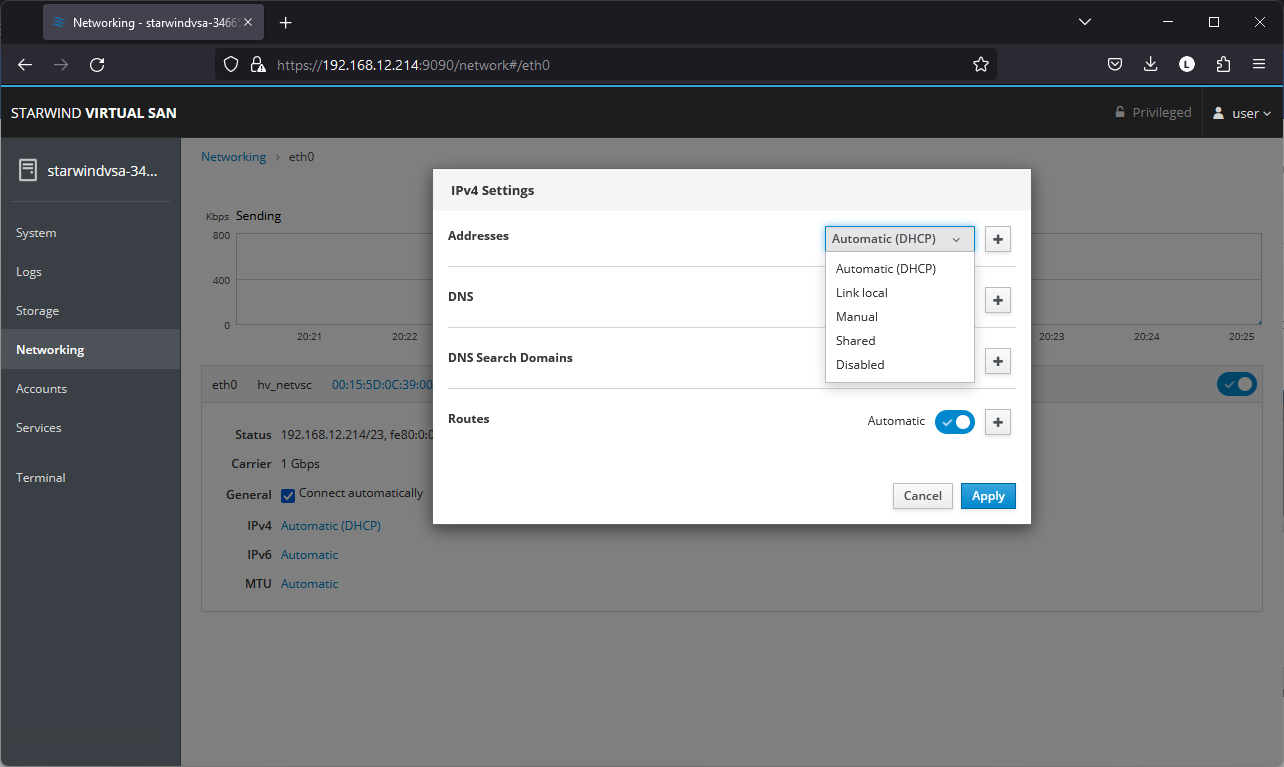
7. The result should look like in the picture below:
NOTE: It is recommended to set MTU to 9000 on interfaces dedicated for iSCSI and Synchronization traffic. Change Automatic to 9000, if required.
8. Alternatively, log into the VM via the VMware console and assign a static IP address by editing the configuration file of the interface located by the following path: /etc/sysconfig/network-scripts
9.Open the file corresponding to the Management interface using a text editor, for example: sudo nano /etc/sysconfig/network-scripts/ifcfg-eth0
10. Edit the file:
- change the line BOOTPROTO=dhcp to: BOOTPROTO=static
- add the IP settings needed to the file:
- IPADDR=192.168.12.10
- NETMASK=255.255.255.0
- GATEWAY=192.168.12.1
- DNS1=192.168.1.1
11. Restart the interface using the following cmdlet: sudo ifdown eth0, sudo ifup eth0, or restart the VM.
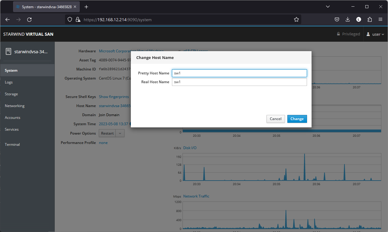
12. Change the Host Name from the System tab by clicking on it:
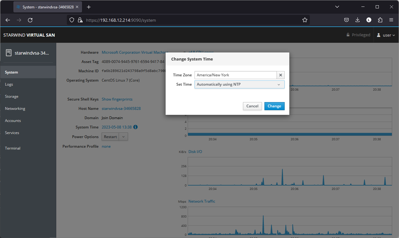
13. Change System time and NTP settings if required:
14. Repeat the steps above on each StarWind VSAN VM.
Configuring Storage
StarWind Virtual SAN for vSphere can work on top of Hardware RAID or Linux Software RAID (MDADM) inside of the Virtual Machine.
Please select the required option:
Configuring storage with hardware RAID
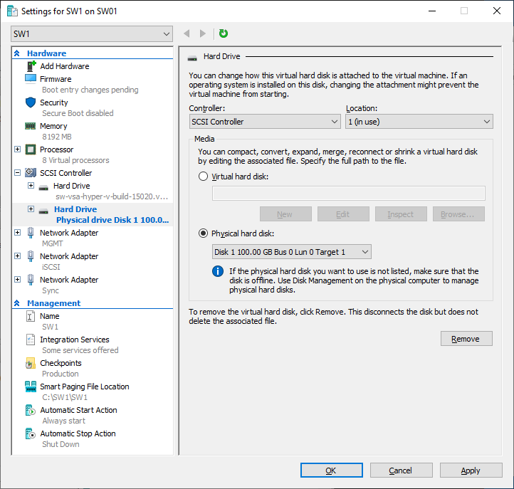
1. Open VM Settings in Hyper-V and add drive to the VM, which going to be used by StarWind service. It is recommended to pass the entire RAID array to the VM by selecting a physical hard disk option.
NOTE: Using virtual hard disks is not recommended due to potential performance issues. Thick provisioned virtual disks should be used to improve storage performance.
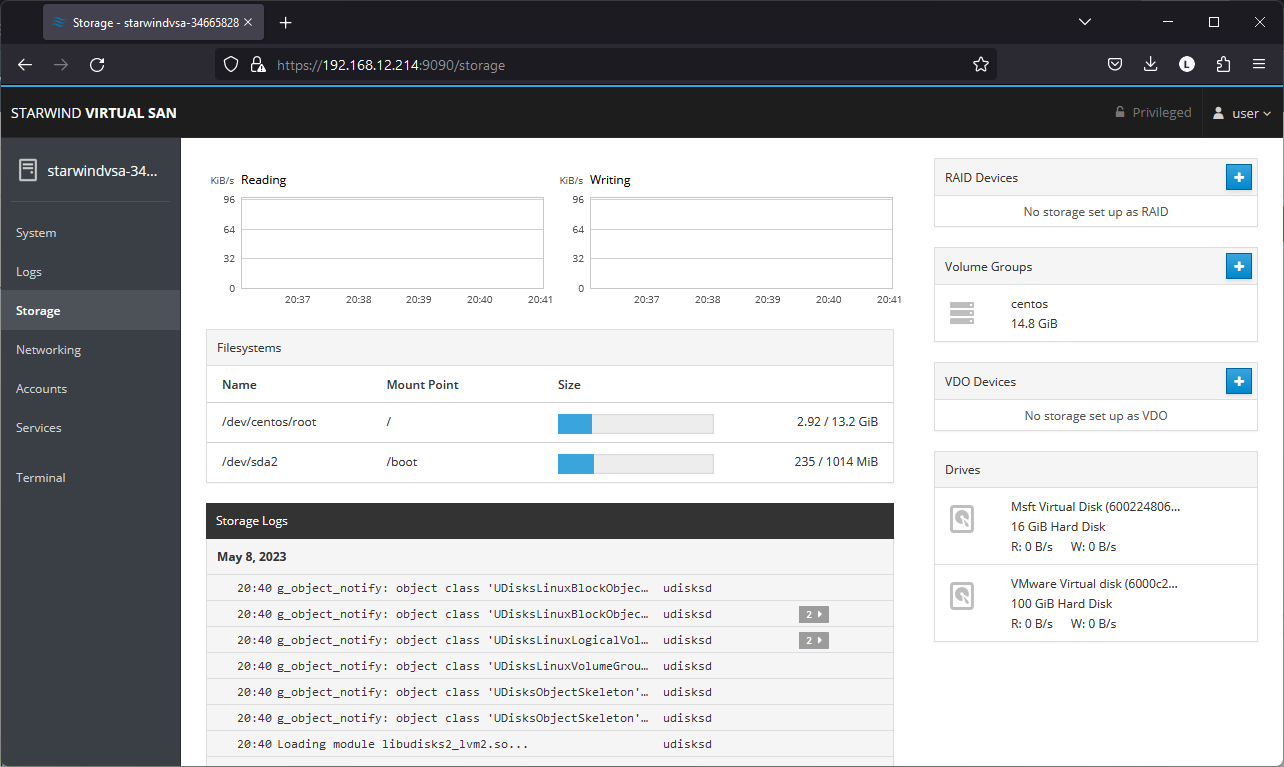
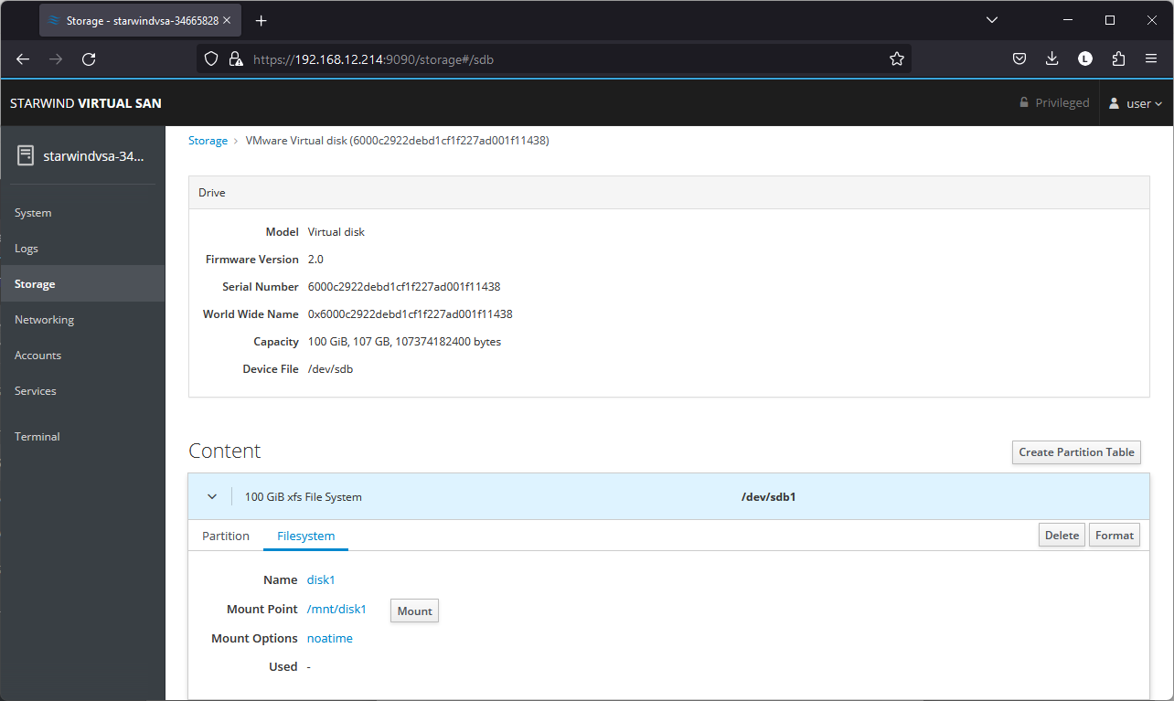
2. Login to StarWind VSAN VM web console and access the Storage section. Locate the recently added disk in the Drives section and choose it.
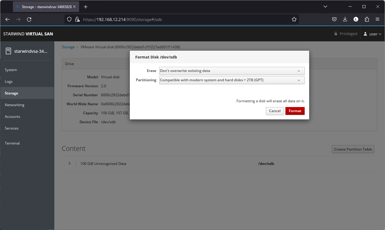
3. The added disk does not have any partitions and filesystem. Press the Create Partition Table button to create the partition.
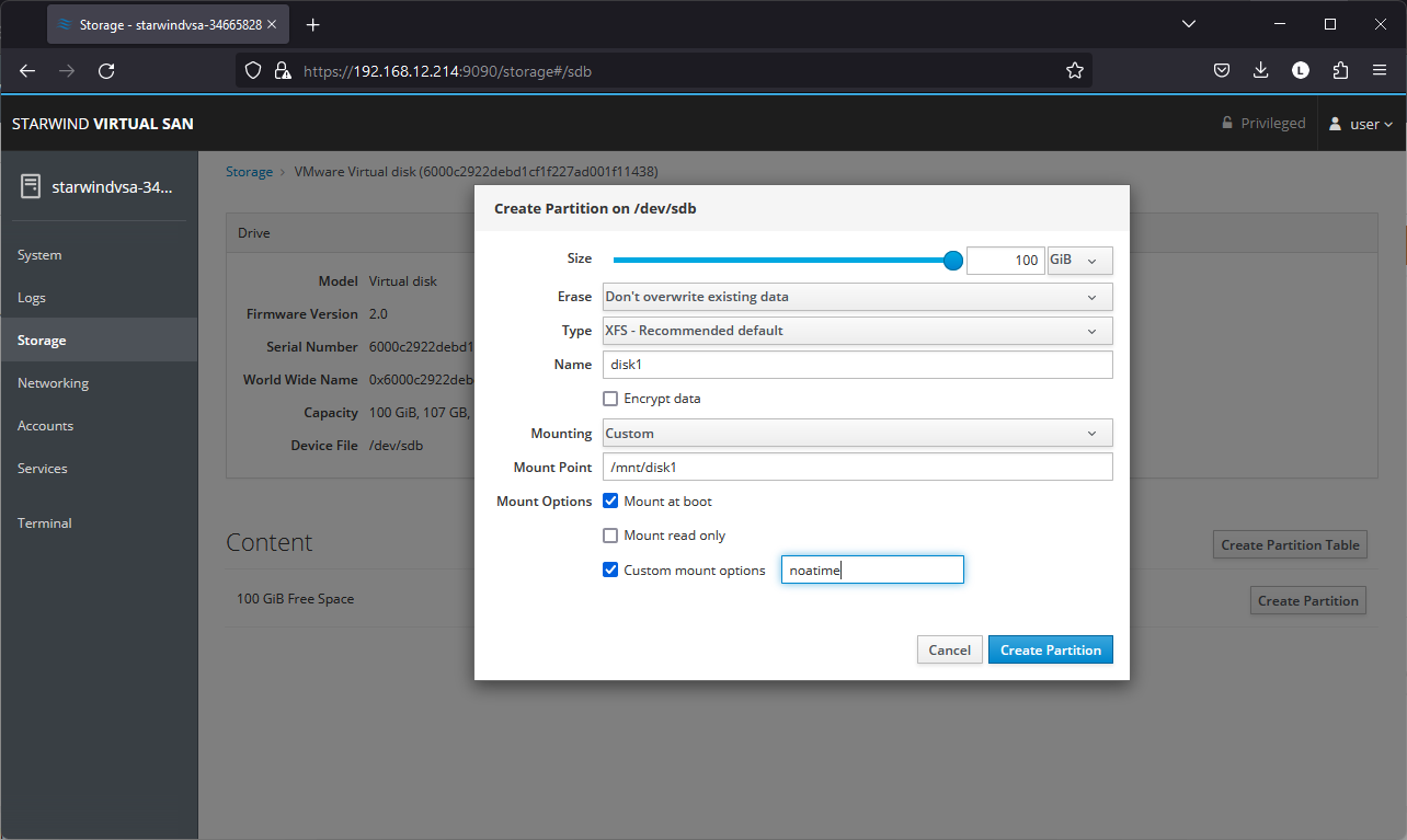
4. Press Create Partition to format the disk and set the mount point. The mount point should be as follows: /mnt/%yourdiskname%
5. On the Storage section, under Content, navigate to the Filesystem tab. Click Mount.
Configuring StarWind Management Console
1. Install StarWind Management Console on each server or on a separate workstation with Windows OS (Windows 7 or higher, Windows Server 2008 R2 and higher) using the installer available here.
NOTE: StarWind Management Console and PowerShell Management Library components are required.
2. Select the appropriate option to apply the StarWind License key.
Once the appropriate license key has been received, it should be applied to StarWind Virtual SAN service via Management Console or PowerShell.
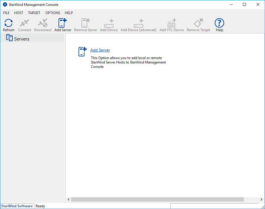
3. Open StarWind Management Console and click Add Server.
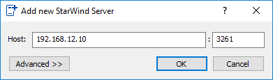
4. Type the IP address of the StarWind Virtual SAN in the pop-up window and click OK.
5. Select the server and click Connect.
6. Click Apply Key… on the pop-up window.

7. Select Load license from file and click the Load button.
8. Select the appropriate license key.
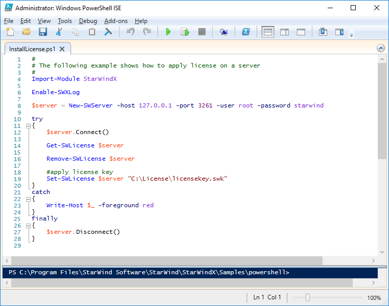
As an alternative, PowerShell can be used. Open StarWind InstallLicense.ps1 script with PowerShell ISE as administrator. It can be found here:
C:\Program Files\StarWind Software\StarWind\StarWindX\Samples\powershell\InstallLicense.ps1
Type the IP address of StarWind Virtual SAN VM and credentials of StarWind Virtual SAN service (defaults login: root, password: starwind).
Add the path to the license key.
9. After the license key is applied, StarWind devices can be created.
NOTE: In order to manage StarWind Virtual SAN service (e.g. create ImageFile devices, VTL devices, etc.), StarWind Management Console can be used.
Creating StarWind devices
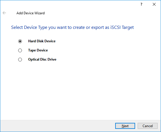
1. In the StarWind Management Console click to Add Device (advanced) button and open Add Device (advanced) Wizard.
2. Select Hard Disk Device as the type of device to be created.
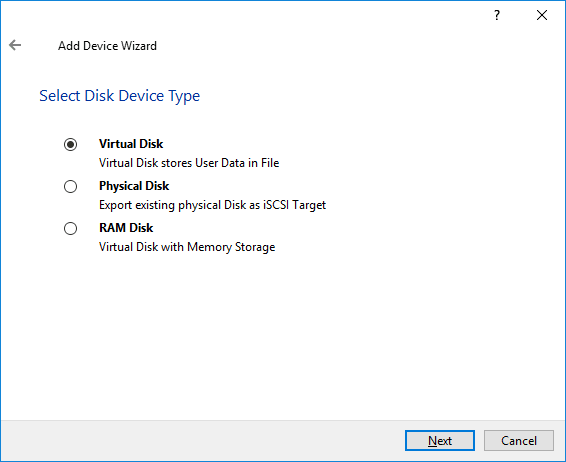
3. Select Virtual Disk.
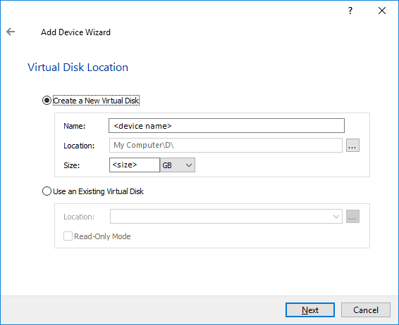
4. Specify a virtual disk Name, Location, and Size.
5. Select the Thick provisioned disk type and block size.
NOTE: Use 4096 sector size for targets, connected on Windows-based systems and 512 bytes sector size for targets, connected on Linux-based systems (ESXi/Xen/KVM).
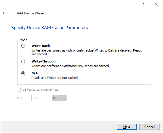
6. Define a caching policy and specify a cache size (in MB). Also, the maximum available cache size can be specified by selecting the appropriate checkbox. Optionally, define the L2 caching policy and cache size.
7. Specify Target Parameters. Select the Target Name checkbox to enter a custom target name. Otherwise, the name is generated automatically in accordance with the specified target alias.
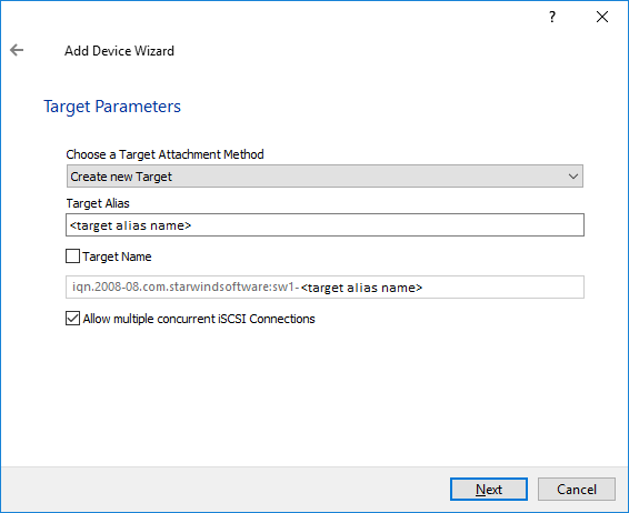
8. Click Create to add a new device and attach it to the target.
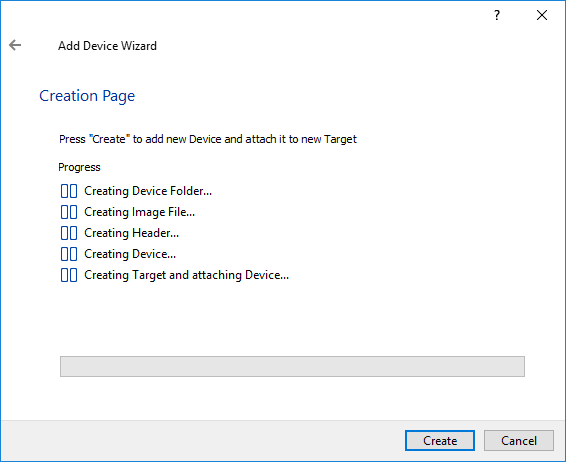
9. Click Close to finish the device creation.
10. The successfully added devices appear in the StarWind Management Console.
Select the Required Replication Mode
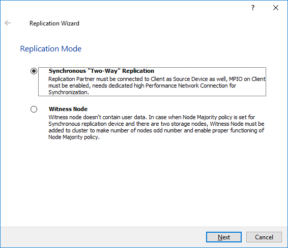
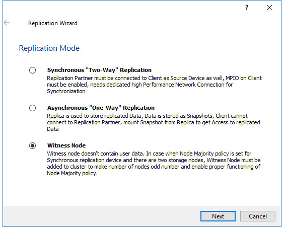
The replication can be configured using Synchronous “Two-Way” Replication mode:
Synchronous or active-active replication ensures real-time synchronization and load balancing of data between two or three cluster nodes. Such a configuration tolerates the failure of two out of three storage nodes and enables the creation of an effective business continuity plan. With synchronous mirroring, each write operation requires control confirmation from both storage nodes. It guarantees the reliability of data transfers but is demanding in bandwidth since mirroring will not work on high-latency networks.
Synchronous “Two-Way” replication
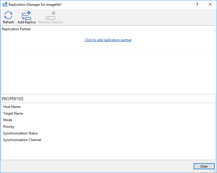
1. Right-click the recently created device and select Replication Manager from the shortcut menu.
2. Select the Add Replica button in the top menu.
3. Select Synchronous “Two-Way” replication as a replication mode.
4. Specify a partner Host name or IP address and Port Number.
Selecting the Failover Strategy
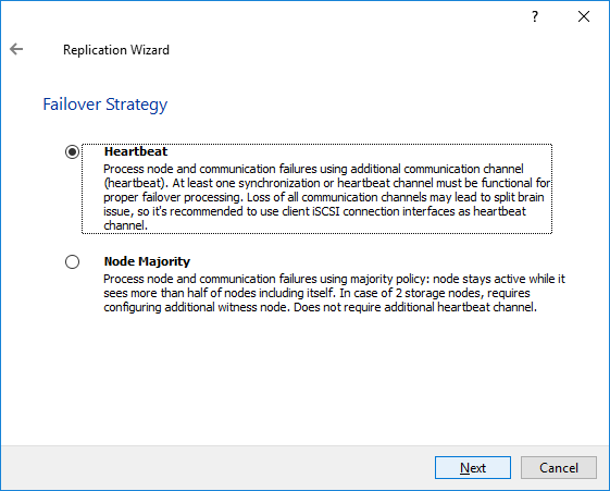
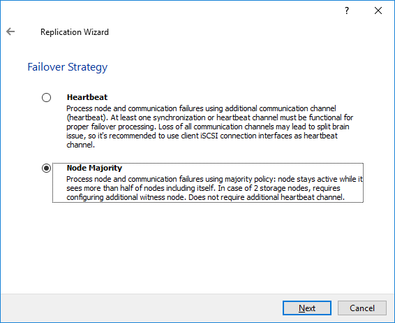
StarWind provides 2 options for configuring a failover strategy:
Heartbeat
The Heartbeat failover strategy allows avoiding the “split-brain” scenario when the HA cluster nodes are unable to synchronize but continue to accept write commands from the initiators independently. It can occur when all synchronization and heartbeat channels disconnect simultaneously, and the partner nodes do not respond to the node’s requests. As a result, StarWind service assumes the partner nodes to be offline and continues operations on a single-node mode using data written to it.
If at least one heartbeat link is online, StarWind services can communicate with each other via this link. The device with the lowest priority will be marked as not synchronized and get subsequently blocked for the further read and write operations until the synchronization channel resumption. At the same time, the partner device on the synchronized node flushes data from the cache to the disk to preserve data integrity in case the node goes down unexpectedly. It is recommended to assign more independent heartbeat channels during the replica creation to improve system stability and avoid the “split-brain” issue.
With the heartbeat failover strategy, the storage cluster will continue working with only one StarWind node available.
Node Majority
The Node Majority failover strategy ensures the synchronization connection without any additional heartbeat links. The failure-handling process occurs when the node has detected the absence of the connection with the partner.
The main requirement for keeping the node operational is an active connection with more than half of the HA device’s nodes. Calculation of the available partners is based on their “votes”.
In case of a two-node HA storage, all nodes will be disconnected if there is a problem on the node itself, or in communication between them. Therefore, the Node Majority failover strategy requires the addition of the third Witness node or file share (SMB) which participates in the nodes count for the majority, but neither contains data on it nor is involved in processing clients’ requests. In case an HA device is replicated between 3 nodes, no Witness node is required.
With Node Majority failover strategy, failure of only one node can be tolerated. If two nodes fail, the third node will also become unavailable to clients’ requests.
Please select the required option:
Heartbeat
1. Select Failover Strategy.
2. Select Create new Partner Device and click Next.
3. Select a partner device Location and click Next.
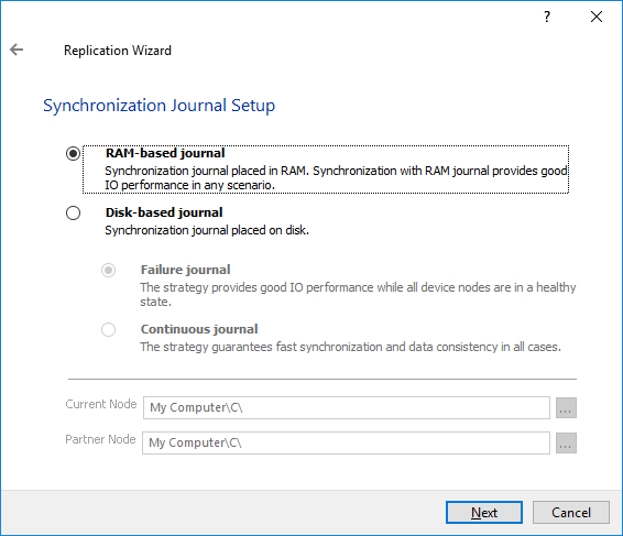
4. Select Synchronization Journal Strategy and click Next.
NOTE: There are several options – RAM-based journal (default) and Disk-based journal with failure and continuous strategy, that allow to avoid full synchronization cases.
RAM-based (default) synchronization journal is placed in RAM. Synchronization with RAM journal provides good I/O performance in any scenario. Full synchronization could occur in the cases described in this KB: https://knowledgebase.starwindsoftware.com/explanation/reasons-why-full-synchronization-may-start/
Disk-based journal placed on a separate disk from StarWind devices. It allows to avoid full synchronization for the devices where it’s configured even when StarWind service is being stopped on all nodes.
Disk-based synchronization journal should be placed on a separate, preferably faster disk from StarWind devices. SSDs and NVMe disks are recommended as the device performance is defined by the disk speed, where the journal is located. For example, it can be placed on the OS boot volume.
It is required to allocate 2 MB of disk space for the synchronization journal per 1 TB of HA device size with a disk-based journal configured and 2-way replication and 4MB per 1 TB of HA device size for 3-way replication.
Failure journal – provides good I/O performance, as a RAM-based journal, while all device nodes are in a healthy synchronized state. If a device on one node went into a not synchronized state, the disk-based journal activates and a performance drop could occur as the device performance is defined by the disk speed, where the journal is located. Fast synchronization is not guaranteed in all cases. For example, if a simultaneous hard reset of all nodes occurs, full synchronization will occur.
Continuous journal – guarantees fast synchronization and data consistency in all cases. Although, this strategy has the worst I/O performance, because of frequent write operations to the journal, located on the disk, where the journal is located.
5. Click Change Network Settings.
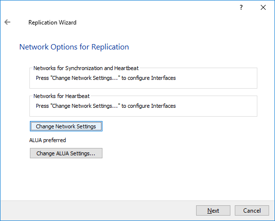
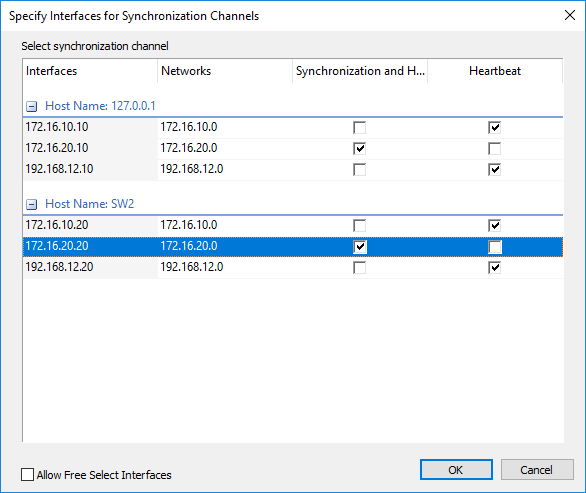
6. Specify the interfaces for Synchronization and Heartbeat Channels. Click OK and then click Next.
7. In Select Partner Device Initialization Mode, select Synchronize from existing Device and click Next.
8. Click Create Replica. Click Finish to close the wizard.
The successfully added device appears in StarWind Management Console.
9. Follow the same procedure for the creation of other virtual disks that will be used as storage repositories.
Node Majority
There are two ways to configure Witness for 2-nodes StarWind HA device, created with Node Majority Failover Strategy: File Share (SMB) as Witness and additional server as Witness Node.
– Creating HA device with File SHare(SMB) as Witness:
SMB Witness is a file, located on SMB share, which can be accessed by both nodes and help them to eliminate the split-brain issue in case of synchronization connection interruption between the nodes. To set up the SMB file share as a Witness for 2-nodes HA device with Node Majority Failover Strategy, perform the actions, described on this page:
https://www.starwindsoftware.com/help/ConfiguringFileShareSMBasWitness.html
– Creating HA device with Witness Node:
1. Select the Node Majority failover strategy and click Next.
2. Choose Create new Partner Device and click Next.
3. Specify the partner device Location and modify the target name if necessary. Click Next. Select Synchronization Journal strategy and location and click Next.
4. In Network Options for Replication, press the Change network settings button and select the synchronization channel for the HA device.
5. In Specify Interfaces for Synchronization Channels, select the checkboxes with the appropriate networks and click OK. Then click Next.
6. Select Synchronize from existing Device as the partner device initialization mode.
7. Press the Create Replica button and close the wizard.
8. The added devices will appear in StarWind Management Console.
Repeat the steps above to create other virtual disks if necessary.
Adding Witness Node
Witness node can be configured on a separate host or as a virtual machine in a cloud. It requires StarWind Virtual SAN service installed on it.
NOTE: Since the device created in this guide is replicated between 2 active nodes with the Node Majority failover strategy, a Witness node must be added to it.
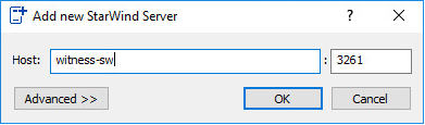
1. Open StarWind Management Console, right-click on the Servers field and press the Add Server button. Add a new StarWind Server which will be used as the Witness node and click OK.
2. Right-click on the HA device with the configured Node Majority failover policy and select Replication Manager and press the Add Replica button.
3. Select Witness Node.
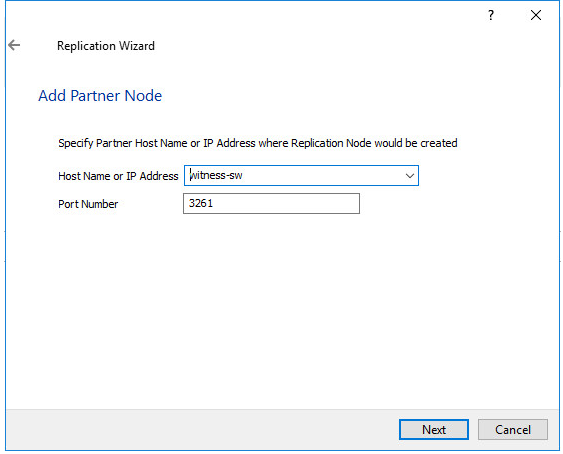
4. Specify the Witness node Host Name or IP address. The default Port Number is 3261.
5. In Partner Device Setup, specify the Witness device Location. Optionally, modify the target name by clicking the appropriate button.
6. In Network Options for Replication, select the synchronization channel with the Witness node by clicking the Change Network Settings button.
7. Specify the interface for Synchronization and Heartbeat and click OK.
8. Click Create Replica and then close the wizard.
9. Repeat the steps above to create other virtual disks if necessary.
NOTE: To extend an Image File or a StarWind HA device to the required size, please check the article below:
2-Node: Provisioning StarWind HA Storage to Windows Server Hosts
Discovery of StarWind iSCSI targets on Windows Server hosts
1. Open Start/Search and type “iSCSI Initiator” to Launch Microsoft iSCSI Initiator. Alternatively, start Command Prompt (CMD) and execute the following command:
iscsicpl
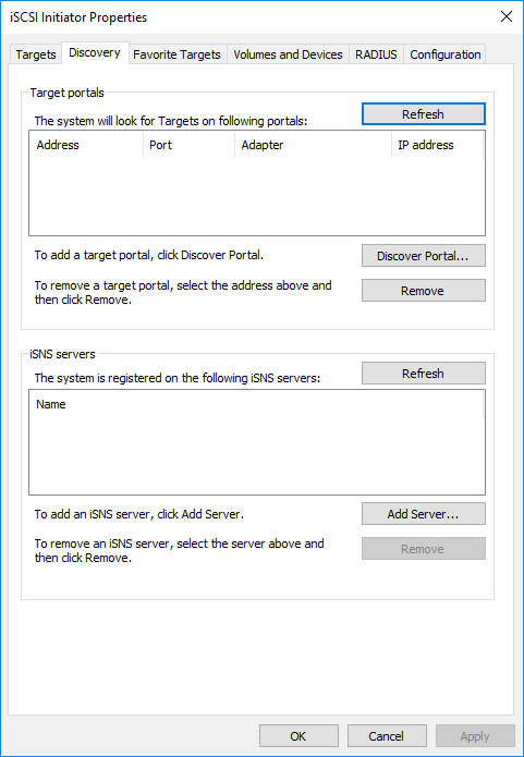
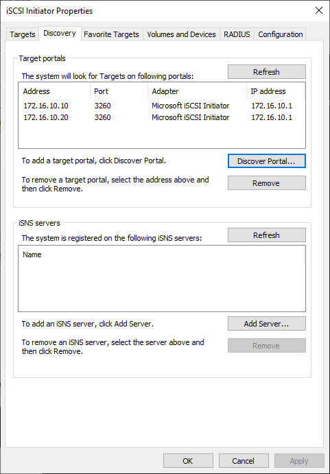
2. In the iSCSI Initiator Properties window, navigate to the Discovery tab and click Discover Portal…
3. In the Discover Target Portal window, enter the IP address of the first StarWind Appliance’s Data network interface (for example, appliance “SW1” with the IP address 172.16.10.10), then click Advanced…
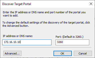
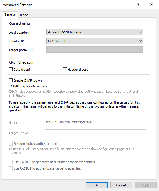
4. In the Advanced Settings window, under the Connect using section, select Microsoft iSCSI Initiator as the Local adapter. Then, select the IP address of the Data/Heartbeat network of the current Windows Server host as the Initiator IP, and click Apply.
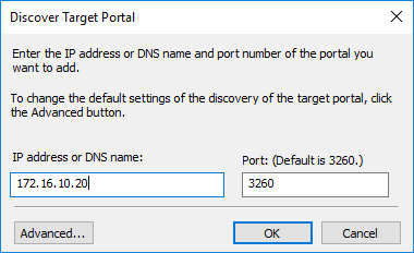
5. In the Discovery tab, click Discover Portal…

6. In the Discover Target Portal window, enter the IP address of the second StarWind Appliance’s Data network interface (for example, appliance “SW2” with the IP address 172.16.10.20), then click Advanced…
7. In the Advanced Settings window, under the Connect using section, select Microsoft iSCSI Initiator as the Local adapter. Then, select the IP address of the Data/Heartbeat network of the current Windows Server host as the Initiator IP, and click Apply.
8. Now, all iSCSI target portals have been added to the first Windows Server host.
9. Repeat the steps 1-8 on the partner node.
Connecting StarWind iSCSI targets to Windows Server hosts
1. Click the Targets tab. The previously created targets are listed in the Discovered Targets section.
NOTE: If the created targets are not listed, check the firewall settings of the StarWind Server as well as the list of networks served by the StarWind Server (go to StarWind Management Console -> Configuration -> Network). Alternatively, check the Access Rights tab in StarWind Management Console for any restrictions.
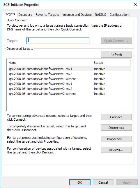
2. Select the Witness target from the local server and click Connect.
3. Enable checkboxes as shown in the image below. Click Advanced.
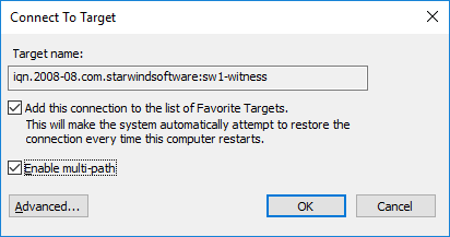
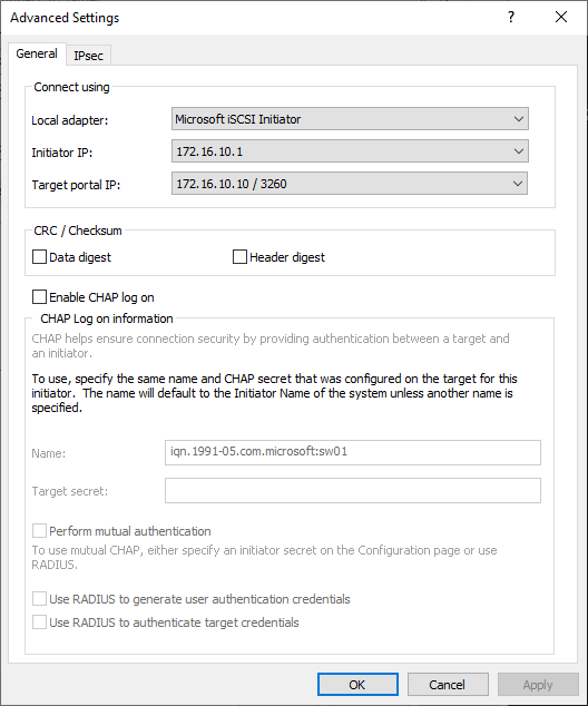
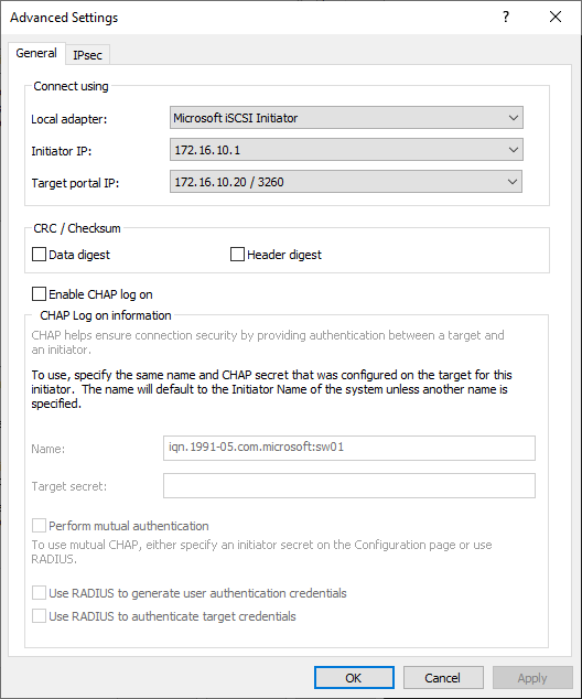
4. Select Microsoft iSCSI Initiator in the Local adapter dropdown menu. In the Initiator IP field, select the IP address for the Data network. In the Target portal IP, select the portal IP from the same subnet. Confirm the actions.
5. Repeat the steps 2-4 to connect the Witness target from the partner node.
Advanced settings should look like in the picture below with the target portal IP 172.16.10.20:
6. Select the CSV1 target discovered from the local server and click Connect.
7. Enable checkboxes as shown in the image below. Click Advanced.
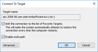
8. Select Microsoft iSCSI Initiator in the Local adapter dropdown menu. In Target portal IP, select 172.16.10.10. Confirm the actions.
9. Select the CSV1 target from the partner StarWind node and click Connect.
10. Enable checkboxes Add this connection to the list of Favorite Targets… and Enable multi-path. Click Advanced.
11. Select Microsoft iSCSI Initiator in the Local adapter dropdown menu. In the Initiator IP field, select the IP address for the Data network. In the Target portal IP, select the portal IP from the same subnet. Confirm the actions.
12. Repeat the steps 1-11 for all remaining HA device targets.
13. Repeat steps 1-12 on the other StarWind node, specifying corresponding Data network IP addresses.
NOTE: Multiple (2,3 or 4) identical iSCSI connections to the same target might be configured depending on the network throughput used for Data and Replication, underlying storage performance, or CPU performance.
Configuring Multipath
It is recommended to configure the different MPIO policies depending on iSCSI channel throughput. It is recommended to set Least Queue Depth MPIO load balancing policy.
NOTE: Different MPIO policies can be set depending on the network throughput, storage performance or setup peculiarities.
1. Configure the MPIO policy for each target with the load balance policy of choice. Select the Target located on the local server and click Devices.
2. In the Devices dialog, click MPIO.
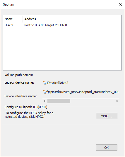
3. Select the appropriate load balancing policy.
4. Repeat the steps 1-3 for configuring the MPIO policy for each remaining device on the current node and on the partner node.
Connecting Disks to Servers
1. Open the Disk Management snap-in. The StarWind disks will appear as unallocated and offline.

2. Bring the disks online by right-clicking on them and selecting the Online menu option.
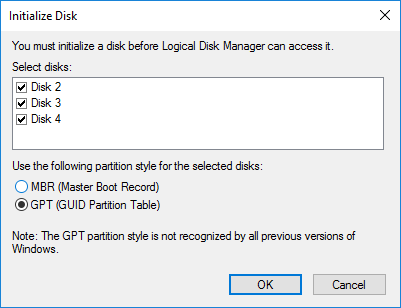
3. Select the CSV disk (check the disk size to be sure) and right-click on it to initialize.
4. By default, the system will offer to initialize all non-initialized disks. Use the Select Disks area to choose the disks. Select GPT (GUID Partition Style) for the partition style to be applied to the disks. Press OK to confirm.
5. Right-click on the selected disk and choose New Simple Volume.
6. In New Simple Volume Wizard, indicate the volume size. Click Next.
7. Assign a drive letter to the disk. Click Next.
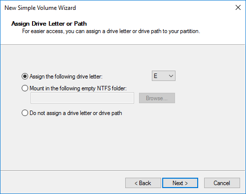
8. Select NTFS in the File System dropdown menu. Keep Allocation unit size as Default. Set the Volume Label of choice. Click Next.
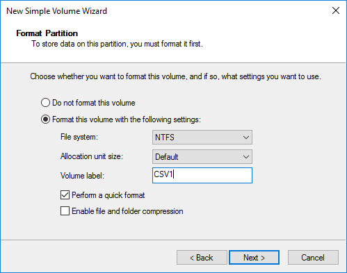
9. Press Finish to complete.
10. Complete the steps 1-9 for the Witness disk. Do not assign any drive letter or drive path for it.
11. On the partner node, open the Disk Management snap-in. All StarWind disks will appear offline. If the status is different from the one shown below, click Action->Refresh in the top menu to update the information about the disks.
12. Repeat steps from the 2nd to bring all the remaining StarWind disks online.
Creating a Failover Cluster in Windows Server
NOTE: To avoid issues during the cluster validation configuration, it is recommended to install the latest Microsoft updates on each node.
NOTE: Server Manager can be opened on the server with desktop experience enabled (necessary features should be installed). Alternatively, the Failover cluster can be managed with Remote Server Administration Tools:
https://docs.microsoft.com/en-us/windows-server/remote/remote-server-administration-tools
NOTE: For converged deployment (SAN & NAS running as a dedicated storage cluster) the Microsoft Failover Cluster is deployed on separate computing nodes. Additionally, for the converged deployment scenario, the storage nodes that host StarWind SAN & NAS as CVM or bare metal do not require a domain controller and Failover Cluster to operate.
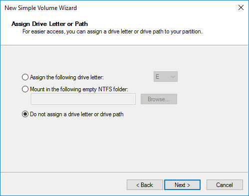
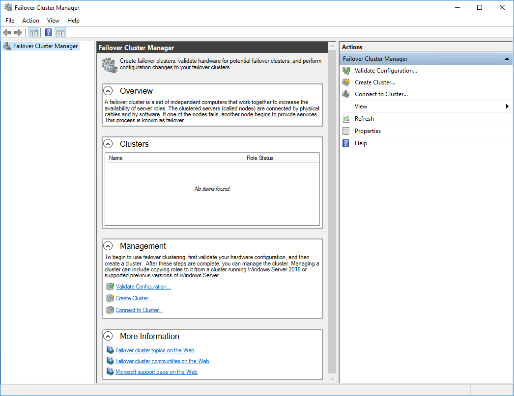
1. Open Server Manager. Select the Failover Cluster Manager item from the Tools menu.
2. Click the Create Cluster link in the Actions section of Failover Cluster Manager.
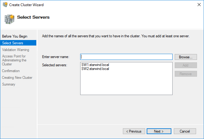
3. Specify the servers to be added to the cluster. Click Next to continue.
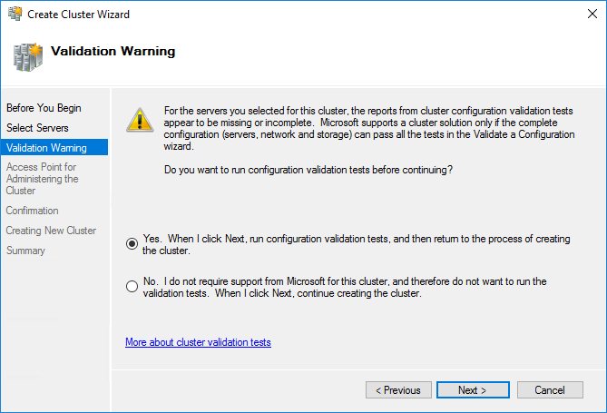
4. Validate the configuration by running the cluster validation tests: select Yes… and click Next to continue.
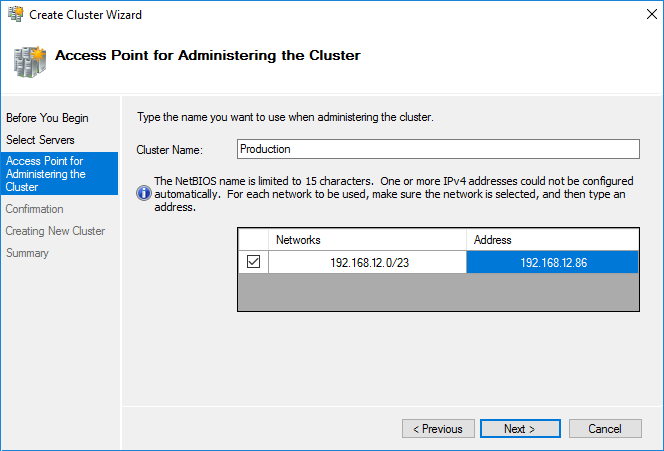
5. Specify the cluster name.
NOTE: If the cluster servers get IP addresses over DHCP, the cluster also gets its IP address over DHCP. If the IP addresses are set statically, set the cluster IP address manually.
6. Make sure that all settings are correct. Click Previous to make any changes or Next to proceed.
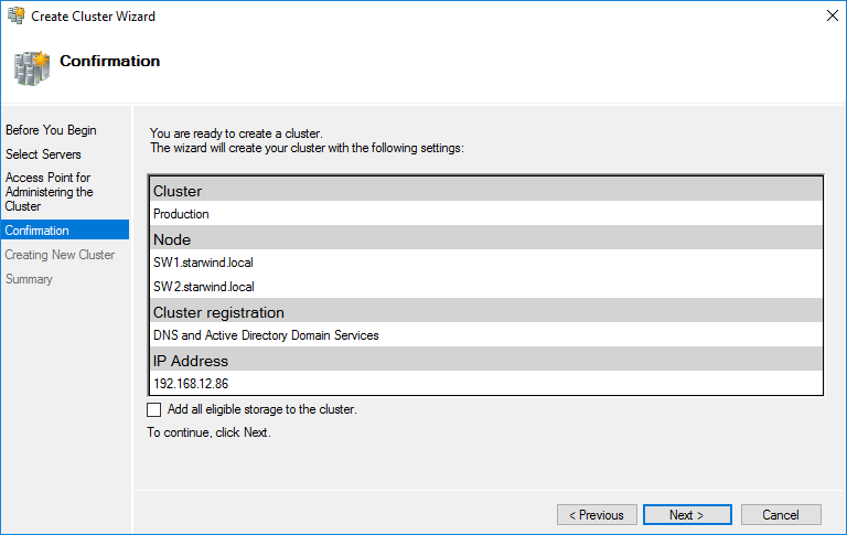
NOTE: If checkbox Add all eligible storage to the cluster is selected, the wizard will add all disks to the cluster automatically. The device with the smallest storage volume will be assigned as a Witness. It is recommended to uncheck this option before clicking Next and add cluster disks and the Witness drive manually.
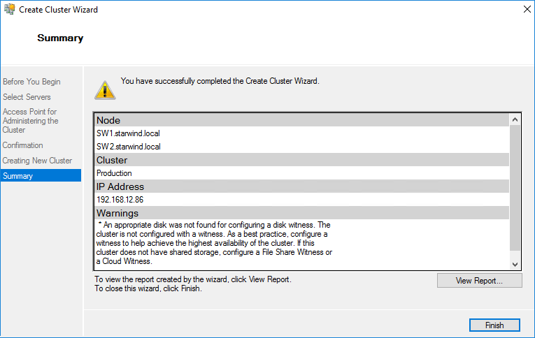
7. The process of the cluster creation starts. Upon the completion, the system displays the summary with the detailed information. Click Finish to close the wizard.
Adding Storage to the Cluster
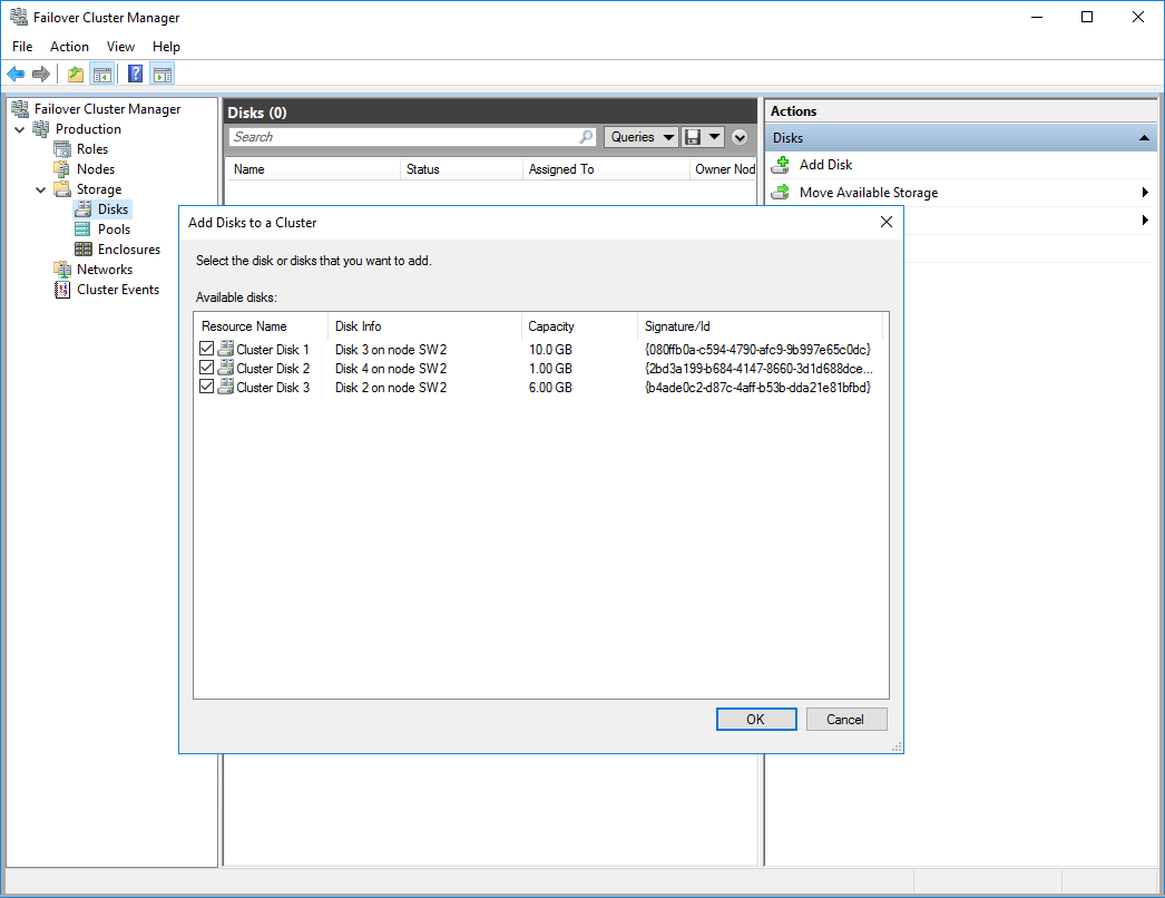
1. In Failover Cluster Manager, navigate to Cluster -> Storage -> Disks. Click Add Disk in the Actions panel, choose StarWind disks from the list and confirm the selection.
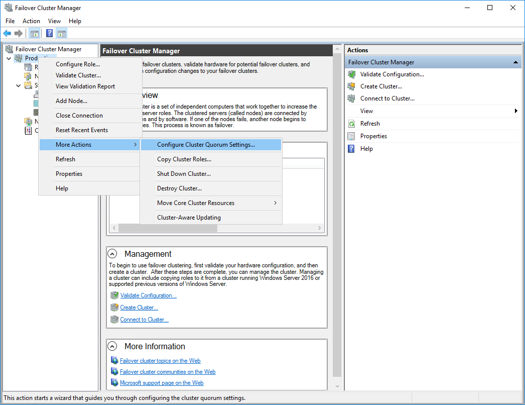
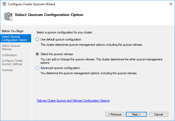
2. To configure the cluster witness disk, right-click on Cluster and proceed to More Actions -> Configure Cluster Quorum Settings.
3. Follow the wizard and use the Select the quorum witness option. Click Next.
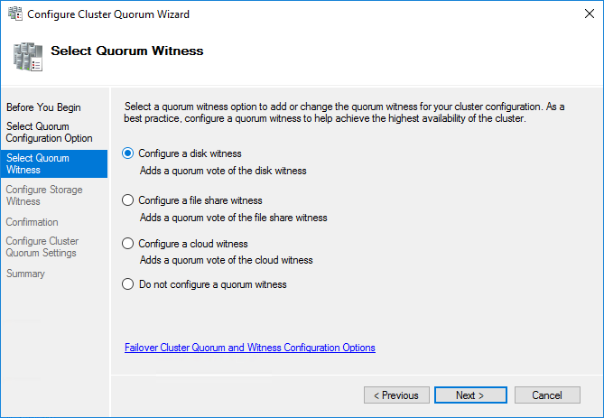
4. Select Configure a disk witness. Click Next.
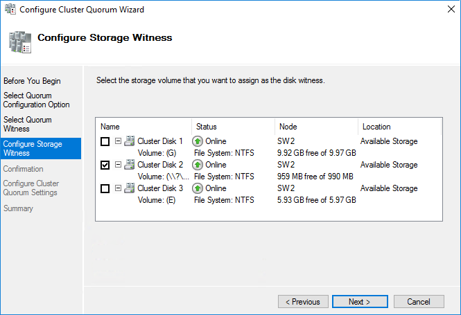
5. Select the Witness disk to be assigned as the cluster witness disk. Click Next and press Finish to complete the operation.
6. In Failover Cluster Manager, Right-click the disk and select Add to Cluster Shared Volumes.
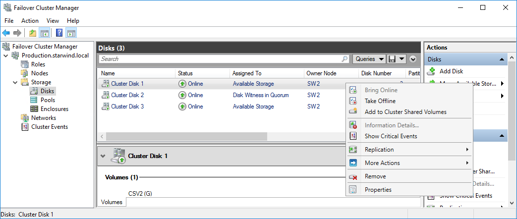
7. If renaming of the cluster shared volume is required, right-click on the disk and select Properties. Type the new name for the disk and click Apply followed by OK.
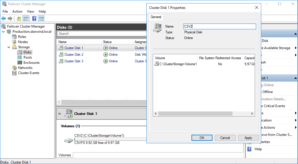
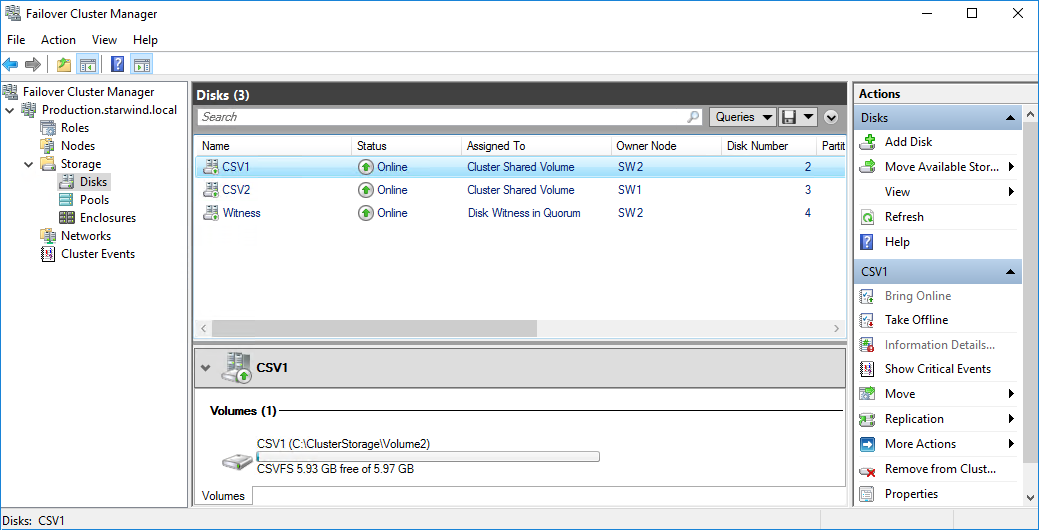
8. Perform the steps 6-7 for any other disk in Failover Cluster Manager. The resulting list of disks will look similar to the screenshot below.
Configuring Cluster Network Preferences
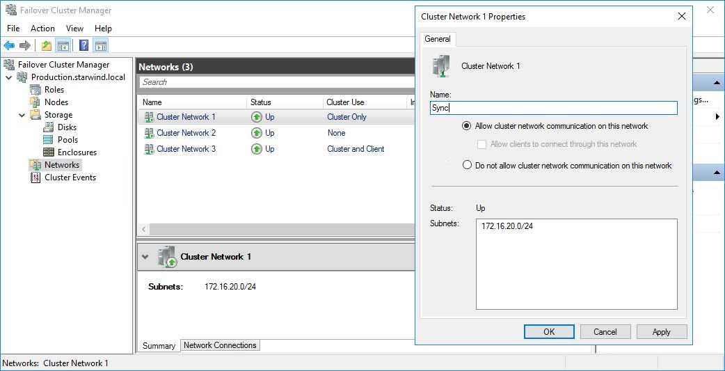
1. In the Networks section of the Failover Cluster Manager, right-click on the network from the list. Set its new name if required to identify the network by its subnet. Apply the change and press OK.
NOTE: Double-check that cluster communication is configured with redundant networks:
https://docs.microsoft.com/en-us/windows-server/failover-clustering/smb-multichannel
2. Rename other networks as described above, if required.
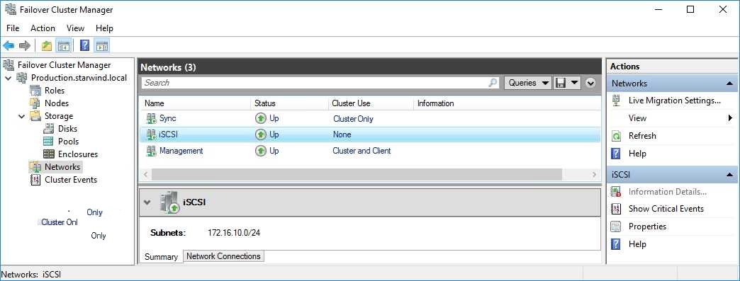
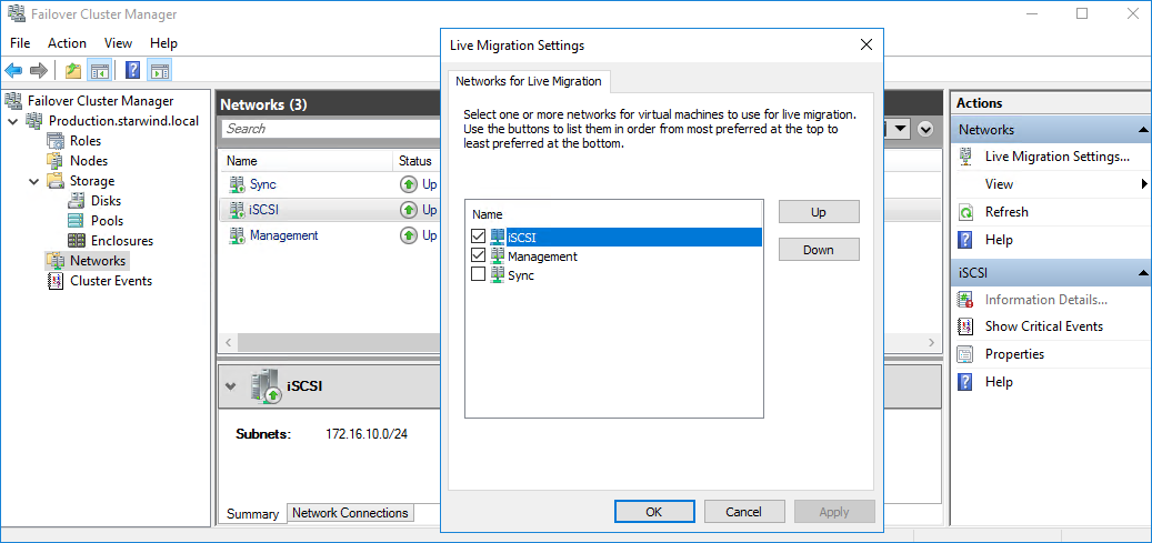
3. In the Actions tab, click Live Migration Settings. Uncheck the synchronization network, while the iSCSI network can be used if it is 10+ Gbps. Apply the changes and click OK.
The cluster configuration is completed and it is ready for virtual machines deployment. Select Roles and in the Action tab, click Virtual Machines -> New Virtual Machine. Complete the wizard.
Configuring File Shares
Please follow the steps below if file shares should be configured on cluster nodes.
Configuring the Scale-Out File Server Role
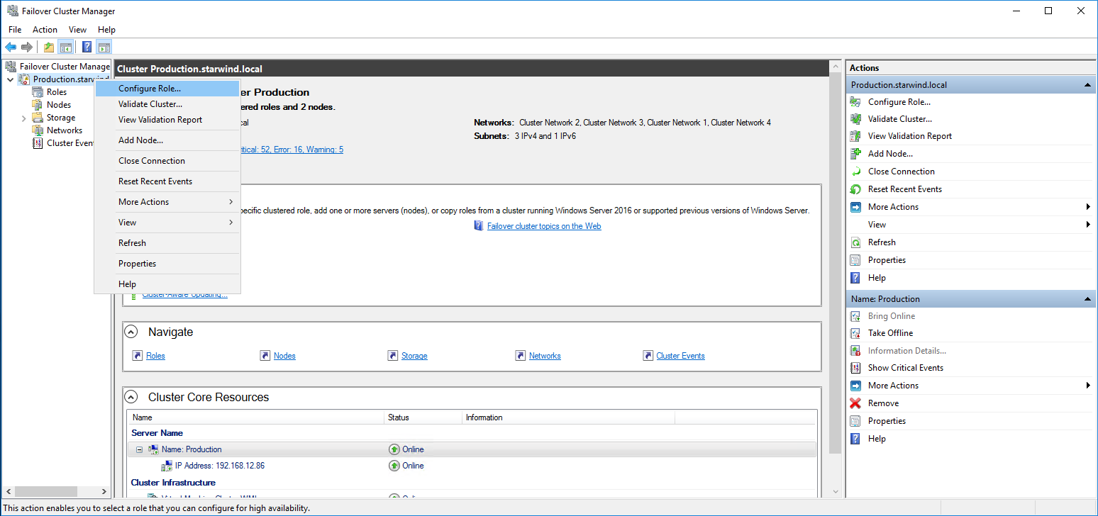
1. To configure the Scale-Out File Server Role, open Failover Cluster Manager.
2. Right-click the cluster name, then click Configure Role and click Next to continue.
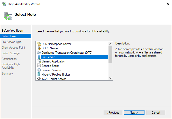
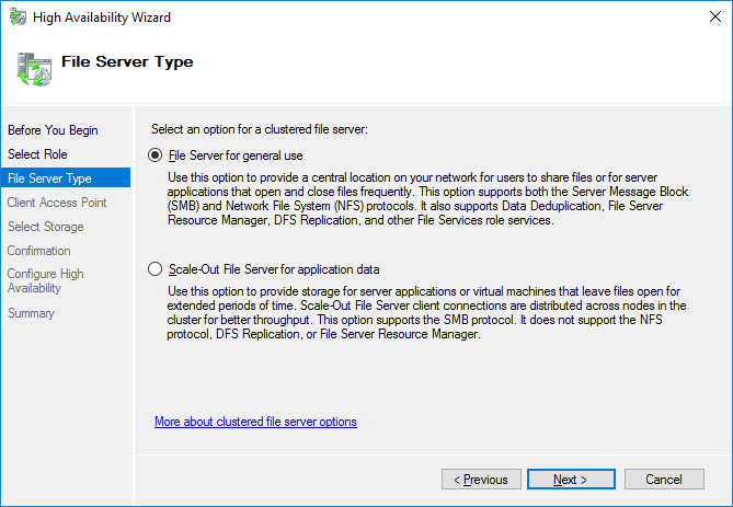
3. Select the File Server item from the list in High Availability Wizard and click Next to continue.
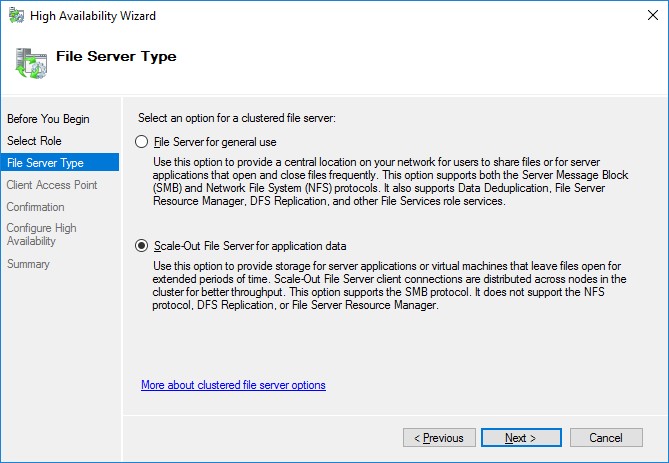
4. Select Scale-Out File Server for application data and click Next.
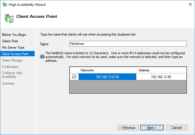
5. On the Client Access Point page, in the Name text field, type the NetBIOS name that will be used to access a Scale-Out File Server.
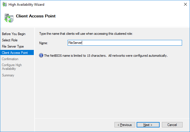
Click Next to continue.
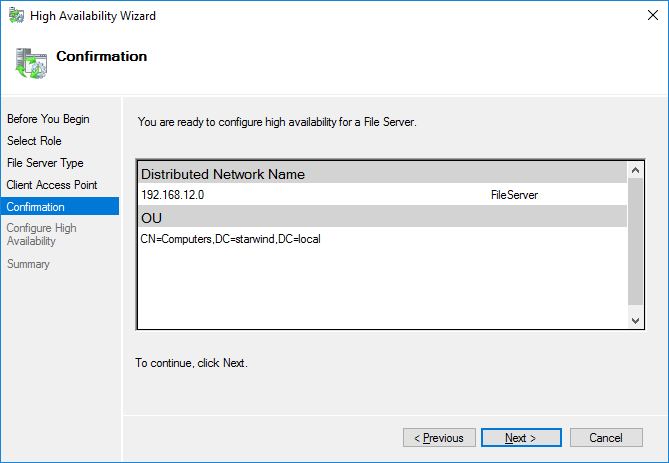
6. Check whether the specified information is correct. Click Next to continue or Previous to change the settings.
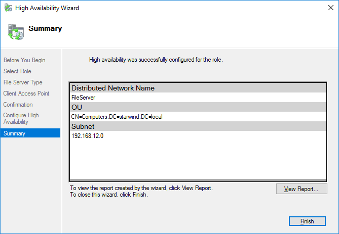
7. Once the installation is finished successfully, the Wizard should now look like the screenshot below.
Click Finish to close the Wizard.
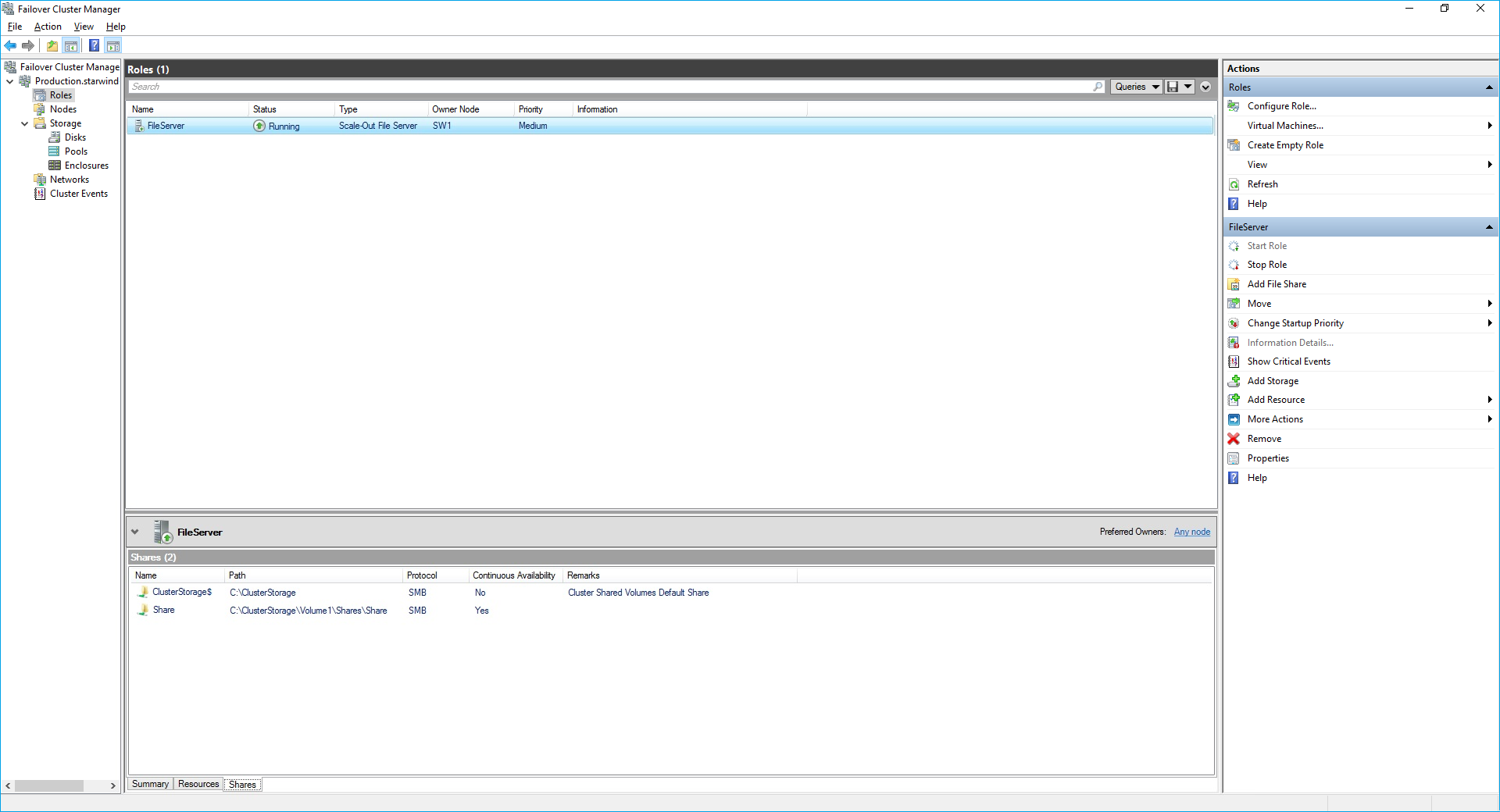
8. The newly created role should now look like the screenshot below.

NOTE: If the role status is Failed and it is unable to Start, please, follow the next steps:
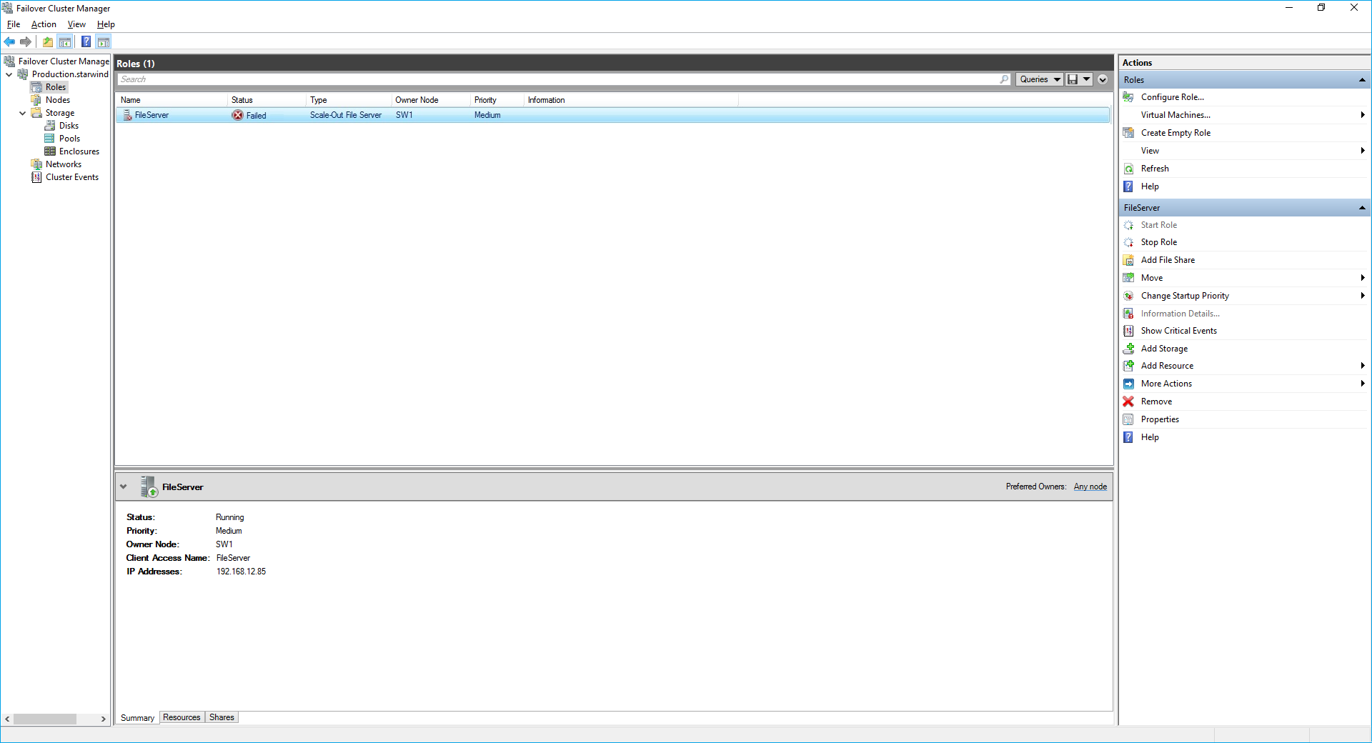
- open Active Directory Users and Computers
- enable the Advanced view if it is not enabled
- edit the properties of the OU containing the cluster computer object (in this case – Production)
- open the Security tab and click Advanced
- in the appeared window, press Add (the Permission Entry dialog box opens), click Select a principal
- in the appeared window, click Object Types, select Computers, and click OK
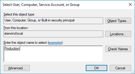
- enter the name of the cluster computer object (in this case – Production)
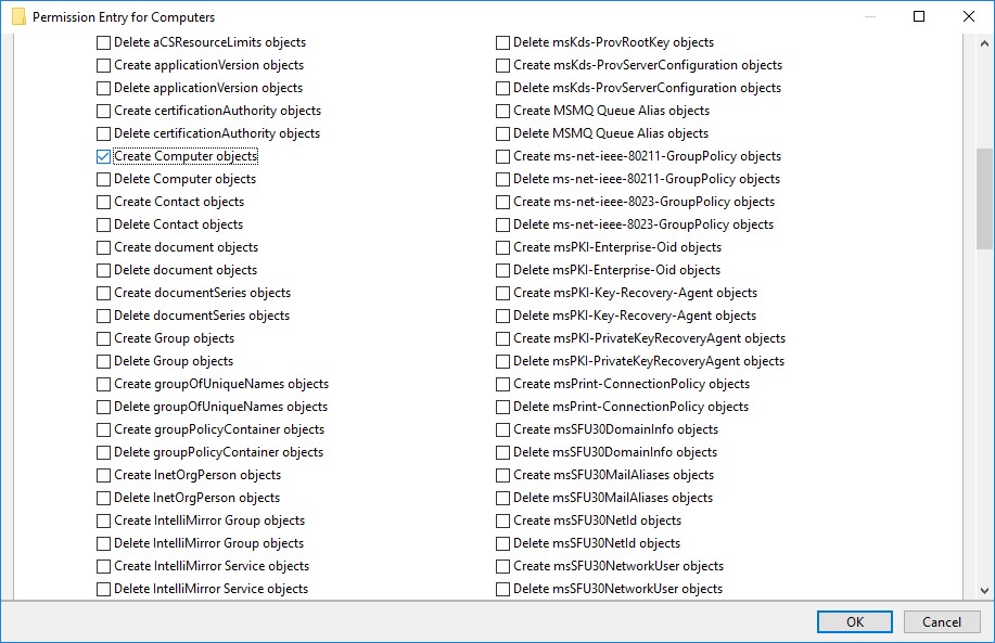
- go back to Permission Entry dialog, scroll down, and select Create Computer Objects,
- click OK on all opened windows to confirm the changes
- open Failover Cluster Manager, right-click SOFS role and click Start Role
Configuring File Share
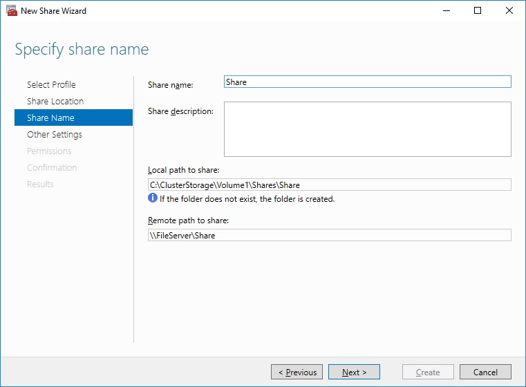
To Add File Share:
- open Failover Cluster Manager
- expand the cluster and then click Roles
- right-click the file server role and then press Add File Share
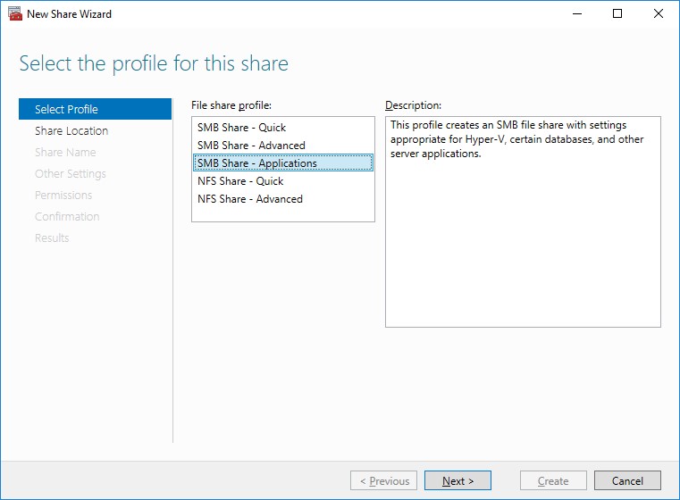
- on the Select the profile for this share page, click SMB Share – Applications and then click Next
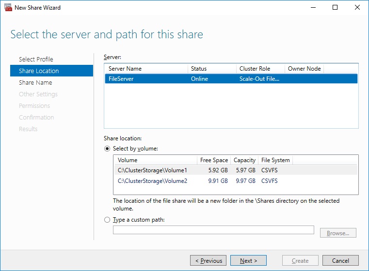
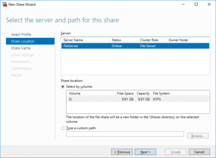
5. Select a CSV to host the share. Click Next to proceed.
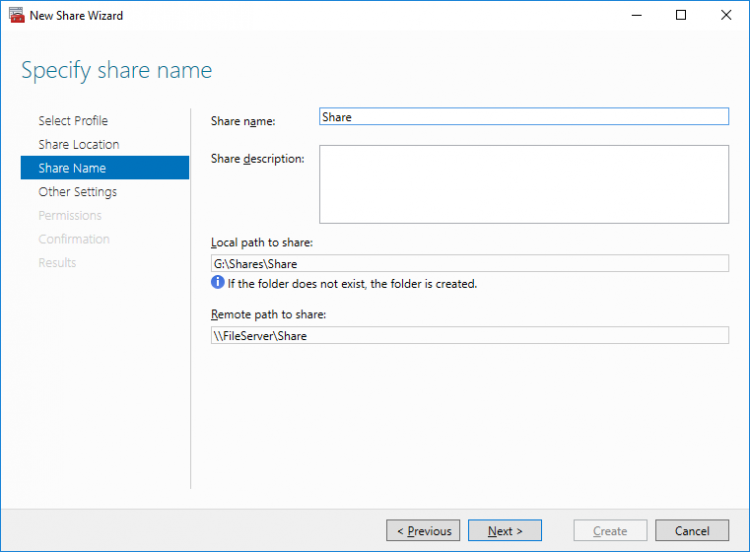
6. Type in the file share name and click Next.
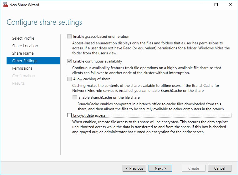
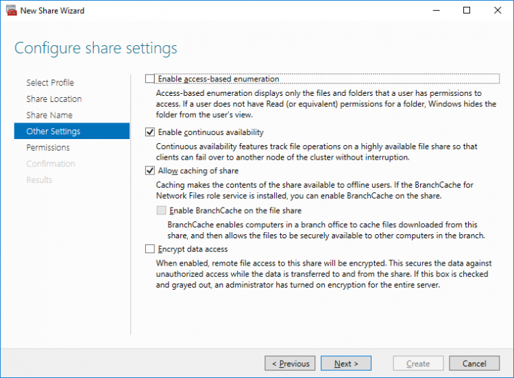
7. Make sure that the Enable Continuous Availability box is checked. Click Next to proceed.
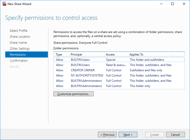
8. Specify the access permissions for the file share.
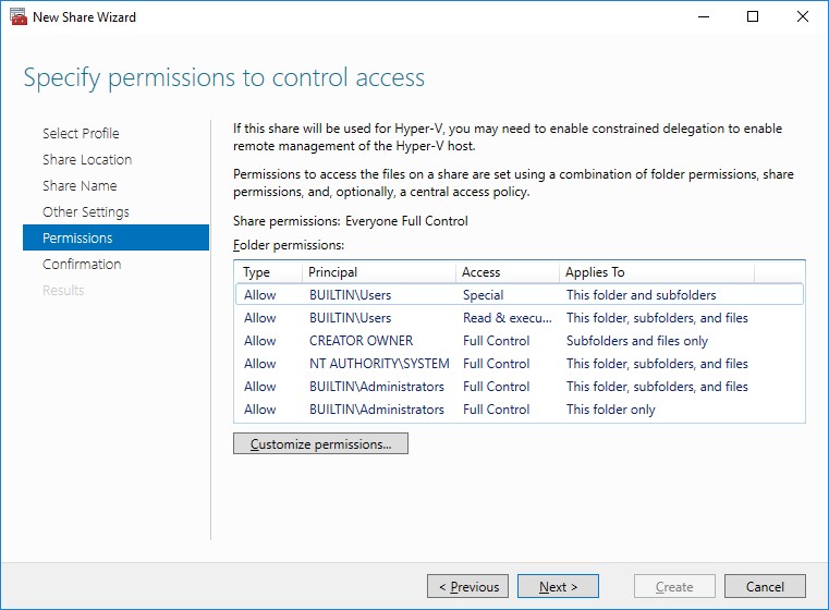
NOTE:
- for the Scale-Out File Server for Hyper-V, all Hyper-V computer accounts, the SYSTEM account, and all Hyper-V administrators must be provided with the full control on the share and file system
- for the Scale-Out File Server on Microsoft SQL Server, the SQL Server service account must be granted full control on the share and the file system
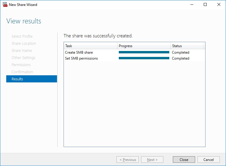
9. Check whether specified settings are correct. Click Previous to make any changes or click Create to proceed.
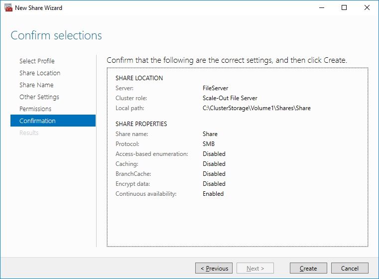
10. Check the summary and click Close to close the Wizard.
To Manage Created File Shares:
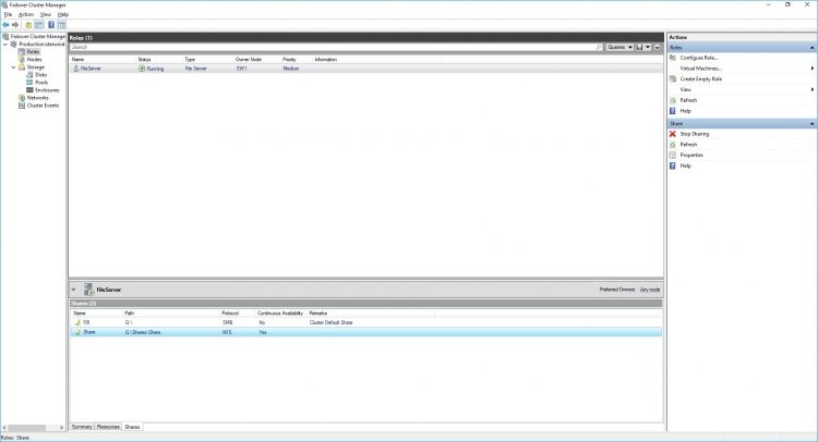
- open Failover Cluster Manager
- expand the cluster and click Roles
- choose the file share role, select the Shares tab, right-click the created file share, and select Properties:
Configuring the File Server for General Use Role
NOTE: To configure File Server for General Use, the cluster should have available storage
1. To configure the File Server for General Use role, open Failover Cluster Manager.
2. Right-click on the cluster name, then click Configure Role and click Next to continue.
3. Select the File Server item from the list in High Availability Wizard and click Next to continue.
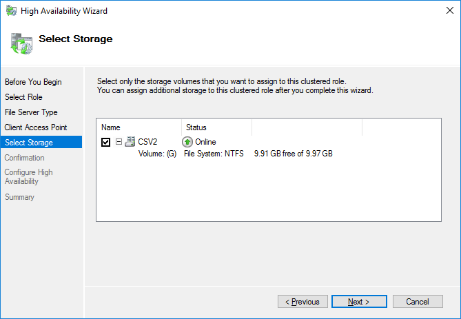
4. Select File Server for general use and click Next.
5. On the Client Access Point page, in the Name text field, type the NETBIOS name that will be used to access the File Server and IP for it.
Click Next to continue.
6. Select the Cluster disk and click Next.
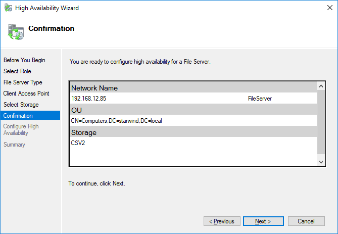
7. Check whether the specified information is correct. Click Next to proceed or Previous to change the settings.
8. Once the installation has been finished successfully, the Wizard should now look like the screenshot below.
Click Finish to close the Wizard.
9. The newly created role should now look like the screenshot below.

NOTE: If the role status is Failed and it is unable to Start, please, follow the next steps:
- open Active Directory Users and Computers
- enable the Advanced view if it is not enabled
- edit the properties of the OU containing the cluster computer object (in this case – Production)
- open the Security tab and click Advanced
- in the appeared window, press Add (the Permission Entry dialog box opens), click Select a principal
- in the appeared window, click Object Types, select Computers, and click OK
- enter the name of the cluster computer object (in this case – Production)
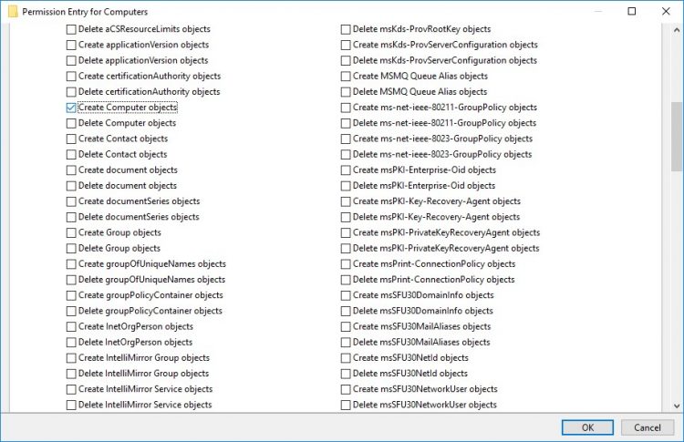
- go back to Permission Entry dialog, scroll down, and select Create Computer Objects
- click OK on all opened windows to confirm the changes
- open Failover Cluster Manager, right-click File Share role and click Start Role
Configuring SMB File Share
To Add SMB File Share
1. Open Failover Cluster Manager.
2. Expand the cluster and then click Roles.
3. Right-click the File Server role and then press Add File Share.
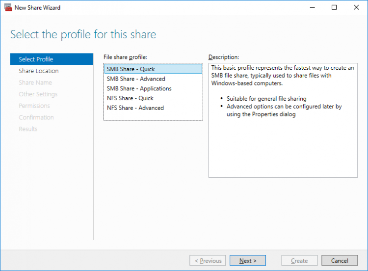
4. On the Select the profile for this share page, click SMB Share – Quick and then click Next.
5. Select available storage to host the share. Click Next to continue.
6. Type in the file share name and click Next.
7. Make sure that the Enable Continuous Availability box is checked. Click Next to continue.
8.Specify the access permissions for the file share.
9. Check whether specified settings are correct. Click Previous to make any changes or Next/Create to continue.

10. Check the summary and click Close.

To manage created SMB File Shares
11. Open Failover Cluster Manager.
12. Expand the cluster and click Roles.
13. Choose the File Share role, select the Shares tab, right-click the created file share, and select Properties.
Configuring NFS file share
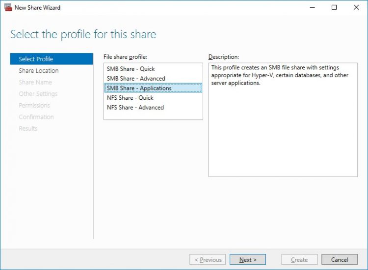
To Add NFS File Share
1. Open Failover Cluster Manager.
2. Expand the cluster and then click Roles.
3. Right-click the File Server role and then press Add File Share.
4. On the Select the profile for this share page, click NFS Share – Quick and then click Next.
5. Select available storage to host the share. Click Next to continue.
6. Type in the file share name and click Next.
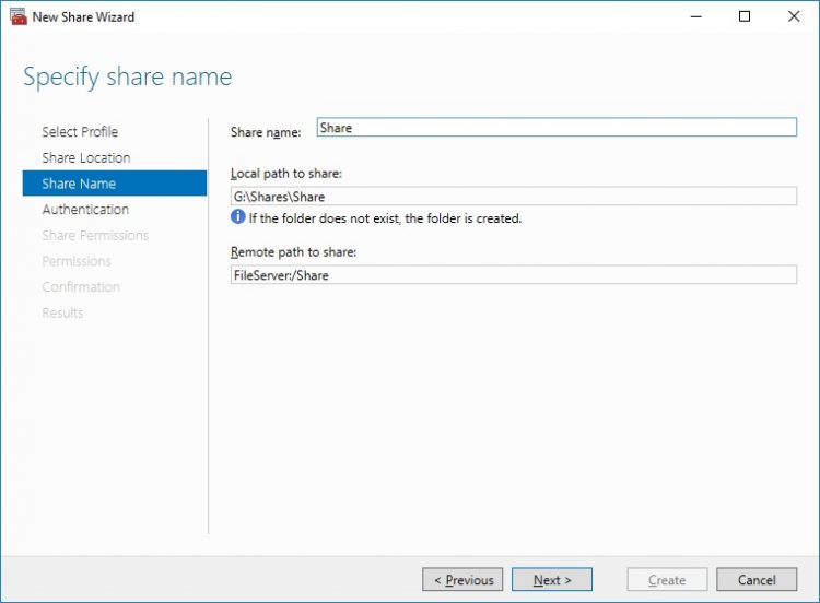
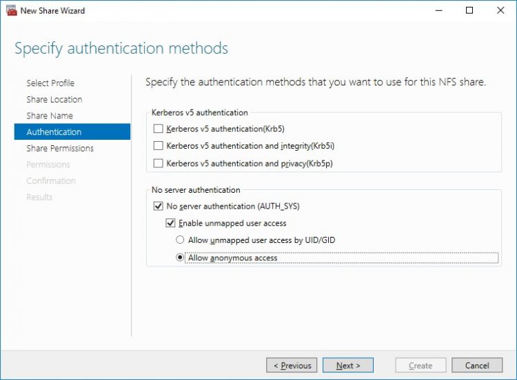
7. Specify the Authentication. Click Next and confirm the message in pop-up window to continue.
8. Click Add and specify Share Permissions.
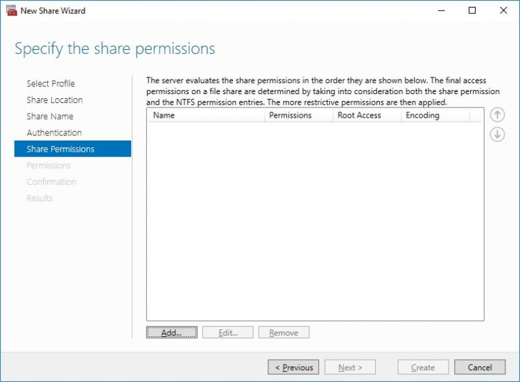
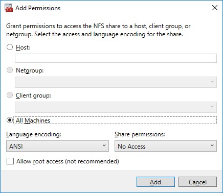
9. Specify the access permissions for the file share.
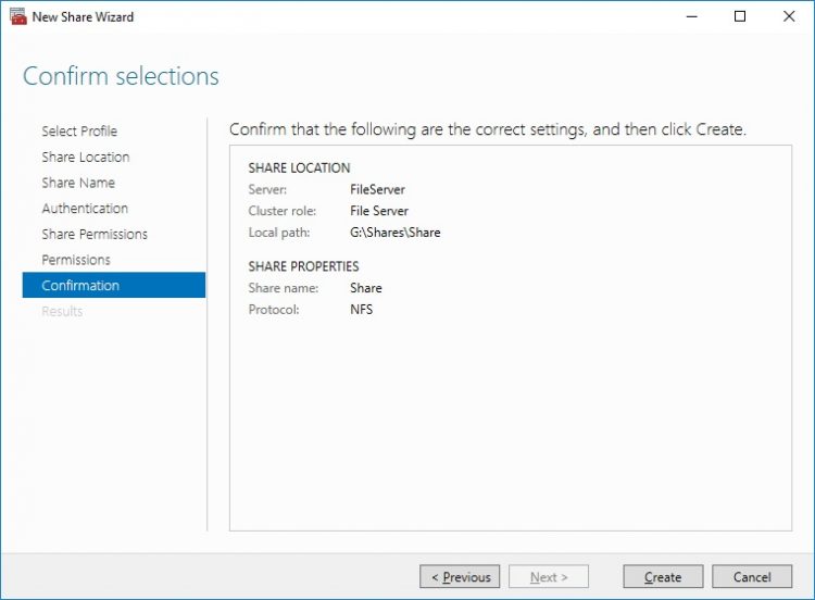
10. Check whether specified settings are correct. Click Previous to make any changes or click Create to continue.
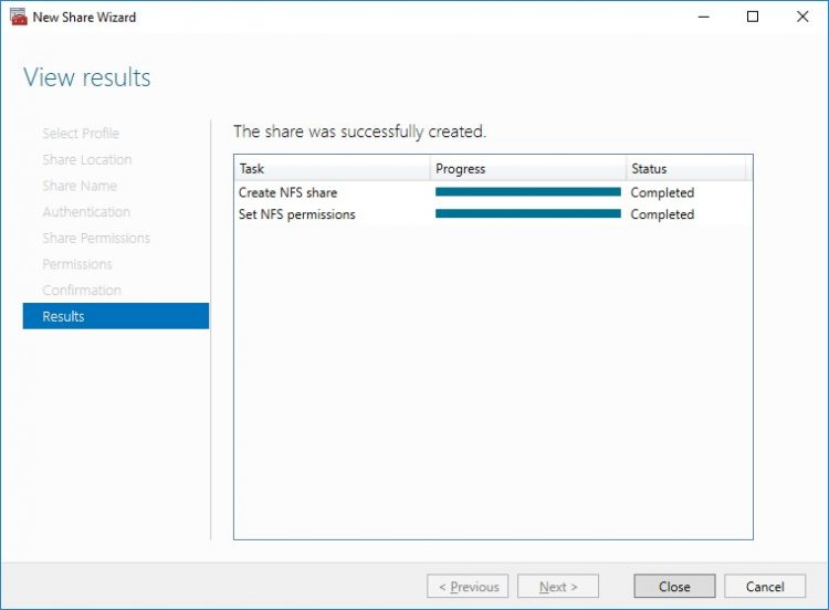
11. Check a summary and click Close to close the Wizard.
To manage created NFS File Shares:
- open Failover Cluster Manager
- expand the cluster and click Roles
- choose the File Share role, select the Shares tab, right-click the created file share, and select Properties
Conclusion
Following this guide, a 2-node Failover Cluster was deployed and configured with StarWind Virtual SAN (VSAN) running in a CVM on each host. As a result, a virtual shared storage “pool” accessible by all cluster nodes was created for storing highly available virtual machines.
