

StarWind Virtual SAN®
Providing HA storage repositories for XenServer 7.x
- January 20, 2021
- 19 min read
- Download as PDF
Introduction
Traditionally XenServer Pool requires shared storage to guarantee data safety, allow virtual machines migration, enable continuous application availability and eliminate any single point of failure within an IT environment.
NOTE: Hyperconverged scenario is not officially supported with Citrix XenServer.
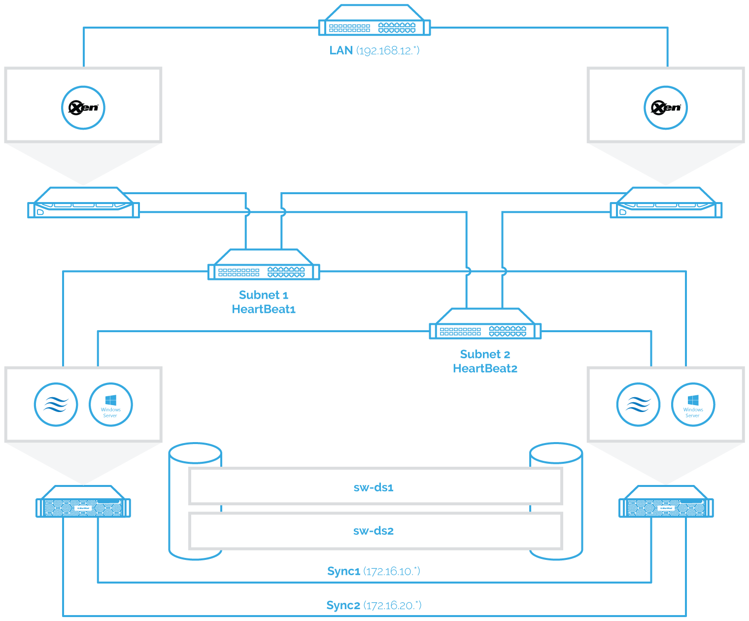
The network diagram below illustrates the system configuration.
StarWind VSAN System Requirements
Prior to installing StarWind Virtual SAN, please make sure that the system meets the requirements, which are available via the following link:
https://www.starwindsoftware.com/system-requirements
Recommended RAID settings for HDD and SSD disks:
https://knowledgebase.starwindsoftware.com/guidance/recommended-raid-settings-for-hdd-and-ssd-disks/
Please read StarWind Virtual SAN Best Practices document for additional information:
https://www.starwindsoftware.com/resource-library/starwind-virtual-san-best-practices
Installing StarWind VSAN for Hyper-V
1. Download the StarWind setup executable file from the StarWind website:
https://www.starwind.com/registration-starwind-virtual-san
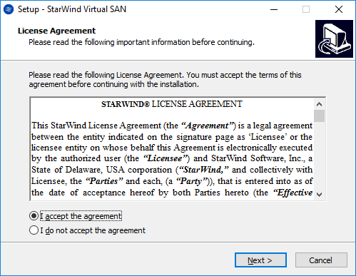
2. Launch the downloaded setup file on the server to install StarWind Virtual SAN or one of its components. The Setup wizard will appear. Read and accept the License Agreement.
3. Carefully read the information about the new features and improvements. Red text indicates warnings for users that are updating the existing software installations.
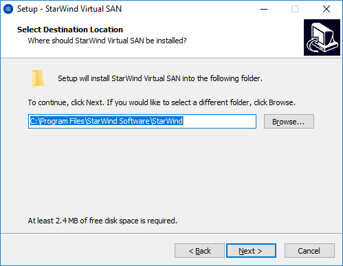
4. Select Browse to modify the installation path if necessary. Click on Next to continue.
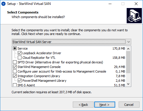
5. Select the following components for the minimum setup:
- StarWind Virtual SAN Service. The StarWind Virtual SAN service is the “core” of the software. It can create iSCSI targets as well as share virtual and physical devices. The service can be managed from StarWind Management Console on any Windows computer that is on the same network. Alternatively, the service can be managed from StarWind Web Console deployed separately.
- StarWind Management Console. Management Console is the Graphic User Interface (GUI) part of the software that controls and monitors all storage-related operations (e.g., allows users to create targets and devices on StarWind Virtual SAN servers connected to the network).
NOTE: To manage StarWind Virtual SAN installed on a Windows Server Core edition with no GUI, StarWind Management Console should be installed on a different computer running the GUI-enabled Windows edition.
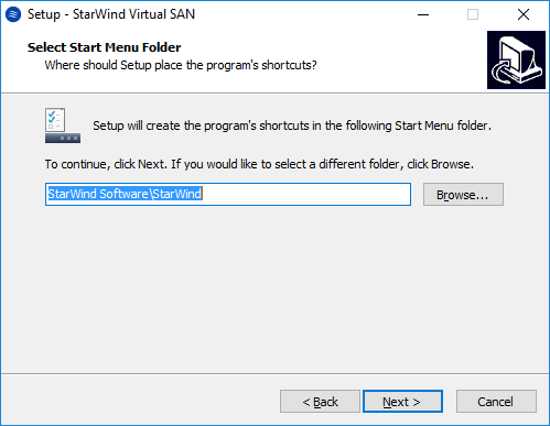
6. Specify Start Menu Folder.
7. Enable the checkbox if a desktop icon needs to be created. Click on Next to continue.
8. When the license key prompt appears, choose the appropriate option:
- request time-limited fully functional evaluation key.
- request FREE version key.
- relect the previously purchased commercial license key.
9. Click on the Browse button to locate the license file.
10. Review the licensing information.
11. Verify the installation settings. Click on Back to make any changes or Install to proceed with installation.
12. Enable the appropriate checkbox to launch StarWind Management Console right after the setup wizard is closed and click on Finish.
13. Repeat the installation steps on the partner node.
Creating StarWind devices
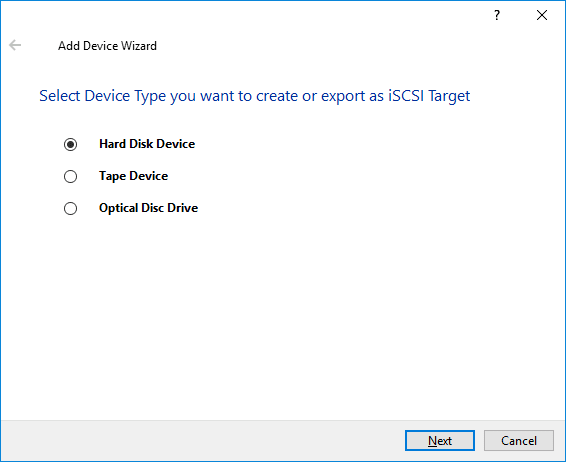
1. In the StarWind Management Console click to Add Device (advanced) button and open Add Device (advanced) Wizard.
2. Select Hard Disk Device as the type of device to be created.
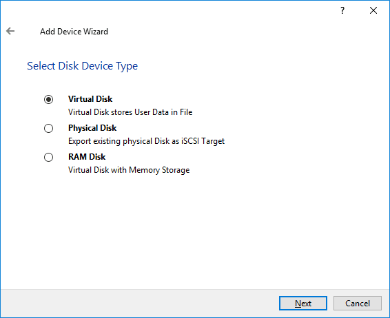
3. Select Virtual Disk.
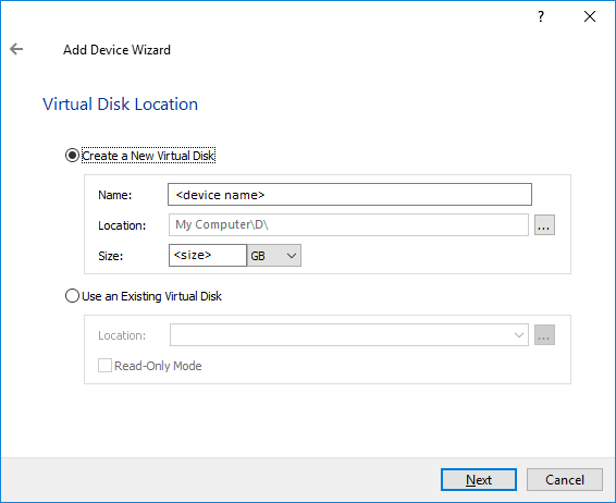
4. Specify a virtual disk Name, Location, and Size.
5. Select the Thick provisioned disk type and block size.
NOTE: Use 4096 sector size for targets, connected on Windows-based systems and 512 bytes sector size for targets, connected on Linux-based systems (ESXi/Xen/KVM).
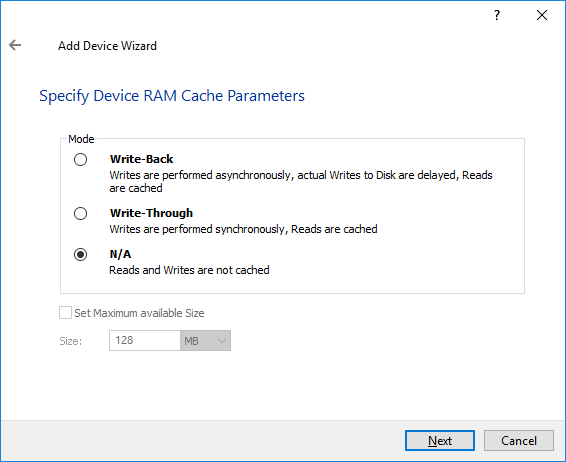
6. Define a caching policy and specify a cache size (in MB). Also, the maximum available cache size can be specified by selecting the appropriate checkbox. Optionally, define the L2 caching policy and cache size.
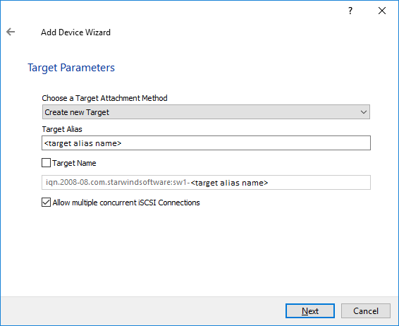
7. Specify Target Parameters. Select the Target Name checkbox to enter a custom target name. Otherwise, the name is generated automatically in accordance with the specified target alias.
8. Click Create to add a new device and attach it to the target.
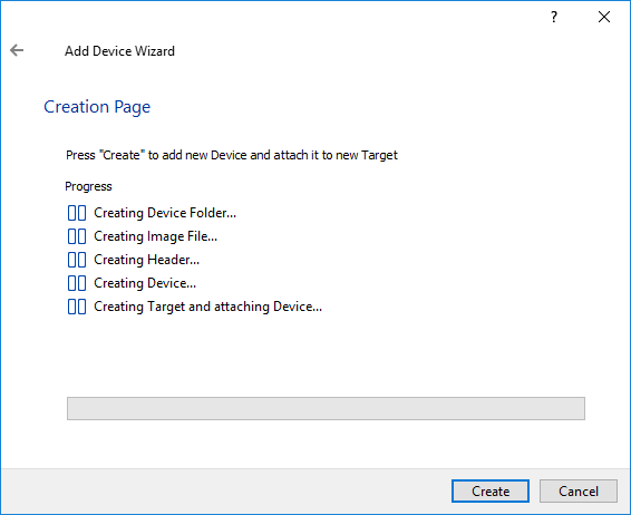
9. Click Close to finish the device creation.
10. The successfully added devices appear in the StarWind Management Console.
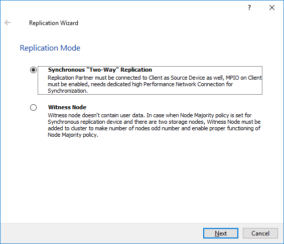
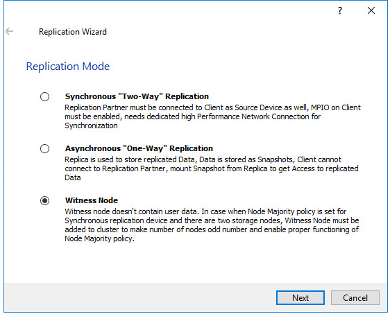
Select the Required Replication Mode
The replication can be configured using Synchronous “Two-Way” Replication mode:
Synchronous or active-active replication ensures real-time synchronization and load balancing of data between two or three cluster nodes. Such a configuration tolerates the failure of two out of three storage nodes and enables the creation of an effective business continuity plan. With synchronous mirroring, each write operation requires control confirmation from both storage nodes. It guarantees the reliability of data transfers but is demanding in bandwidth since mirroring will not work on high-latency networks.
Synchronous “Two-Way” replication
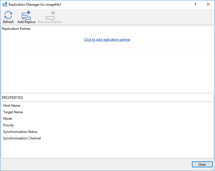
1. Right-click the recently created device and select Replication Manager from the shortcut menu.
2. Select the Add Replica button in the top menu.
3. Select Synchronous “Two-Way” replication as a replication mode.
4. Specify a partner Host name or IP address and Port Number.
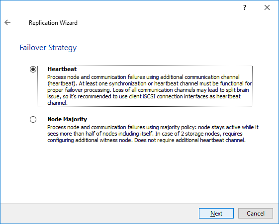
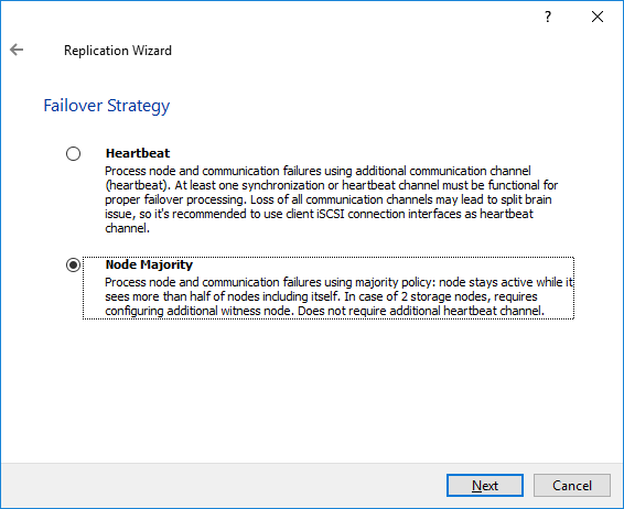
Selecting the Failover Strategy
StarWind provides 2 options for configuring a failover strategy:
Heartbeat
The Heartbeat failover strategy allows avoiding the “split-brain” scenario when the HA cluster nodes are unable to synchronize but continue to accept write commands from the initiators independently. It can occur when all synchronization and heartbeat channels disconnect simultaneously, and the partner nodes do not respond to the node’s requests. As a result, StarWind service assumes the partner nodes to be offline and continues operations on a single-node mode using data written to it.
If at least one heartbeat link is online, StarWind services can communicate with each other via this link. The device with the lowest priority will be marked as not synchronized and get subsequently blocked for the further read and write operations until the synchronization channel resumption. At the same time, the partner device on the synchronized node flushes data from the cache to the disk to preserve data integrity in case the node goes down unexpectedly. It is recommended to assign more independent heartbeat channels during the replica creation to improve system stability and avoid the “split-brain” issue.
With the heartbeat failover strategy, the storage cluster will continue working with only one StarWind node available.
Node Majority
The Node Majority failover strategy ensures the synchronization connection without any additional heartbeat links. The failure-handling process occurs when the node has detected the absence of the connection with the partner.
The main requirement for keeping the node operational is an active connection with more than half of the HA device’s nodes. Calculation of the available partners is based on their “votes”.
In case of a two-node HA storage, all nodes will be disconnected if there is a problem on the node itself, or in communication between them. Therefore, the Node Majority failover strategy requires the addition of the third Witness node or file share (SMB) which participates in the nodes count for the majority, but neither contains data on it nor is involved in processing clients’ requests. In case an HA device is replicated between 3 nodes, no Witness node is required.
With Node Majority failover strategy, failure of only one node can be tolerated. If two nodes fail, the third node will also become unavailable to clients’ requests.
Please select the required option:
Heartbeat
1. Select Failover Strategy.
2. Select Create new Partner Device and click Next.
3. Select a partner device Location.
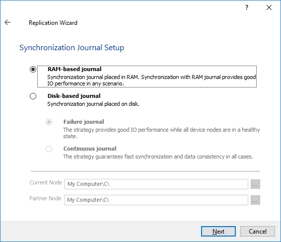
4. Select Synchronization Journal Strategy and click Next.
NOTE: There are several options – RAM-based journal (default) and Disk-based journal with failure and continuous strategy, that allow to avoid full synchronization cases.
RAM-based (default) synchronization journal is placed in RAM. Synchronization with RAM journal provides good I/O performance in any scenario. Full synchronization could occur in the cases described in this KB: https://knowledgebase.starwindsoftware.com/explanation/reasons-why-full-synchronization-may-start/
Disk-based journal placed on a separate disk from StarWind devices. It allows to avoid full synchronization for the devices where it’s configured even when StarWind service is being stopped on all nodes. Disk-based synchronization journal should be placed on a separate, preferably faster disk from StarWind devices. SSDs and NVMe disks are recommended as the device performance is defined by the disk speed, where the journal is located. For example, it can be placed on the OS boot volume.
It is required to allocate 2 MB of disk space for the synchronization journal per 1 TB of HA device size with a disk-based journal configured with 2-way replication and 4MB per 1 TB of HA device size for 3-way replication.
Failure journal
The strategy provides good I/O performance, as a RAM-based journal, while all device nodes are in a healthy synchronized state. If a device on one node went into a not synchronized state, the disk-based journal activates and a performance drop could occur as the device performance is defined by the disk speed, where the journal is located. Fast synchronization is not guaranteed in all cases. For example, if a simultaneous hard reset of all nodes occurs, full synchronization will occur.
Continuous journal
The strategy guarantees fast synchronization and data consistency in all cases. Although, this strategy has the worst I/O performance, because of frequent write operations to the journal, located on the disk, where the journal is located.
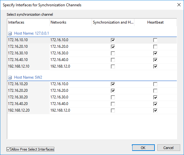
5. Click Change Network Settings.
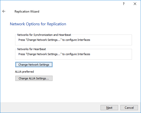
6. Specify the interfaces for Synchronization and Heartbeat Channels. Click OK and then click Next.
7. In Select Partner Device Initialization Mode, select Synchronize from existing Device and click Next.
8. Click Create Replica. Click Finish to close the wizard.
The successfully added device appears in StarWind Management Console.
9. Follow the similar procedure for the creation of other virtual disks that will be used as storage repositories.
Node Majority
There are two ways to configure Witness for 2-nodes StarWind HA device, created with Node Majority Failover Strategy: File Share (SMB) as Witness and additional server as Witness Node.
– Creating HA device with File SHare(SMB) as Witness:
SMB Witness is a file, located on SMB share, which can be accessed by both nodes and help them to eliminate the split-brain issue in case of synchronization connection interruption between the nodes. To set up the SMB file share as a Witness for 2-nodes HA device with Node Majority Failover Strategy, perform the actions, described on this page:
https://www.starwindsoftware.com/help/ConfiguringFileShareSMBasWitness.html
– Creating HA device with Witness Node:
1. Select the Node Majority failover strategy and click Next.
2. Choose Create new Partner Device and click Next.
3. Specify the partner device Location and modify the target name if necessary. Click Next. Select Synchronization Journal strategy and location and click Next.
4. In Network Options for Replication, press the Change network settings button and select the synchronization channel for the HA device.
5. In Specify Interfaces for Synchronization Channels, select the checkboxes with the appropriate networks and click OK. Then click Next.
6. Select Synchronize from existing Device as the partner device initialization mode.
7. Press the Create Replica button and close the wizard.
8. The added devices will appear in StarWind Management Console.
Repeat the steps above to create other virtual disks if necessary.
Adding Witness Node
Witness node can be configured on a separate host or as a virtual machine in a cloud. It requires StarWind Virtual SAN service installed on it.
NOTE: Since the device created in this guide is replicated between 2 active nodes with the Node Majority failover strategy, a Witness node must be added to it.
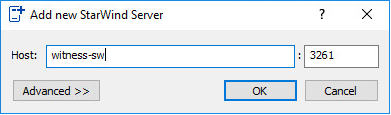
1. Open StarWind Management Console, right-click on the Servers field and press the Add Server button. Add a new StarWind Server which will be used as the Witness node and click OK.
2. Right-click on the HA device with the configured Node Majority failover policy and select Replication Manager and press the Add Replica button.
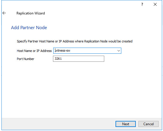
3. Select Witness Node.
4. Specify the Witness node Host Name or IP address. The default Port Number is 3261.
5. In Partner Device Setup, specify the Witness device Location. Optionally, modify the target name by clicking the appropriate button.
6. In Network Options for Replication, select the synchronization channel with the Witness node by clicking the Change Network Settings button.
7. Specify the interface for Synchronization and Heartbeat and click OK.
8. Click Create Replica and then close the wizard.
9. Repeat the steps above to create other virtual disks if necessary.
NOTE: To extend an Image File or a StarWind HA device to the required size, please check the article below:
Configuring Hosts with XenServer 7.x
1. Launch XenCenter.
2. Click New Pool.
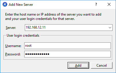
3. Specify the name and description of the pool and click Add New Server.
4. In the Add New Server window, specify the first XenServer host to be added to the pool as well as User name and Password.
5. To add the second XenServer host to the pool, repeat the previous steps.
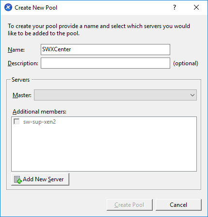
6. Specify the Master host.
7. Click Create Pool.
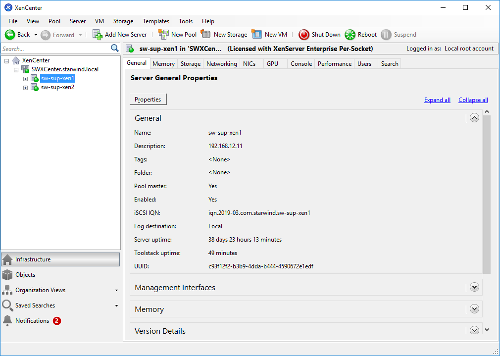
8. After creating the pool, the XenCenter window should look as shown in the screenshot below.
Configuring Network Settings
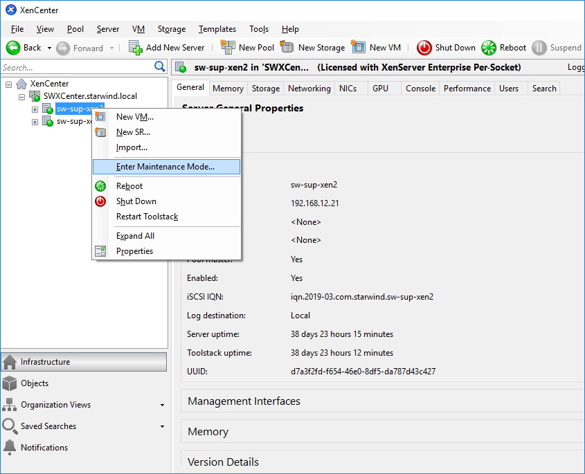
NOTE: To switch the XenServer host to Maintenance Mode for network configuration, right-click the XenServer and select Enter Maintenance Mode… from the shortcut menu.
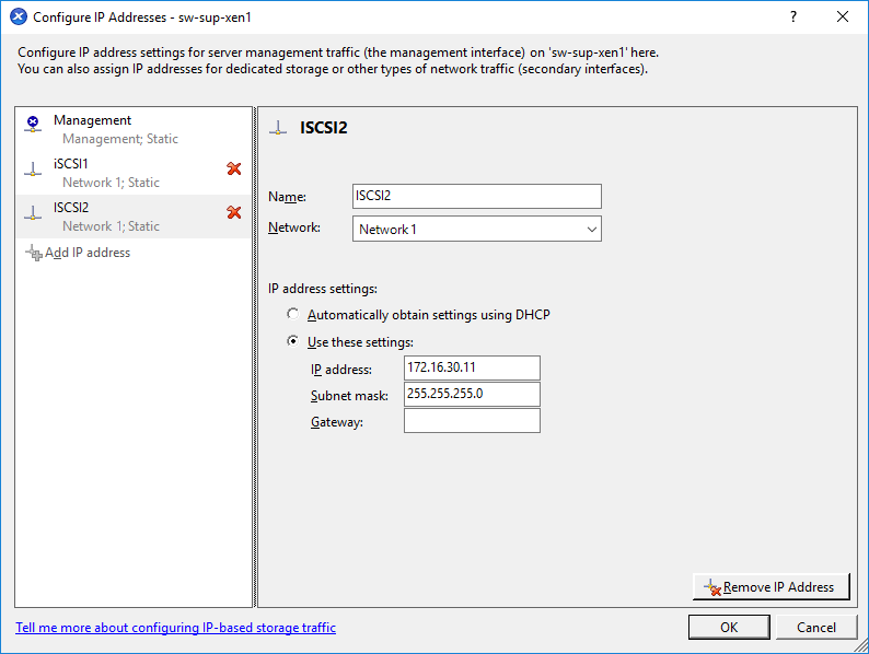
1. Select the first XenServer host, switch to the Networking tab, and click Configure.
2. In the appeared window, click Add IP address to add networks.
3. Configure the required IP address and click OK.
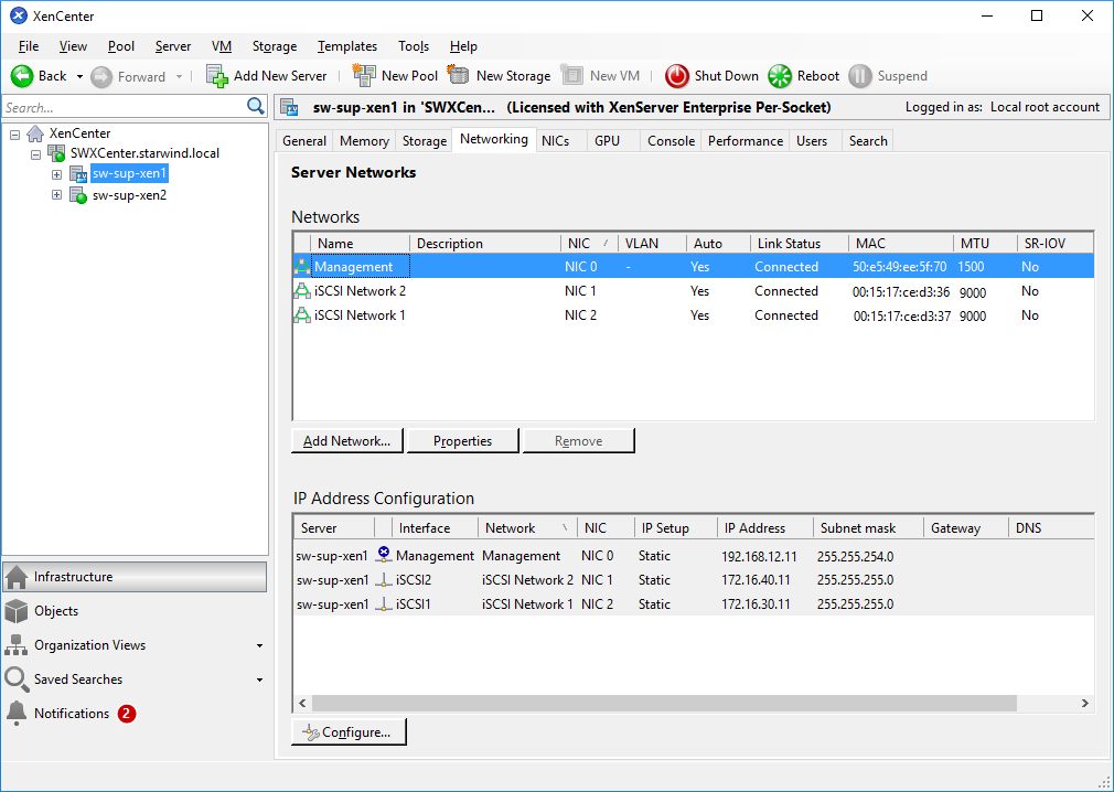
4. The window should look as shown below.
5. Exit the Maintenance mode.
6. Repeat the same steps on all XenServer hosts.
Configuring iSCSI Initiator
NOTE: The following actions should be performed on each XenServer host in the pool.
1. Switch XenServer host to the Maintenance mode for iSCSI configuration.
2. Edit /etc/iscsi/initiatorname.iscsi and set the appropriate iqn for XenServer iSCSI initiator.
3. Edit the /etc/iscsi/iscsid.conf file.
Set the following values:
node.startup = automatic
node.session.iscsi.FirstBurstLength = 262144
node.session.iscsi.MaxBurstLength = 262144
4. Restart the software iSCSI service:
service iscsi restart
service iscsid restart
5. Set the iSCSI services to start automatically when launching XenServer:
chkconfig iscsi on
chkconfig iscsid on
Applying Multipathing
NOTE: The following actions should be performed on each XenServer host in the pool.
1. Switch XenServer host to maintenance mode for multipath configuration
2. Switch to console tab, edit the multipath configuration file by running “vi /etc/multipath.conf” command.
3. Insert the following block into the “devices” section:
device

{

vendor "STARWIND"

product "STARWIND*"

path_grouping_policy multibus

path_checker "tur"

failback immediate

path_selector "round-robin 0"

rr_min_io 3

rr_weight uniform

hardware_handler "1 alua"

}
4. Restart the multipath service:
service multipathd restart

service multipathd reload
5. Set the multipath service to start automatically when launching XenServer:
chkconfig multipathd on
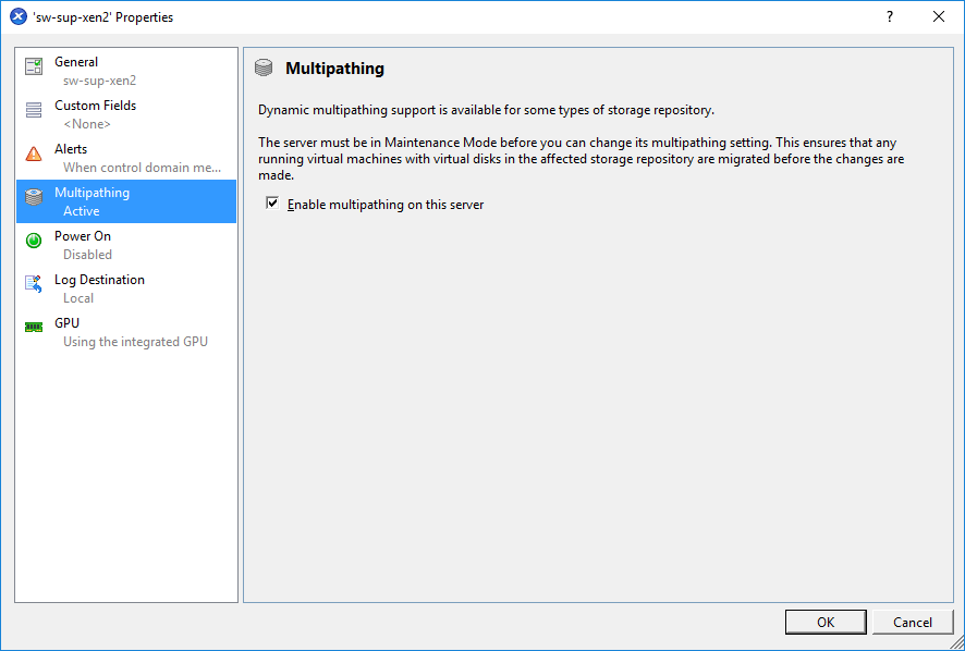
6. Right-click the XenServer and select Properties from the shortcut menu.
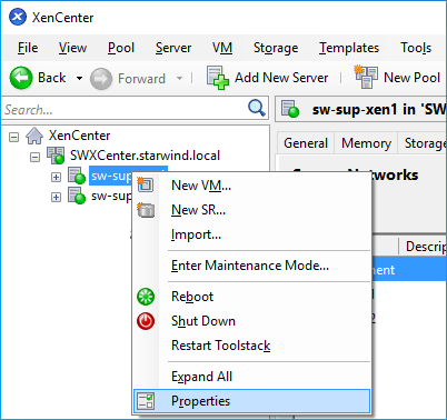
7. Click Multipathing Active in the left pane. Select the Enable multipathing on this server checkbox and click OK.
8. Turn off the Maintenance mode: right-click the XenServer and select Exit Maintenance Mode from the shortcut menu.
9. Reboot the XenServer host.
Adding Shared Storage manually
1. Select the XenServer host. Switch to the Console tab in XenCenter.
2. Run discovery:
iscsiadm -m discovery -t st -p 172.16.30.10
iscsiadm -m discovery -t st -p 172.16.40.10
iscsiadm -m discovery -t st -p 172.16.30.20
iscsiadm -m discovery -t st -p 172.16.40.20
3. Connect the targets using their IQNs found by discovery:
iscsiadm -m node -T iqn.2008-08.com.starwindsoftware:sw1-ds1 -p 172.16.30.10 -l

iscsiadm -m node -T iqn.2008-08.com.starwindsoftware:sw1-ds1 -p 172.16.40.10 -l

iscsiadm -m node -T iqn.2008-08.com.starwindsoftware:sw2-ds1 -p 172.16.30.20 -l

iscsiadm -m node -T iqn.2008-08.com.starwindsoftware:sw2-ds1 -p 172.16.40.20 -l
4. Perform the steps 1-3 for all XenServer hosts in the Pool.
5. On Pool Master, run the following commands to add SR:
xe sr-probe type=lvmoiscsi device-config:target=172.16.30.10,172.16.40.10,172.16.30.20,172.16.40.20 device-config:targetIQN=*
xe sr-create type=lvmoiscsi \
shared=true \
name-label="sw-sr" \
device-config:target=172.16.30.10,172.16.40.10,172.16.30.20,172.16.40.20 \
device-config:targetIQN=* \
device-config:multiSession="172.16.30.10,3260,iqn.2008-08.com.starwindsoftware:sw1-ds1|172.16.40.10,3260,iqn.2008-08.com.starwindsoftware:sw1-ds1|172.16.30.20,3260,iqn.2008-08.com.starwindsoftware:sw2-ds1|172.16.40.20,3260,iqn.2008-08.com.starwindsoftware:sw2-ds1|" \
device-config:multihomelist=172.16.30.10:3260,172.16.40.10:3260,172.16.30.20:3260,172.16.40.20:3260 \
device-config:port=3260 \
device-config:SCSIid=20cfc3b5a7c6bcef2
6. In the Console tab, check if the multipath works properly on both hosts.
