

StarWind Virtual SAN: Hybrid Cloud Configuration Guide, VSAN Deployed as a Window Application and Azure Instance using GUI
- September 25, 2023
- 27 min read
- Download as PDF
Annotation
Relevant Products
StarWind Virtual SAN (VSAN)
Purpose
This document serves as a configuration guide for implementing StarWind Virtual SAN (VSAN) in a hybrid cloud setup based on on-premise Microsoft Windows Server and Azure. The configuration involves deploying VSAN as a Windows application and integrating it with Azure Cloud instances using a graphical user interface (GUI).
Audience
This technical guide is intended for IT professionals, system administrators, and network engineers responsible for designing and implementing hybrid cloud Microsoft solutions.
Expected Result
The expected result is the successful deployment of a hybrid cloud environment utilizing StarWind Virtual SAN for Hyper-V. This environment will enable the creation of a highly available infrastructure that replicates data between on-premises locations and the Azure public cloud. Users will achieve the desired Recovery Time Objective (RTO) and Recovery Point Objective (RPO) for their disaster recovery needs.
Introduction to StarWind VSAN Hybrid Cloud [for Azure]
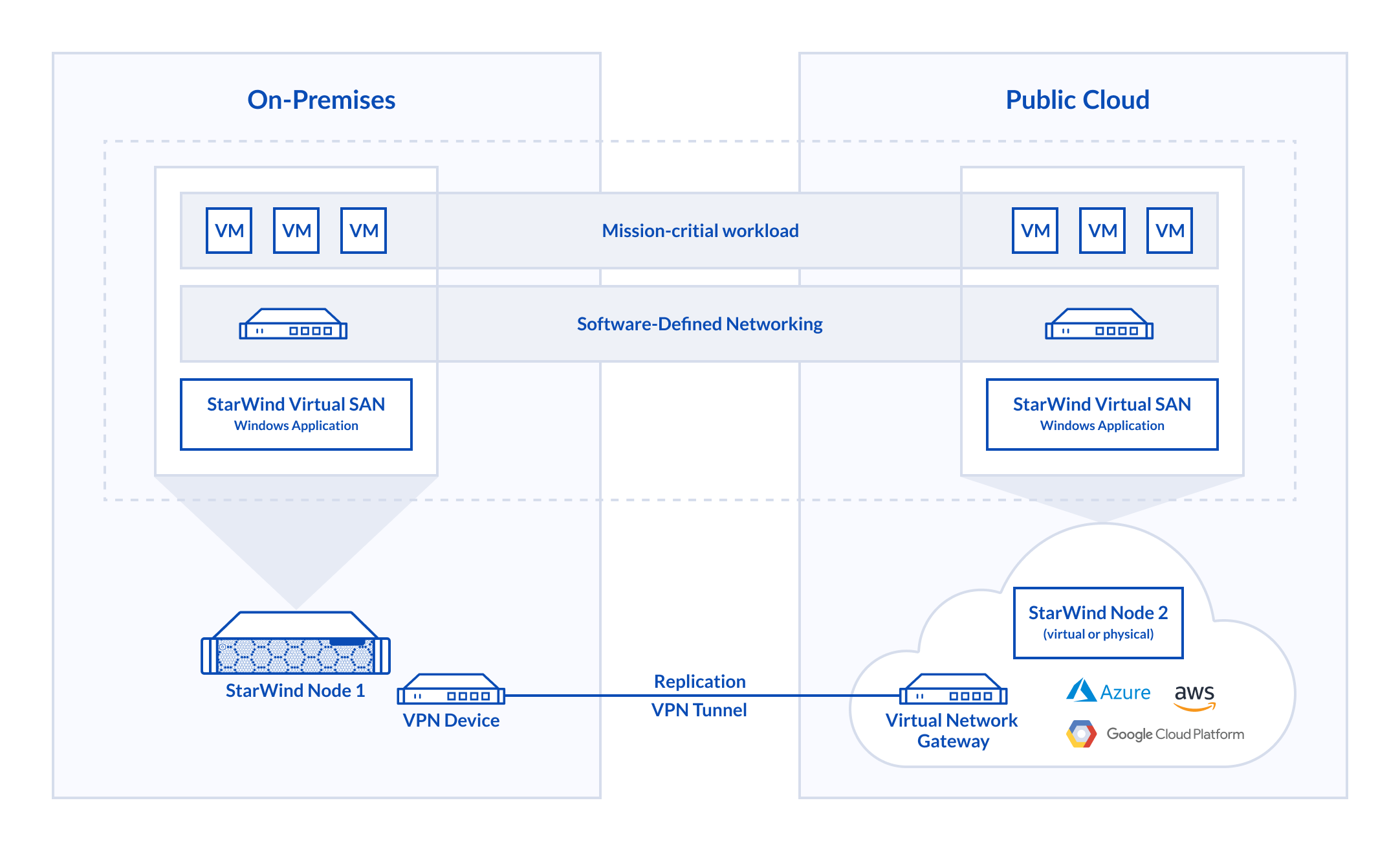
StarWind Virtual SAN for Hyper-V allows building a hybrid cloud solution to extend On-Premises virtualization workloads from a datacenter to Azure public cloud. With its implementation, it becomes possible to assemble the on-premises servers and Azure VMs in a well-known Hyper-V Failover Cluster. The Hybrid Cloud is orchestrated using StarWind Management Console, Hyper-V, and SCVMM, requiring no experience in the Azure platform.
StarWind Virtual SAN for Hyper-V distributes highly-available shared storage replicating the data between locations. Delivering active-active storage, StarWind provides fault-tolerant Disaster Recovery site in Azure public cloud to meet the required RTO and RPO.
Solution Diagram
The diagram below illustrates the StarWind VSAN for Hyper-V Hybrid Cloud configuration with Azure public cloud.
Implementing StarWind Hybrid Cloud with Azure
Prerequisites
Make sure that the following prerequisites are met before deploying StarWind Hybrid Cloud:
- An Azure Subscription (a free trial can be found here)
- Azure location allowing nested virtualization. It’s recommended to choose the location with minimal network latency. The latency can be here
- An externally facing public IPv4 address for a VPN device
- At least 100Mbps network connection to the Internet. The 1Gbps bandwidth link is highly recommended
- Deployed Active Directory structure and DNS at on-premises
- Windows Server 2016 installed on the server that is going to be clustered
Example values
The following values in this document are used as examples. These values can be used to create an environment or referred to better understand the deployment process.
- Virtual Network Name: AzureVNet1
- Azure Address Space: 10.10.0.0/25
- Azure Subnet: 10.10.0.0/26
- Azure GatewaySubnet: 10.10.0.128/27
- Resource Group: AzureRG
- Location: East US
- DNS Server: Optional. The IP address of your DNS server
- Virtual Network Gateway Name: AzureVNet1GW
- Public IP: AzureVNet1GW-IP
- VPN Type: Route-based
- Connection Type: Site-to-site (IPsec)
- Gateway Type: VPN
- Local Network Gateway Name: On-Premise
- Connection Name: AzureVNet1toOnPremise
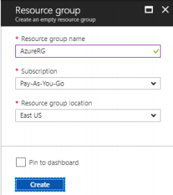
Creating a Resource Group
1. From a browser, navigate to the Azure portal and sign in with an Azure account.
2. Create a Resource group in the Azure portal and click New.
3. In the Search the marketplace field, type ‘Virtual Network’.
4. Locate Resource group from the list and click it to open the Resource group window. Click Create.
Creating a virtual network
1. Navigate to Resource group, select it, and click Add.
2. In the Search the marketplace field, type ‘Virtual Network’.
3. Locate Virtual Network from the list, click it, and open the Virtual Network window.
4. Use Resource Manager as a deployment model.
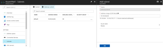
Creating gateway subnet
1. In Resource group, click on the virtual network, open Subnets, and Create a Gateway subnet.
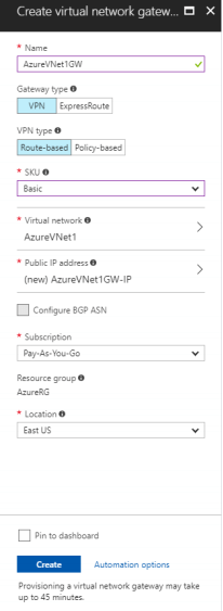
Creating a VPN gateway
1. On the Portal page, click Create new and type ‘Virtual Network Gateway’ in the search field.
2. Locate and click Virtual network gateway.
3. In the Virtual network gateway window, click Create to open Create virtual network gateway.
4. In the Create virtual network gateway window, specify the values for the virtual network gateway:
- Name: Name the gateway.
- Gateway type: Select VPN.
- VPN type: Select the Route-based VPN type.
- SKU: Select the gateway SKU from the drop-down menu.
- Resource Group: click use existing and then select the required group.
- Location: Point to the location where the virtual network is located.
- Virtual network: Choose the virtual network to be added to this gateway.
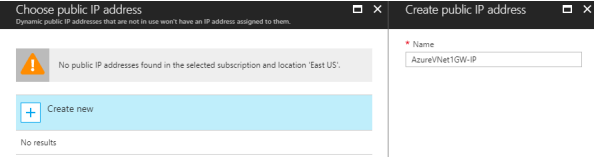
- Public IP address: Click Public IP address and then click Create New in the Choose public IP address window. Input a Name for the public IP address and click OK.
5. Verify the settings.
6. Click Create to begin creating the VPN gateway.
NOTE: The settings will be validated and Deploying Virtual network gateway will appear on the dashboard. Creation of a gateway can take up to 45 minutes.
Creating the local network gateway
1. Provide the site with a name by which Azure can refer to it, and specify the IP address of the on-premises VPN device to which a connection will be established.
2. Specify the IP address prefixes that will be routed through the VPN gateway to the VPN device. The specified address prefixes are the prefixes located on the on-premises network.
3. Navigate to All resources, click +Add.
4. In the Search box, locate and select Local network gateway. Then click Create to open the Create local network gateway window.
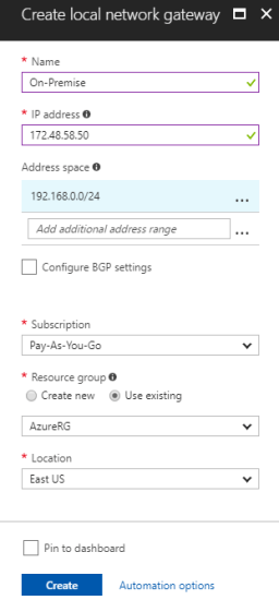
5. On the Create local network gateway blade, specify the values for the local network gateway:
- Name: The name of the local network gateway object
- IP address: The public IP address of the VPN device connected to Azure
- Address Space: The address ranges for the network that the local network represents
- Subscription: Subscription plan
- Resource Group: The resource group that can be used
- Location: The location where the object will be created
6. Click Create at the bottom of the window to deploy the local network gateway.
Creating the VPN connection
1. To create the Site-to-Site VPN connection between the virtual network gateway and on-premises VPN device, open the Virtual network gateway window.
2. On the AzureVNet1GW window, click Connections.
3. At the top of the Connections window, click +Add to open Add connection.
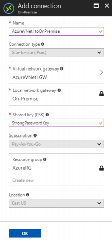
4. On the Add connection window, fill in the values to create the connection:
- Name: Name the connection. In this guide, the AzureVNet1toOnPremise name is used.
- Connection type: Select Site-to-site (IPSec).
- Virtual network gateway: This value is fixed because of the connection from this gateway.
- Local network gateway: Click Choose a local network gateway and select the local network gateway to be used. In this guide, On-Premise is used.
- Shared Key: This value must match the value used for the local on-premises VPN device. In this guide, ‘StrongPasswordKey’ is used.
5. Click OK to create your connection.
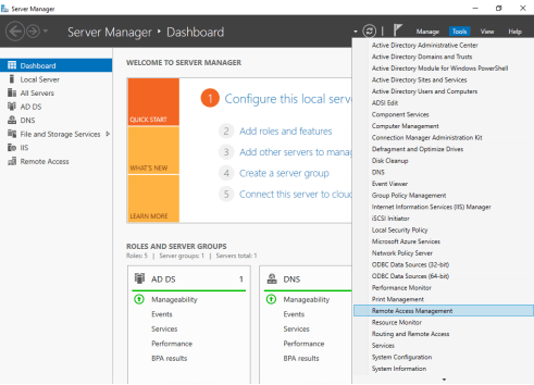
Setting Up RRAS Server
NOTE: In order to set up the VPN tunnel between on-premises and Azure, the Routing and Remote Access Service (RRAS) role is configured on Windows Server 2016, which in this guide also stands for AD DC and DNS roles. In case of using an external VPN device, check its compatibility with Azure here.
1. Open Server Manager and select Manage -> Add Roles and Features.
2. In the Add Roles and Features Wizard -> Before You Begin, click Next.
3. In Installation Type, select Role-based, and click Next.
4. In Server Selection, select RRAS-Server and click Next.
5. In Server Roles, check Remote Access and click Next.
6. On the Features and Remote Acess steps, click Next.
7. On the Role Services step, choose Direct Access and VPN (RAS), Routing and click Add Features on the pop-up window. Click Next.
8. On the Web Server Role (IIS) step, click Next.
9. On the Role Services step, accept the defaults and click Next.
10. In Confirmation, click Install.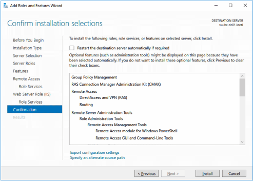
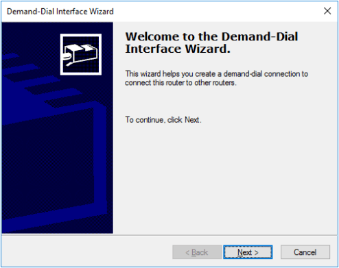
Configuring the RRAS Server
1. Open Routing and Remote Access and select Secure connection between two private networks. Complete the configuration with the default settings.
2. In Demand-Dial Interface Wizard, specify a name for the Interface. In this guide, “OnPremise-To-Azure” is used.
3. In Connection Type, select Connect using virtual private networking (VPN).
4. In VPN Type, select IKEv2.
5. In Destination Address, enter Host name or IP address.
6. In Protocols and Security, select Route IP packets on this interface.
7. In Static Routes for Remote Networks, add the route of the Azure-VMs subnet.
8. On the Dial-Out Credentials step, enter the credentials.
9. Click Finish to complete the wizard.
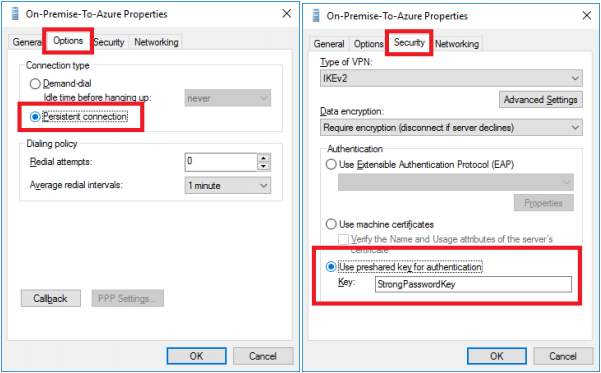
10. In Routing and Remote Access > Network Interfaces, right-click On-Premise-To-Azure and choose Properties.
11. Click the Options tab and set the connection type to persistent. In the Security tab, set the pre-shared key set up on Azure previously.
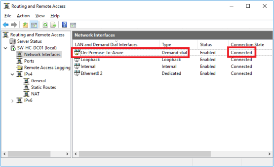
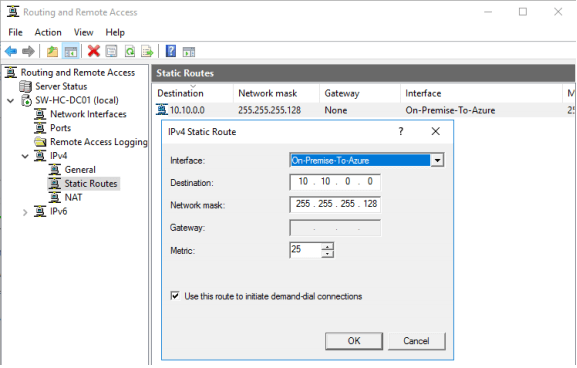
12. Right-click the On-Premise-To-Azure connection and select Connect. It will be displayed as connected in RRAS as shown in the screenshot below.
13. Double check IPv4 Static Routes. The configuration should look the same as in the screenshot below.
Opening Ports in the Firewall
1. Open Windows Firewall, click the Exceptions tab and then click Add Port.
2. Click Inbound Rules and click New Rule.
3. Allow connection for 500, 4500, 1701, 50 UPD ports to allow VPN traffic to pass through.
4. Repeat the same procedure for Outbound Rules.
Preconfiguring the On-Premise server
NOTE: This document assumes that the domain controller is set up and the On-Premise server is added to the domain. The Failover Clustering and Multipath I/O features, and the Hyper-V role must be installed on the local server. These actions can be performed using Server Manager (the Add Roles and Features menu item).
1. Download and install StarWind Virtual SAN on the local server. The latest StarWind build can be found by following this link.
Enabling Multipath Support
1. Open the MPIO manager: Start->Administrative Tools->MPIO.
2. Navigate to the Discover Multi-Paths tab.
3. Select the Add support for iSCSI devices checkbox.
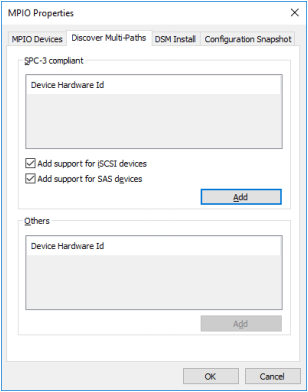
4. Click Add. Then click Yes when prompted to restart the server.
Deploying StarWind VM in Azure
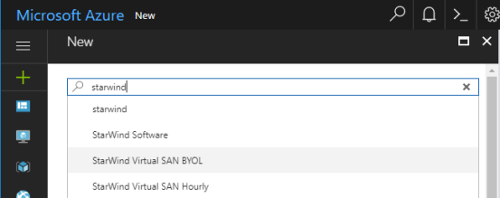
1. Navigate to the Azure portal and search for StarWind Virtual SAN VM.
2. Select StarWind Virtual SAN BYOL in case the StarWind license is already purchased.
NOTE: Alternatively, select StarWind Virtual SAN Hourly. Alike BYOL, it’s a pre-installed Azure VM with the Hyper-V role, MPIO, and Failover Cluster features but StarWind is shipped on a per-hour license basis.
3. Create a StarWind VM using Resource Manager.
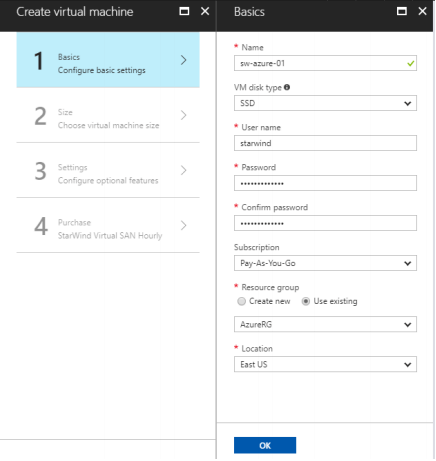
4. Enter Name for the virtual machine.
5. Enter User name and a strong Password to create a local account on the VM.
6. Select the existing Resource group or type a name for a new one. In the example, AzureRG is the name of the resource group.
7. Select an Azure datacenter Location to run the VM. In this guide, East US is specified as the location.
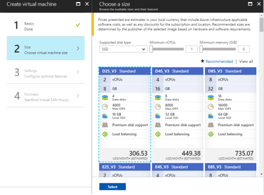
NOTE: The Size windows identifies the configuration details of the VM, and lists various choices that include OS, number of processors, disk storage type, and estimated monthly usage costs. For the StarWind Hybrid Cloud implementation, only Dv3 and Ev3 VM sizes are supported.
8. Choose the VM size, and then click Select to continue. In this example, D2S_V3 Standard is specified as a VM size.
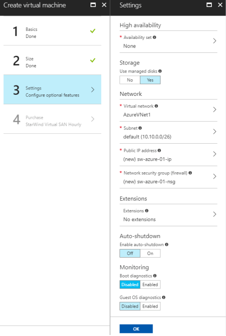
9. In the Settings window, click Network security group.
10. Add 500, 4500, 1701, 50 UPN ports to an inbound and an outbound rule to allow VPN traffic to pass through.
11. Mark the High availability option as None.
12. In the Summary window, double check the settings specified in the previous steps and click OK.
Adding a network adapter
NOTE: While it’s possible to create NICs in the Azure management portal, they can not be attached to VMs there. That can only be done using PowerShell. Make sure the latest version of Microsoft Azure PowerShell is installed on the PC. The latest release can be installed using the Web Platform Installer.
1. Open Windows PowerShell ISE and log in to your Azure subscription using the following cmdlet:
Login-AzureRmAccount
2. Define the following variables for the VM, network, and other parameters that will be required:
$vmName = ‘sw-sed-azure-01’
$vnetName = ‘AzureVNet1’
$RG = ‘AzureRG’
$subnetName = ‘default’
$nicName = ‘sw-sed-azure-01011’
$location = ‘East US
$ipAddress = ’10.10.0.10’
3. Create an object for the VM using Get-AzureRmVM:
$VM = Get-AzureRmVM -Name $vmName -ResourceGroupName $RG
4. Create an object for the virtual network using Get-AzureRmVirtualNetwork:
$vnet = Get-AzureRmVirtualNetwork -Name $vnetName -ResourceGroupName $RG
5. Prior to connecting a NIC to a subnet ($subnetName), receive the subnet ID in PowerShell:
$subnetID = (Get-AzureRmVirtualNetworkSubnetConfig -Name $subnetName -VirtualNetwork $vnet).Id
6. Create a new NIC using the New-AzureRmNetworkInterface cmdlet:
New-AzureRmNetworkInterface -Name $nicName -ResourceGroupName $RG -Location $location -SubnetId $subnetID -PrivateIpAddress $ipAddress
7. The new NIC can now be attached to the VM. Create an object for the NIC using the Get-AzureRmNetworkInterface cmdlet:
$NIC = Get-AzureRmNetworkInterface -Name $nicName -ResourceGroupName $RG
8. Add the NIC to the VM configuration:
$VM = Add-AzureRmVMNetworkInterface -VM $VM -Id $NIC.Id
9. To check that the configuration has been changed to include the new NIC, run the command below to see the list of NICs attached to the VM:
$VM.NetworkProfile.NetworkInterfaces
10. Assign the first NIC as the primary:
$VM.NetworkProfile.NetworkInterfaces.Item(0).Primary = $true
11. Commit the new configuration using the Update-AzureRmVM cmdlet:
Update-AzureRmVM -VM $VM -ResourceGroupName $RG
IP forwarding
1. Navigate to VM -> Networking.
2. Select the first Network interface.
3. Open IP configuration page from the sidebar menu
4. Enable IP forwarding settings and Save the configuration.
Adding storage
NOTE: Azure requires a Storage account to store VM disks.
1. On the Hub menu, select New -> Storage -> Storage account.
2. Enter a name for the storage account.
3. Specify the deployment model to be used: Resource Manager or Classic. Resource Manager is the recommended deployment model.
4. Select General purpose as the type of storage account and specify the performance tier: Standard or Premium with regards to On-Premises storage configuration. The default is Standard.
5. Select the replication option, subscription, and region.
6. Click Create to create the storage account.
7. Navigate to StarWind VM -> Disks.
8. Click +Add data disk.
9. Specify disk Account type and Size according to On-Premises storage configuration.
10. Select Storage container.
11. Click OK to finish the setup.
Install roles and Features
1. Connect to VM using Remote Desktop Connection.
2. Launch Server Manager and click Add New Roles and Features.
3. Check the Hyper-V role installation.
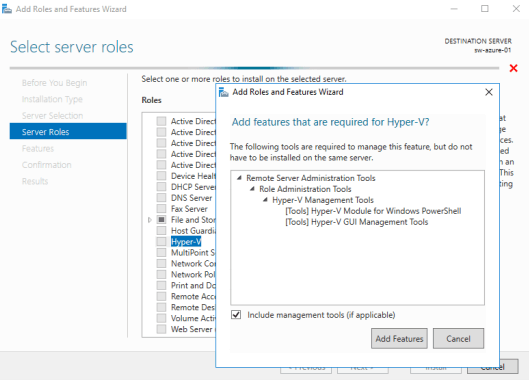
4. Select Failover Clustering and Multipath I/O features installation.
5. Complete the installation on Azure VM.
Join the Azure VM to the on-premises domain
1. Press Windows key + X in Azure VM to invoke the context menu, and select System field.
2. In the opened window, click Change settings to open System properties.
3. Click the Change.. button. Mark the domain field and type the local domain name.
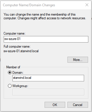
4. Click the OK button. Confirm the action by entering the domain administrator’s credentials.
5. Accept system reboot to complete the join.
Configuring StarWind Highly-Available Storage
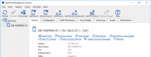
1. Double-click the StarWind tray icon to launch StarWind Management Console.
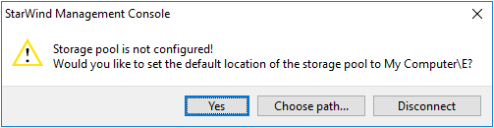
2. Press the Yes button to configure the storage pool. To change the storage pool destination, press Choose path… and point the browser to the necessary disk.
NOTE: Please make sure that each of the arrays, which will be used by StarWind Virtual SAN to store virtual disk images meets the following requirements:
- Initialized as GPT
- Have a single NTFS-formatted partition
- Have a drive letter assigned
3. Press the Add Device (advanced) button on the toolbar.
4. Add Device Wizard will appear. Select Hard disk device and click Next.
5. Select Virtual disk and click Next.
6. Specify the virtual disk Name, Location, and Size. Click Next

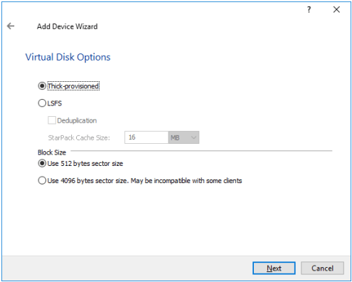
7. Specify Virtual Disk Options. Click Next
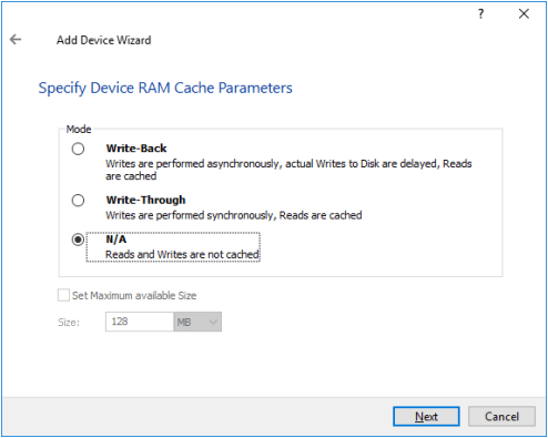
8. Define the caching policy and specify the cache size (in MB). Click Next
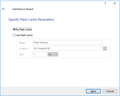
9. Define the Flash Cache Parameters policy and size if necessary. Click Next to continue
NOTE: It is highly recommended to use SSD-based storage for “Flash Cache” caching.
10. Specify the target parameters.
11. Select the Target Name checkbox to enter a custom name of a target. Otherwise, the name will be generated automatically based on the target alias. Click Next to continue.
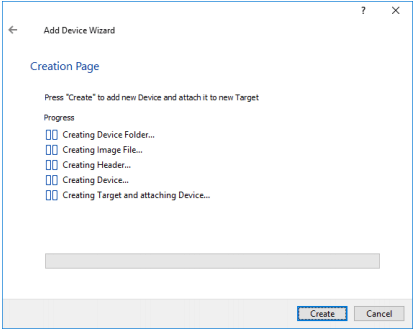
12. Click Create to add a new device and attach it to the target. Then, click Close to close the wizard.
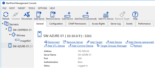
13. Right-click on the servers field and select Add Server. Select the Azure VM as a new StarWind Server to add. Click OK to continue.
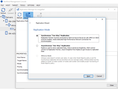
14. Right-click on the created device and select Replication Manager. Press the Add Replica button in the Replication Manager window.
15. Select Synchronous “Two-Way Replication” and click Next to proceed.
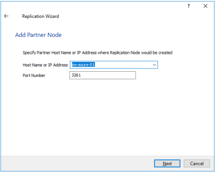
16. Specify the partner server Host Name or IP address. The default StarWind management port is 3261. In case a different port is configured, please type it in the Port number field. Click Next.
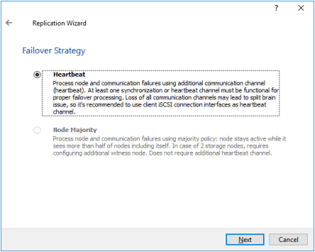
17. Select the Heartbeat Failover Strategy.
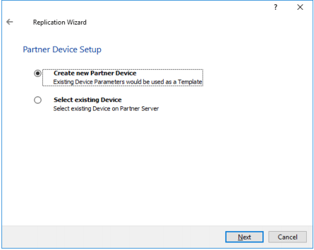
18. Choose Create new Partner Device.
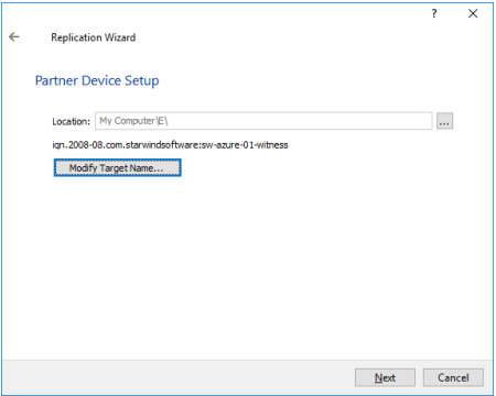
19. Specify the partner device Location if necessary. The target name can be modified by clicking the appropriate button.
20. To select the synchronization and heartbeat channels for the HA device, click Change network settings. To modify the ALUA settings, click the appropriate button.
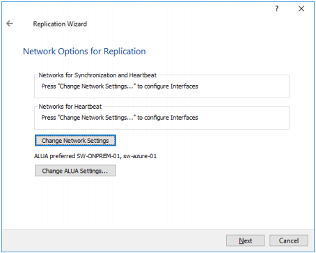
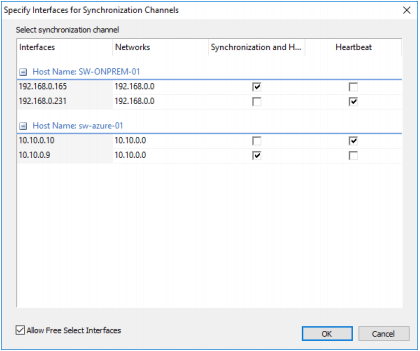
21. Click Allow Free Select Interfaces to be able to specify NICs from different subnetworks. Specify the interfaces for synchronization and Heartbeat. Click OK. Then click Next.
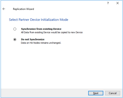
22. Set Do not Synchronize as the partner device initialization mode. Click Next.
NOTE: Use this type of synchronization for adding partner only to the device which doesn’ contain any data.
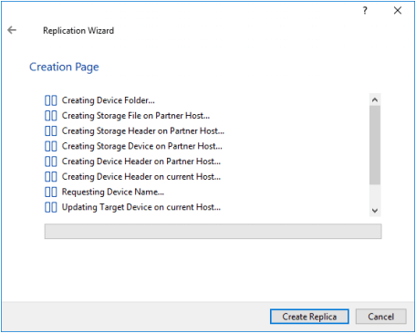
23. Press the Create Replica button. Then click Close.
24. The added device will appear in StarWind Management Console.
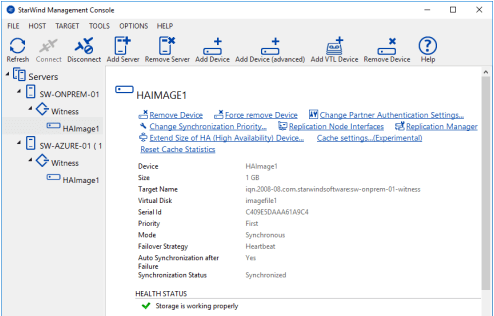
25. Repeat the steps 1 – 23 for the remaining virtual disks that will be used for File Share.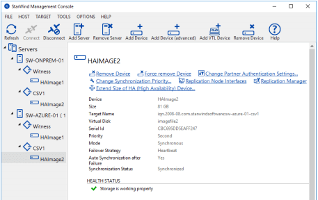
Configuring Failover Cluster
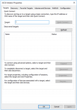
1. To launch Microsoft iSCSI Initiator, click Start > Administrative Tools > iSCSI Initiator or iscsicpl from the command line interface. The iSCSI Initiator Properties window appears.
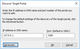
2. Navigate to the Discovery tab.
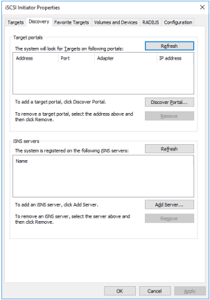
3. Click the Discover Portal button. Discover Target Portal dialog appears. Type in 127.0.0.1.
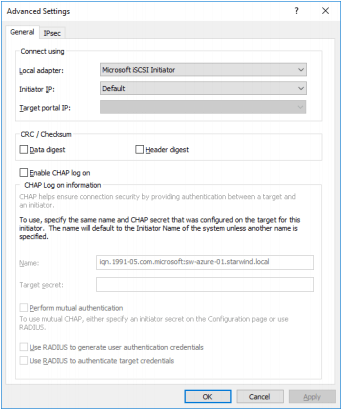
4. Click the Advanced button. Select Microsoft ISCSI Initiator as Local adapter and select Initiator IP (leave the default for 127.0.0.1).
5. Click OK. Then click OK again to complete the Target Portal discovery.
6. Click the Discover Portal… button again.
7. Discover Target Portal dialog appears.

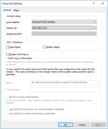
8. Type in the first IP address of the partner node used to connect the secondary mirrors of the HA devices. Click Advanced.
9. Select Microsoft ISCSI Initiator as Local adapter and select the Initiator IP in the same subnet as the IP address on the partner server from the previous step.
10. Click OK. Then click OK again to complete the Target Portal discovery.
11. Click the Discover Portal… button again
12. Discover Target Portal dialog appears. Type in the IP address of the partner node used to connect the parent node of the HA devices.
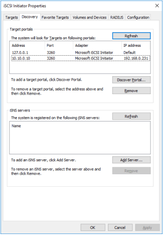
13. Click Advanced.
14. All target portals have been added to the first node.
15. Complete the steps 1-14 for the second node.
16. All target portals have been added to the second node.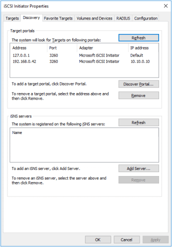
Connecting Targets
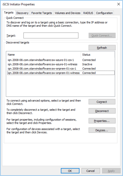
1. Click the Targets tab. The previously created targets are listed in the Discovered Targets section.
NOTE: If the created targets are not listed, check the firewall settings of the StarWind Server as well as the list of networks served by the StarWind Server (navigate to StarWind Management Console -> Configuration -> Network).
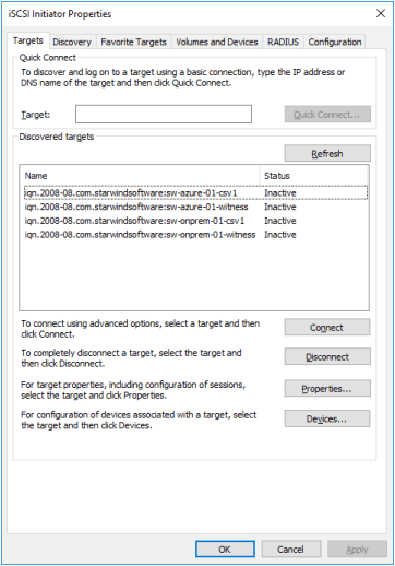
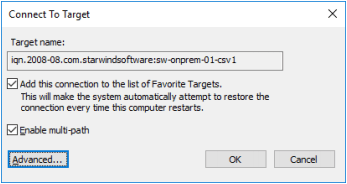
2. Select a target of the witness located on the local server and click Connect. Then click Advanced.
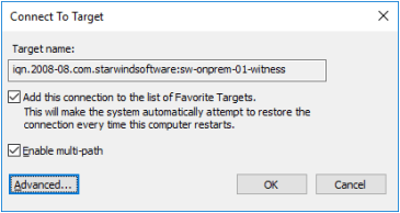
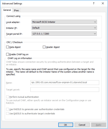
3. Select Microsoft iSCSI Initiator in the Local adapter text field.
4. Select 127.0.0.1 in the Target portal IP.
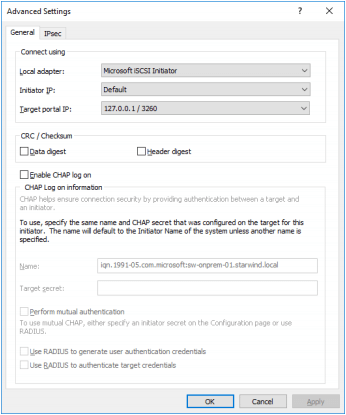
5. Click OK. Then click OK again.
NOTE: Do not connect the partner-target for the Witness device from the other StarWind node.
4. Select another target located on the local server and click Connect. Click Advanced.
5. Select Microsoft iSCSI Initiator in the Local adapter text field. Select 127.0.0.1 in the Target portal IP.
6. Click OK. Then click OK again.
7. Select the partner-target from the other StarWind node and click Connect. Click Advanced.
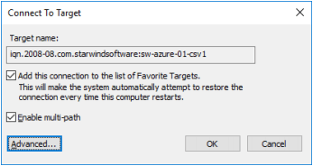
8. Select Microsoft iSCSI Initiator in the Local adapter text field.
9. In the Initiator IP field, select the IP address for the ISCSI channel.
10. In the Target portal IP, select the corresponding portal IP from the same subnet.
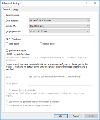
11. Click OK. Then click OK again.
12. Repeat the steps 1-11 on the local StarWind node for all HA devices.
13. Repeat the steps 1-12 on the StarWind node in Azure, specifying corresponding local and data channel IP addresses. 
Multipath Configuration
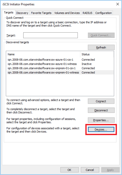
1. Configure the MPIO policy for each device and specify the localhost (127.0.0.1) as the active path. Select a target located on the local server and click Devices.
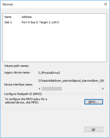
2. The Devices dialog appears. Click MPIO.
3. Select Fail Over Only as Load balance policy and then set the local path as active.
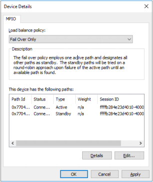
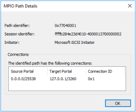
4. Verify that 127.0.0.1 is the active path by selecting it from the list and by clicking Details.
5. Repeat the steps 1-4 on the second node.
6. Initialize the disks and create partitions on them using the Computer Management snap-in. Make sure that the disk devices are visible on both nodes.
NOTE: It is recommended to initialize the disks as GPT.
Creating Failover Cluster
1. Open Server Manager and select the Failover Cluster Manager item from the Tools menu.
2. Click the Create Cluster link in the Actions section of the Failover Cluster Manager.
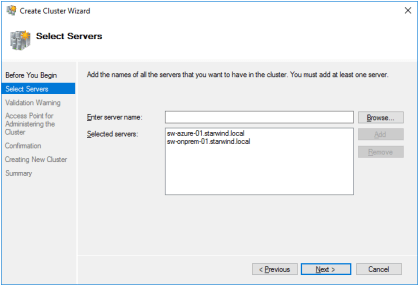
3. Specify the servers to be added to the cluster.
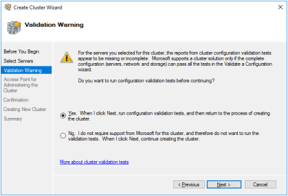
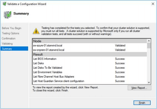
4. Validate the configuration by passing the cluster validation tests.
5. Once the validation is completed, click Finish.
6. Specify Cluster Name and IP addresses for two subnets: On-Premises and Azure networks.
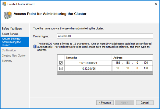
7. Make sure that all the settings are correct. Click the Previous button to make any changes.

NOTE: If the checkbox “Add all eligible storage to the cluster” is selected, the wizard will try to add all StarWind devices to the cluster automatically. The smallest device will be assigned as a Witness.
8. After the cluster creation process has been completed, the system displays a report with a detailed information.
9. Click Finish to close the wizard.
Adding Cluster Shared Volumes
1. Open Failover Cluster Manager.
2. Navigate to Cluster->Storage -> Disks.
3. Click Add Disk in the Actions panel, choose StarWind disks from the list, and click OK.
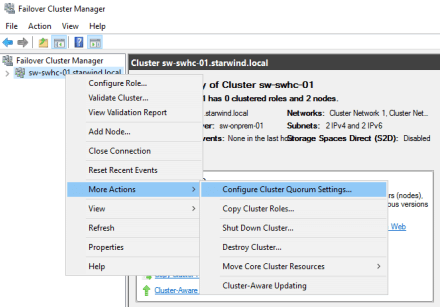
4. To configure a Witness drive, right-click Cluster->More Actions->Configure Cluster Quorum Settings, follow the wizard, and use the default quorum configuration.
NOTE: To avoid an unnecessary CSV overhead, configure each CSV to be owned by one cluster node. This node should also be the preferred owner of the VMs running on that node.
5. Right-click the required disk and select Add to Cluster Shared Volumes.

Once the disks are added to the cluster shared volumes list, you can start creating highly available virtual machines on them.
NOTE: To avoid the unnecessary CSV overhead, configure each CSV to be owned by one cluster node. This node should also be the preferred owner of the VMs running on that node.
6. Check the Server Name Dependencies. For two different subnets, the OR dependency type must be configured for the failover between locations.

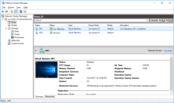
Testing Failover
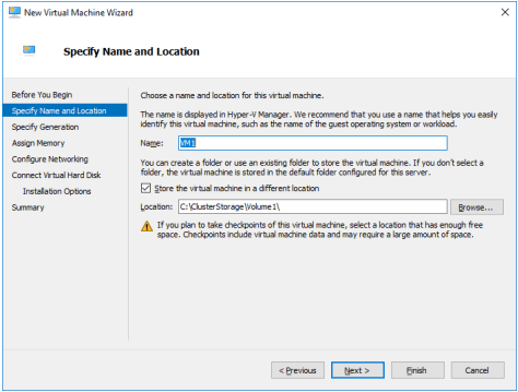
1. Create a VM(s) on a cluster node. Use CSV to host the VM(s).
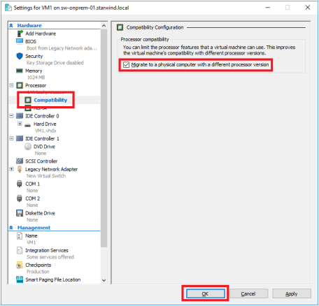
2. Open the VM settings to enable Live Migration between nodes with different processor versions.
3. Install the OS on the VM.
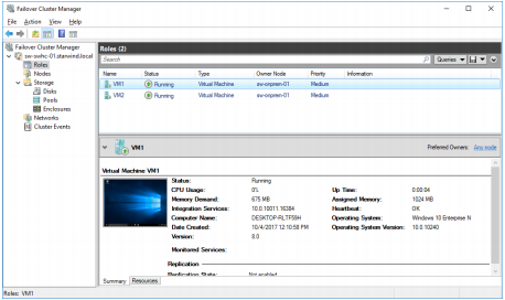
4. Perform Live Migration and VM failover between On-Premises and Azure nodes.
Conclusion
By following the steps and recommendations presented in this document, IT professionals can leverage the benefits of combining on-premises and cloud resources while ensuring data availability and disaster recovery capabilities. This hybrid cloud setup offers flexibility and scalability for various virtualization workloads, contributing to a robust and efficient IT infrastructure.
