

StarWind Virtual SAN:
Configuration Guide for Red Hat Virtualization [KVM], StarWind Deployed as a Controller VM using Web UI
- August 15, 2022
- 30 min read
- Download as PDF
Annotation
Relevant Products
StarWind Virtual SAN (VSAN)
Purpose
This guide offers a detailed steps for deploying and configuring StarWind Virtual SAN® Controller Virtual Machine (CVM) within the Red Hat Virtualization [KVM] environment and creating StarWind devices using the Web UI. It includes links to the system requirements, RAID settings, best practices, and steps to ensure a seamless and efficient setup.
Audience
Created for IT specialists, system administrators, and professionals familiar with Red Hat Virtualization [KVM], this guide is intended to help with deploying and configuring StarWind Virtual SAN CVM with RHV.
Expected Result
Upon completing this guide, users will have a comprehensive understanding of the deployment and configuration process of StarWind Virtual SAN CVM within the Red Hat Virtualization [KVM] environment. They will be adept in ensuring the system is set up in alignment with best practices, achieving optimal performance and reliability.
StarWind VSAN System Requirements
Prior to installing StarWind Virtual SAN, please make sure that the system meets the requirements, which are available via the following link:
https://www.starwindsoftware.com/system-requirements
Recommended RAID settings for HDD and SSD disks:
https://knowledgebase.starwindsoftware.com/guidance/recommended-raid-settings-for-hdd-and-ssd-disks/
Please read StarWind Virtual SAN Best Practices document for additional information:
https://www.starwindsoftware.com/resource-library/starwind-virtual-san-best-practices
Pre-configuring the KVM Hosts
The diagram below illustrates the network and storage configuration of the solution:

1. Make sure that a oVirt engine is installed on a separate host.
2. Deploy oVirt on each server and add them to oVirt engine.
3. Define at least 2x network interfaces on each node that will be used for the Synchronization and iSCSI/StarWind heartbeat traffic. Do not use ISCSI/Heartbeat and Synchronization channels
over the same physical link. Synchronization and iSCSI/Heartbeat links can be connected either via redundant switches or directly between the nodes (see diagram above).
4. Separate Logical Networks should be created for iSCSI and Synchronization traffic based on the selected before iSCSI and Synchronization interfaces. Using oVirt engine Netowrking page create two Logical Networks: one for the iSCSI/StarWind Heartbeat channel (iSCSI) and another one for the Synchronization channel (Sync).
5. Add physical NIC to Logical network on each host and configure static IP addresses. In this document, the 172.16.10.x subnet is used for iSCSI/StarWind heartbeat traffic, while 172.16.20.x subnet is used for the Synchronization traffic.
NOTE: In case NIC supports SR-IOV, enable it for the best performance. Contact support for additional details.
Enabling Multipath Support
8. Connect to server via ssh.
9. Create file /etc/multipath/conf.d/starwind.conf with the following content:
devices{
	device{
		vendor "STARWIND"
		product "STARWIND*"
		path_grouping_policy multibus
		path_checker "tur"
		failback immediate
		path_selector "round-robin 0"
		rr_min_io 3
		rr_weight uniform
		hardware_handler "1 alua"
	}
}
10. Restart multipathd service.
systemctl restart multipathd
11. Repeat the same procedure on the other server.
Creating NFS share
1. Make sure that each host has free storage to create NFS share.
2. Enable nfs server and rpcbind services.
systemctl enable --now nfs-server rpcbind
3. Create directory for NFS share.
mkdir -p /mnt/nfs
4. Change rights and owner of the share to KVM
chmod 0775 /mnt/nfs/
chown -R nobody:users /mnt/nfs/
5. Add NFS share to /etc/exports file.
vi /etc/exports
/mnt/nfs/ *(rw,anonuid=36,anongid=36)
6. Restart NFS server service.
systemctl restart nfs-server
7. Check that share has been exported.
exportfs -rvv
8. Add firewall rules for NFS.
firewall-cmd --add-service={nfs,nfs3,rpc-bind} --permanent
firewall-cmd --reload
Deploying Starwind Virtual SAN CVM
1. Download StarWind VSAN CVM KVM: VSAN by StarWind: Overview
2. Extract the VM StarWindCVM.ova file from the downloaded archive.
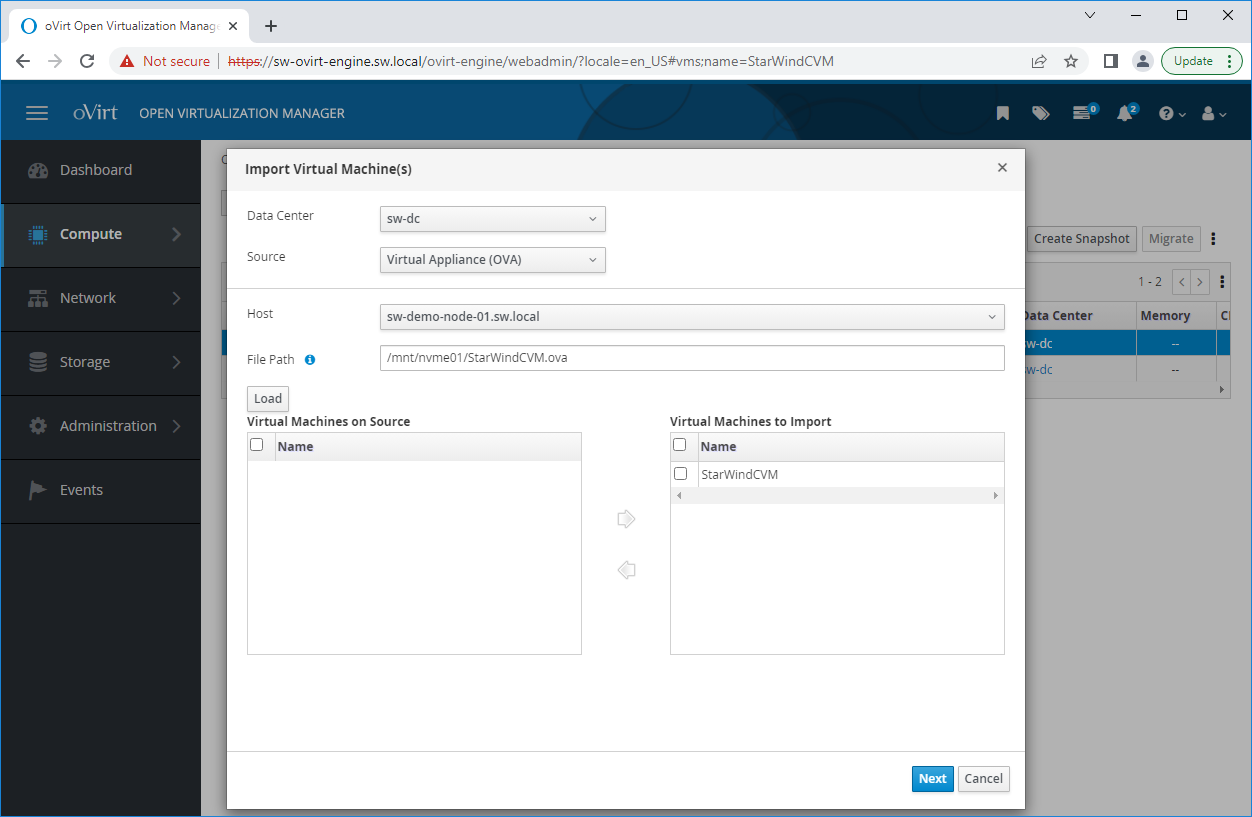
3. Upload StarWindCVM.ova file to the oVirt Host via any SFTP client.
4. Change owner of the StarWindCVM.ova.
chown -R nobody:users /mnt/nfs/
5. Login to oVirt and open Compute -> Virtual Machines page. Choose Import.
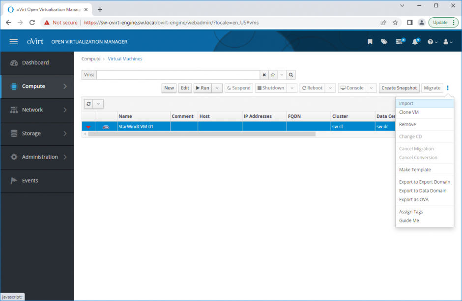
6. Specify path to .ova file and choose VM to import. Click Next.
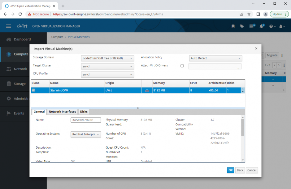
7. Verify VM settings and configure networks. Click OK.
8. Repeat all the steps from this section on other oVirt hosts.
Initial Configuration Wizard
1. Start the StarWind Virtual SAN Controller Virtual Machine.
2. Launch the VM console to view the VM boot process and obtain the IPv4 address of the Management network interface.
NOTE: If the VM does not acquire an IPv4 address from a DHCP server, use the Text-based User Interface (TUI) to set up the Management network manually.
Default credentials for TUI: user/rds123RDS
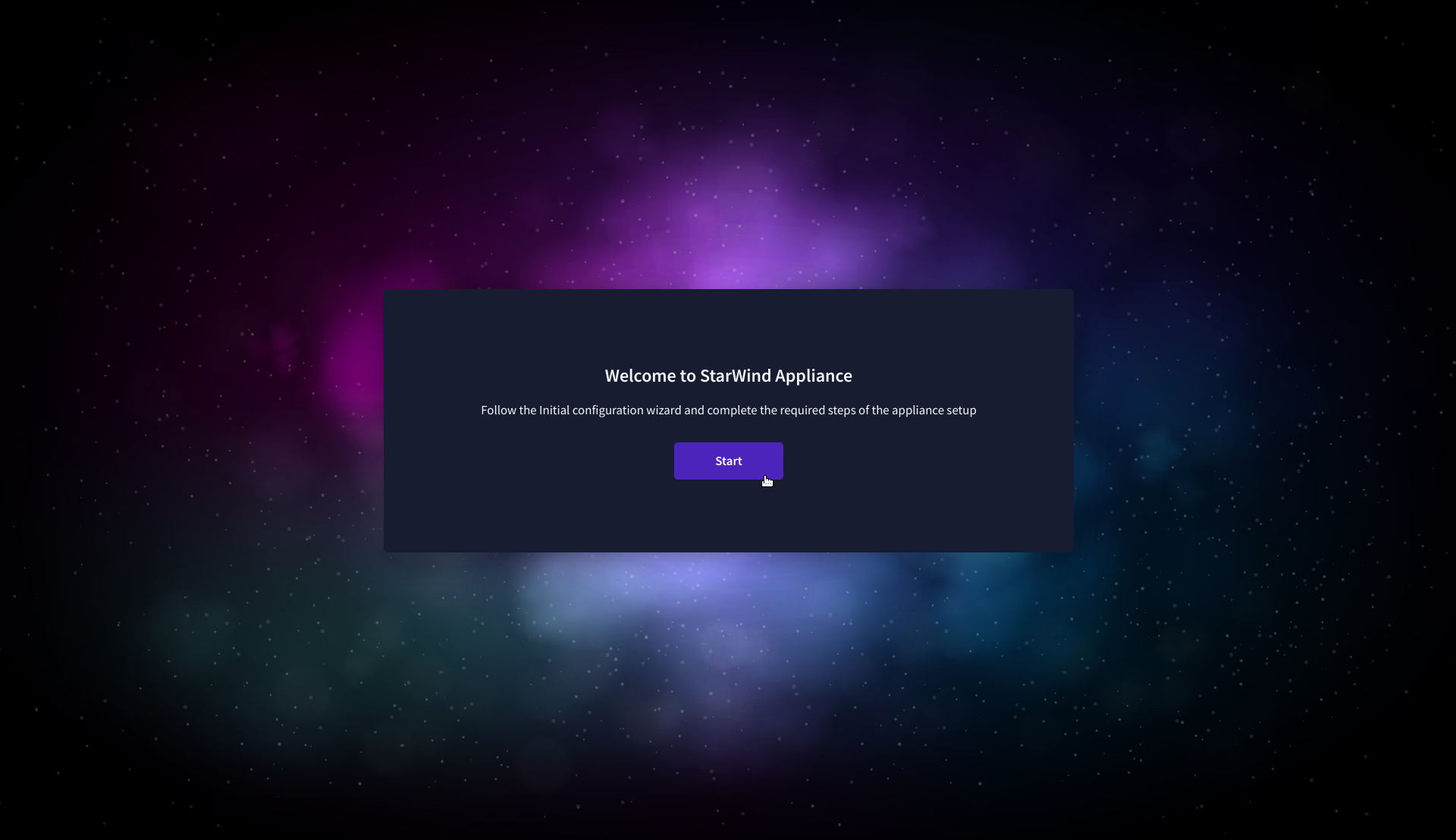
3. Using a web browser, open a new tab and enter the VM’s IPv4 address to access the StarWind VSAN Web Interface. On the Your connection is not private screen, click Advanced and then select Continue to…

4. On the Welcome to StarWind Appliance screen, click Start to launch the Initial Configuration Wizard.
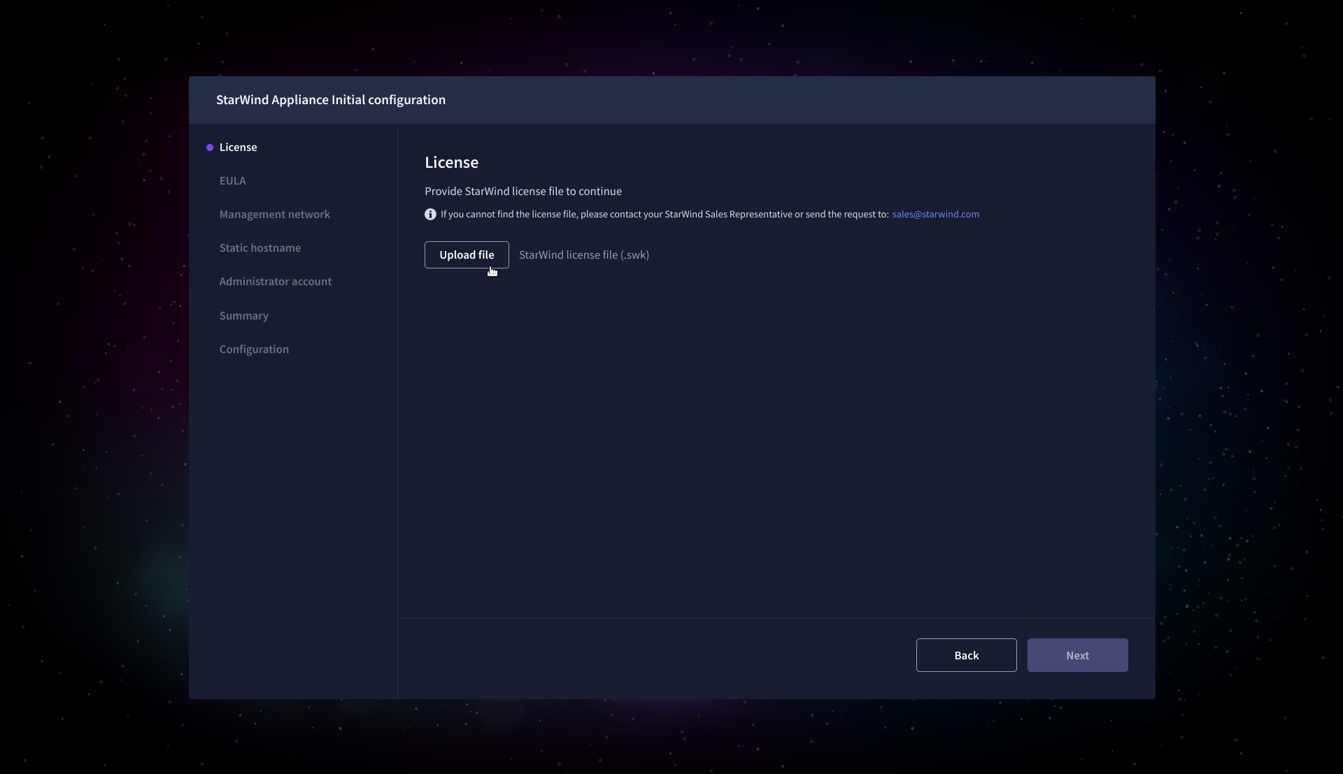
5. On the License step, upload the StarWind Virtual SAN license file.
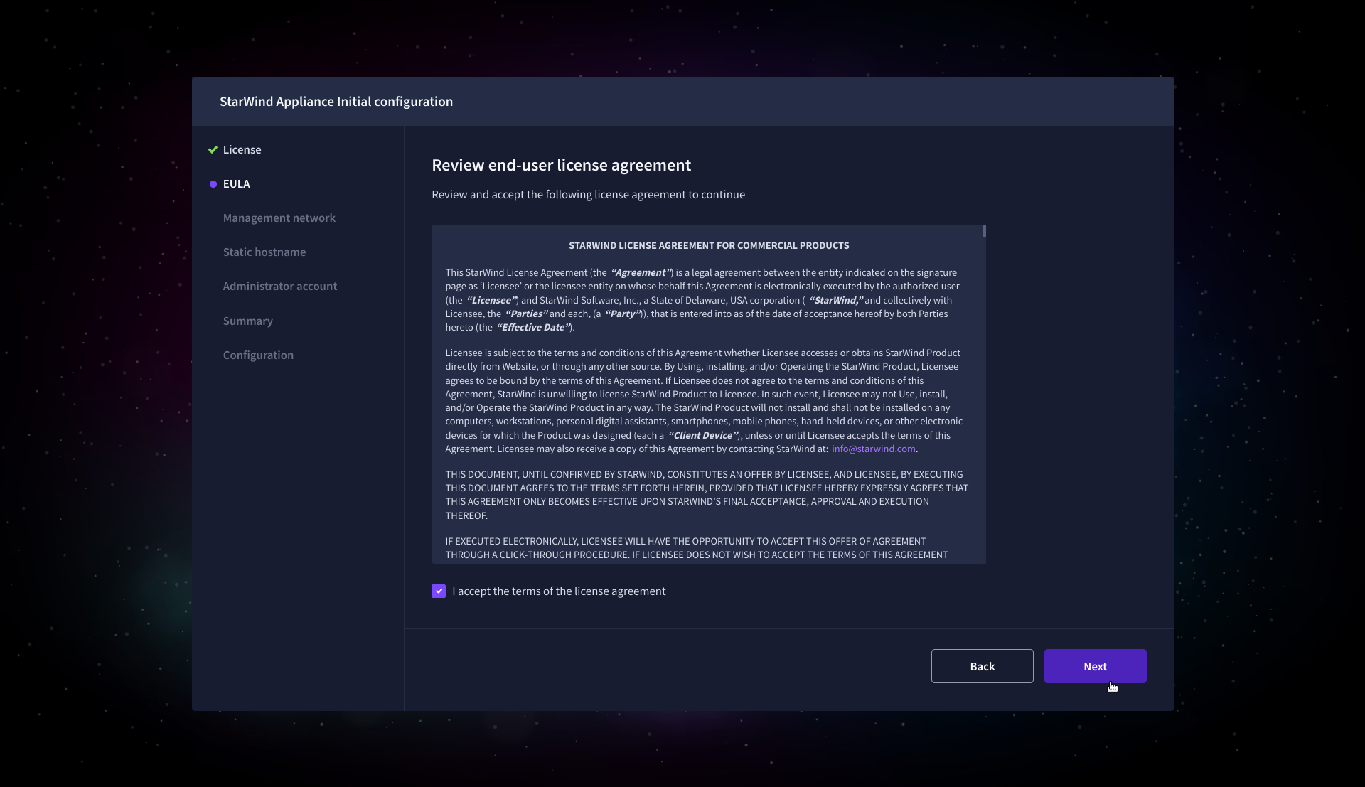
6. On the EULA step, read and accept the End User License Agreement to continue.
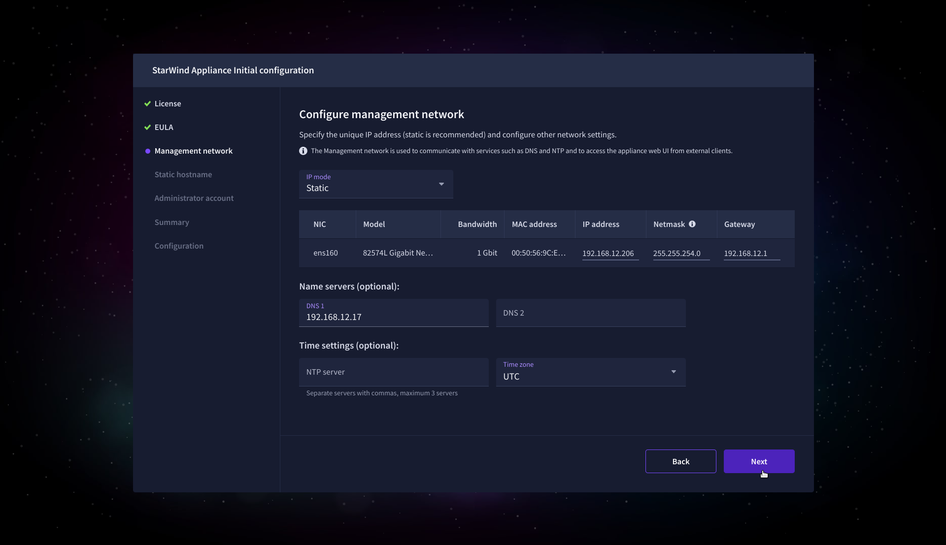
7. On the Management network step, review or edit the network settings and click Next.
IMPORTANT: The use of Static IP mode is highly recommended.
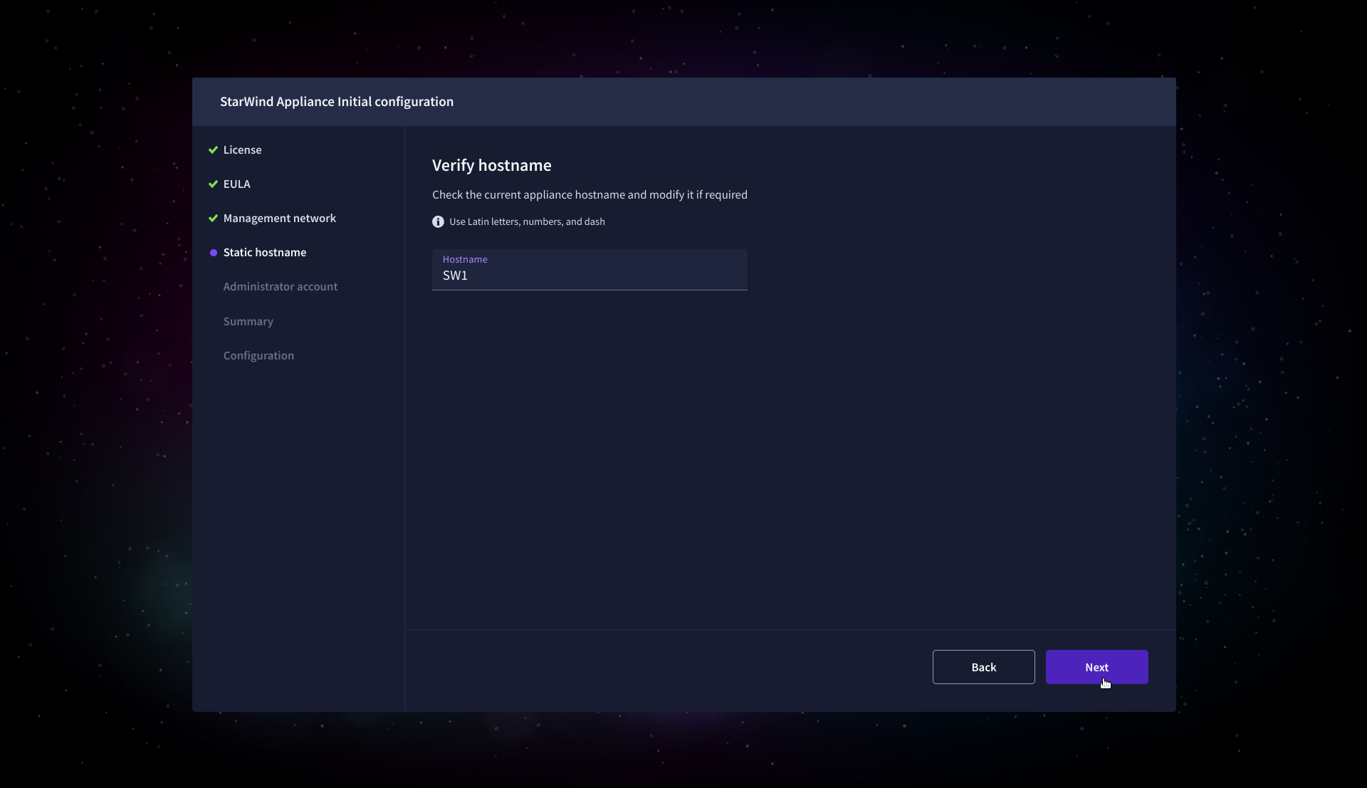
8. On the Static hostname, specify the hostname for the virtual machine and click Next.
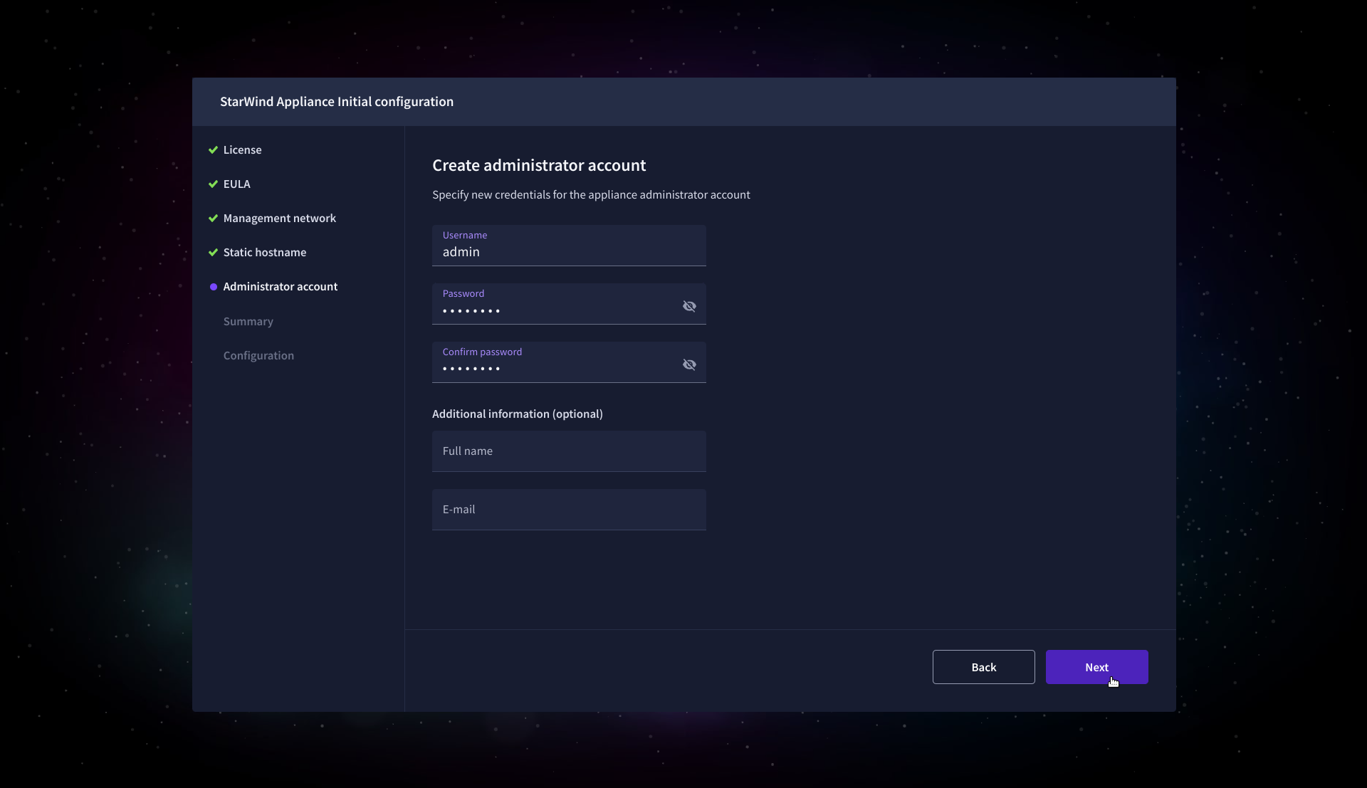
9. On the Administrator account step, specify the credentials for the new StarWind Virtual SAN administrator account and click Next.
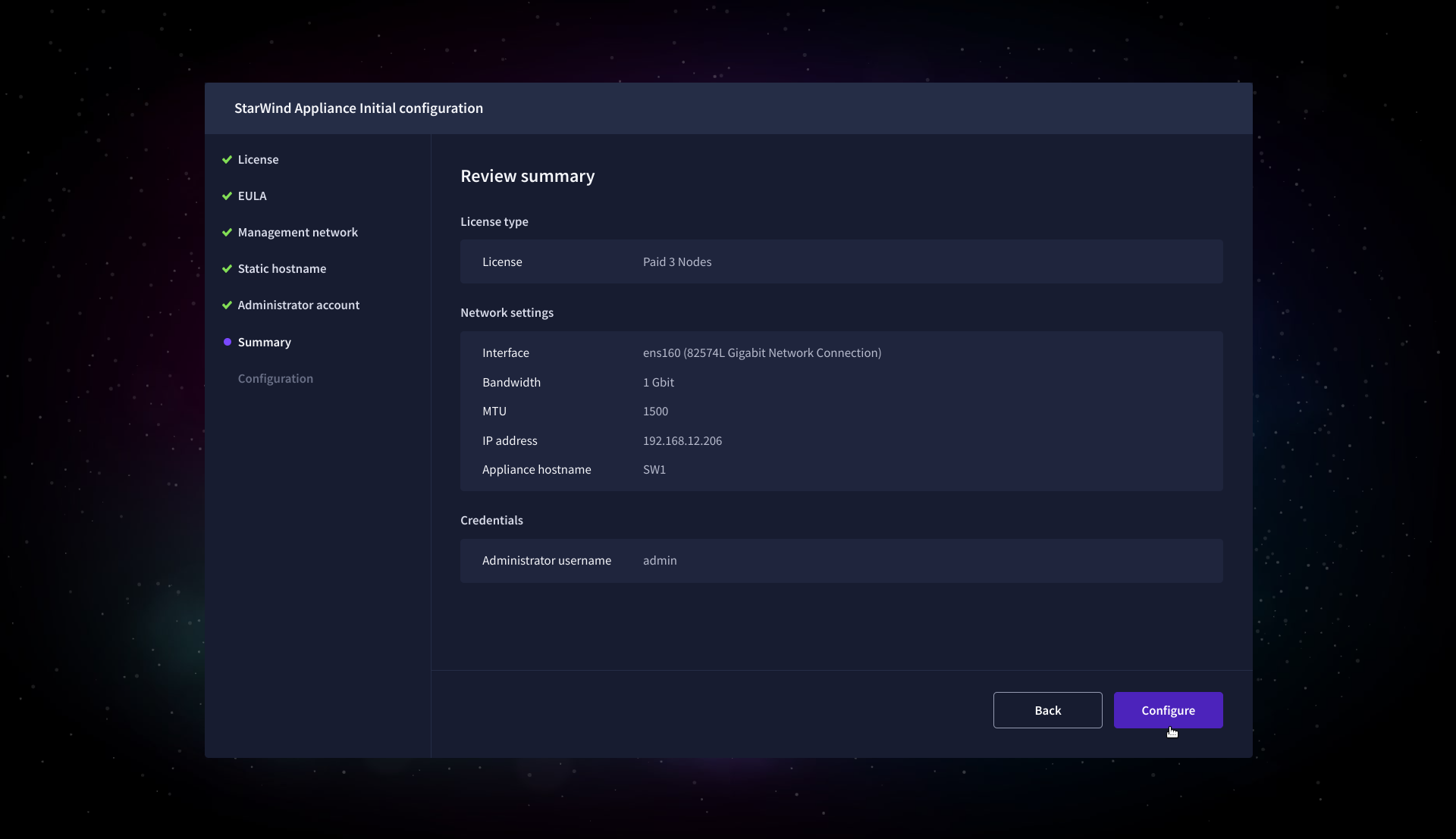
10. Wait until the Initial Configuration Wizard configures StarWind Virtual SAN for you.
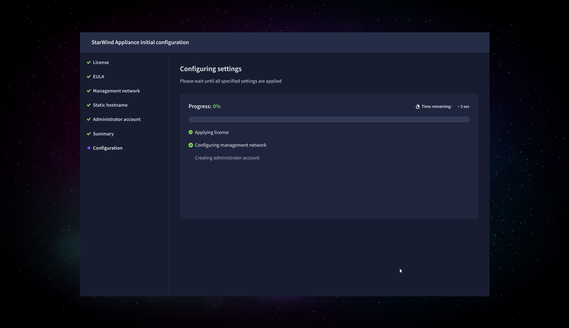
11. Please standby until the Initial Configuration Wizard configures StarWind VSAN for you.
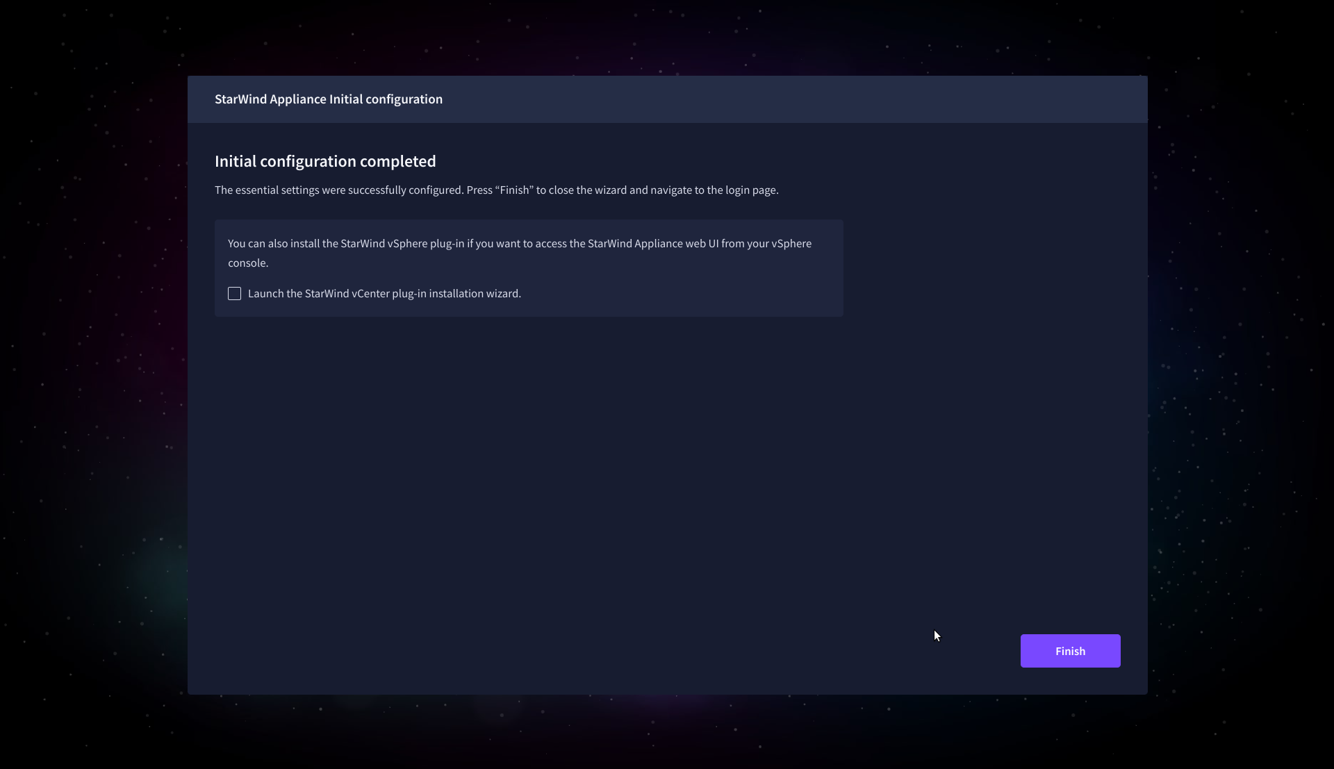
12. After the configuration process is completed, click Finish to install the StarWind vCenter Plugin immediately, or uncheck the checkbox to skip this step and proceed to the Login page.
13. Repeat steps 1 through 12 on each Windows Server host.
Add Appliance
To create replicated, highly available storage, add partner appliances that use the same StarWind Virtual SAN license key.
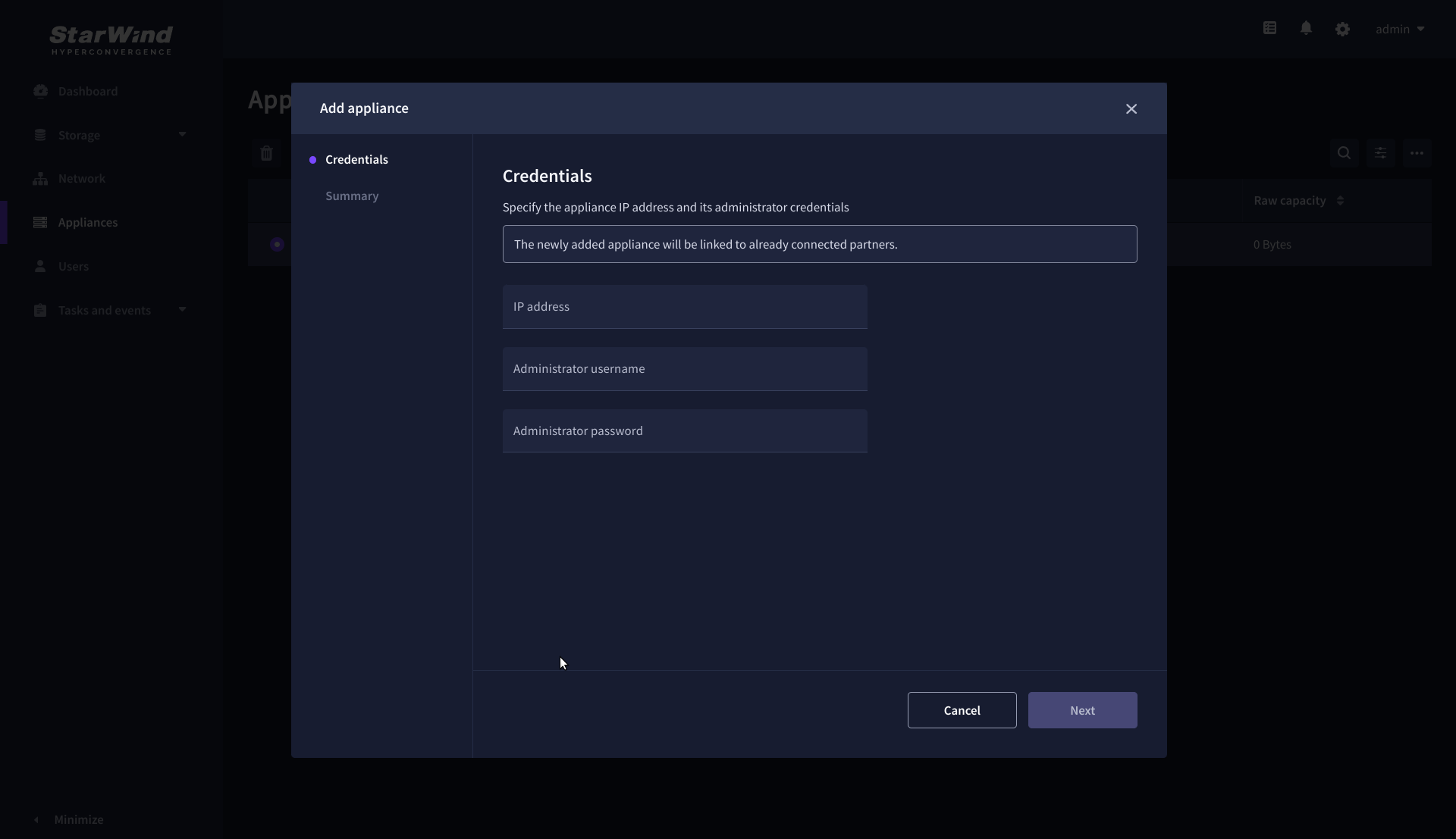
1. Navigate to the Appliances page and click Add to open the Add appliance wizard.
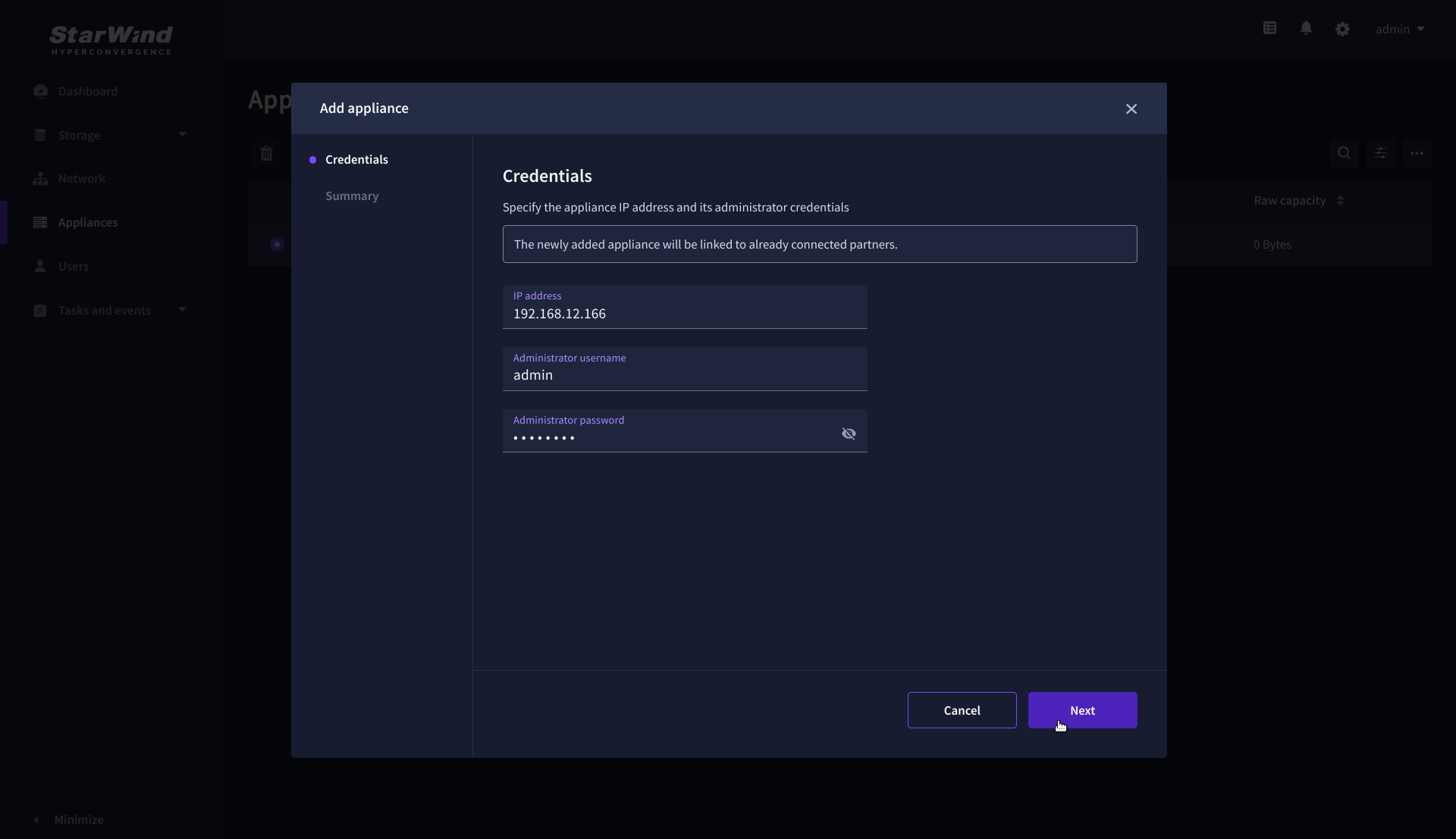
2. On the Credentials step, enter the IP address and credentials for the partner StarWind Virtual SAN appliance, then click Next.
3. Provide credentials of partner appliance.
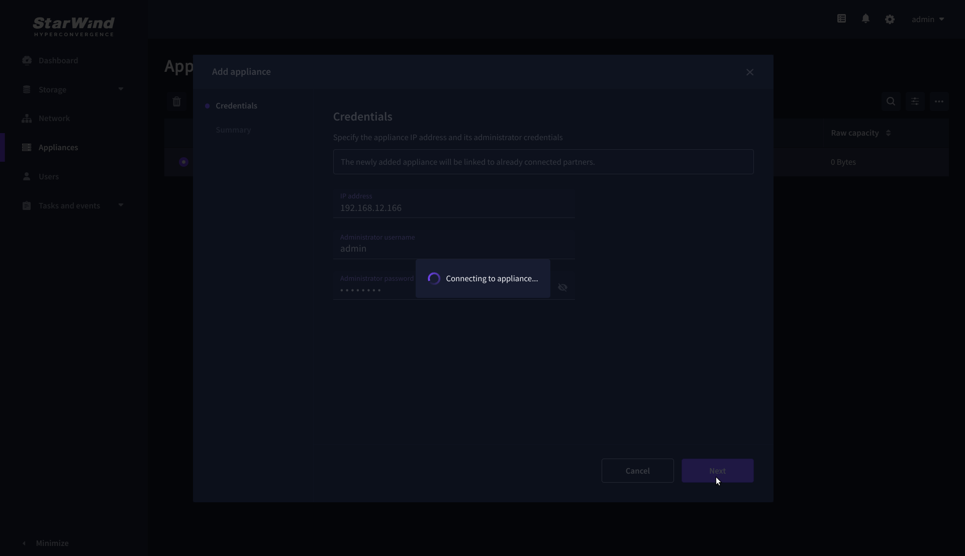
4. Wait for the connection to be established and the settings to be validated
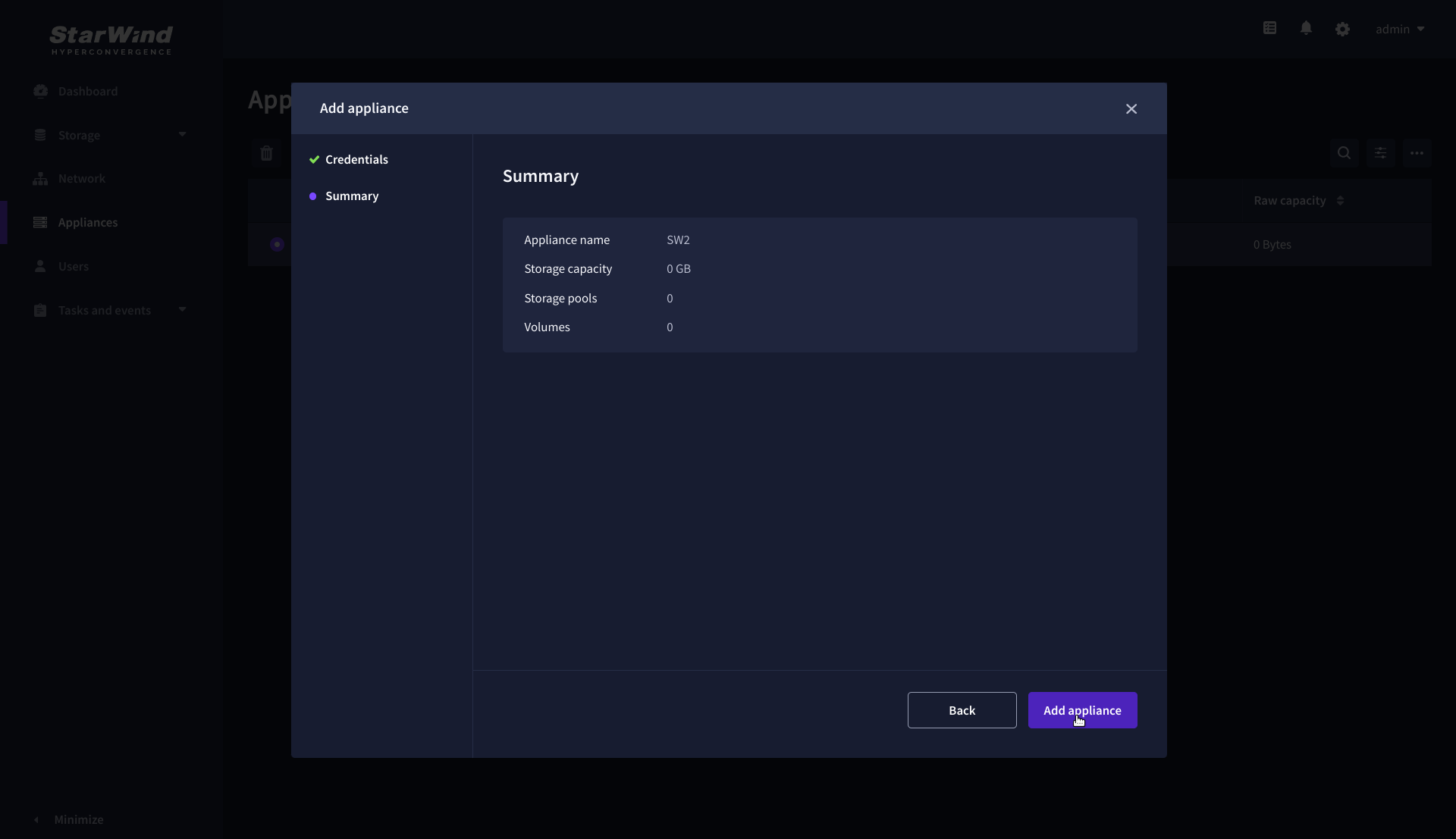
5. On the Summary step, review the properties of the partner appliance, then click Add Appliance.
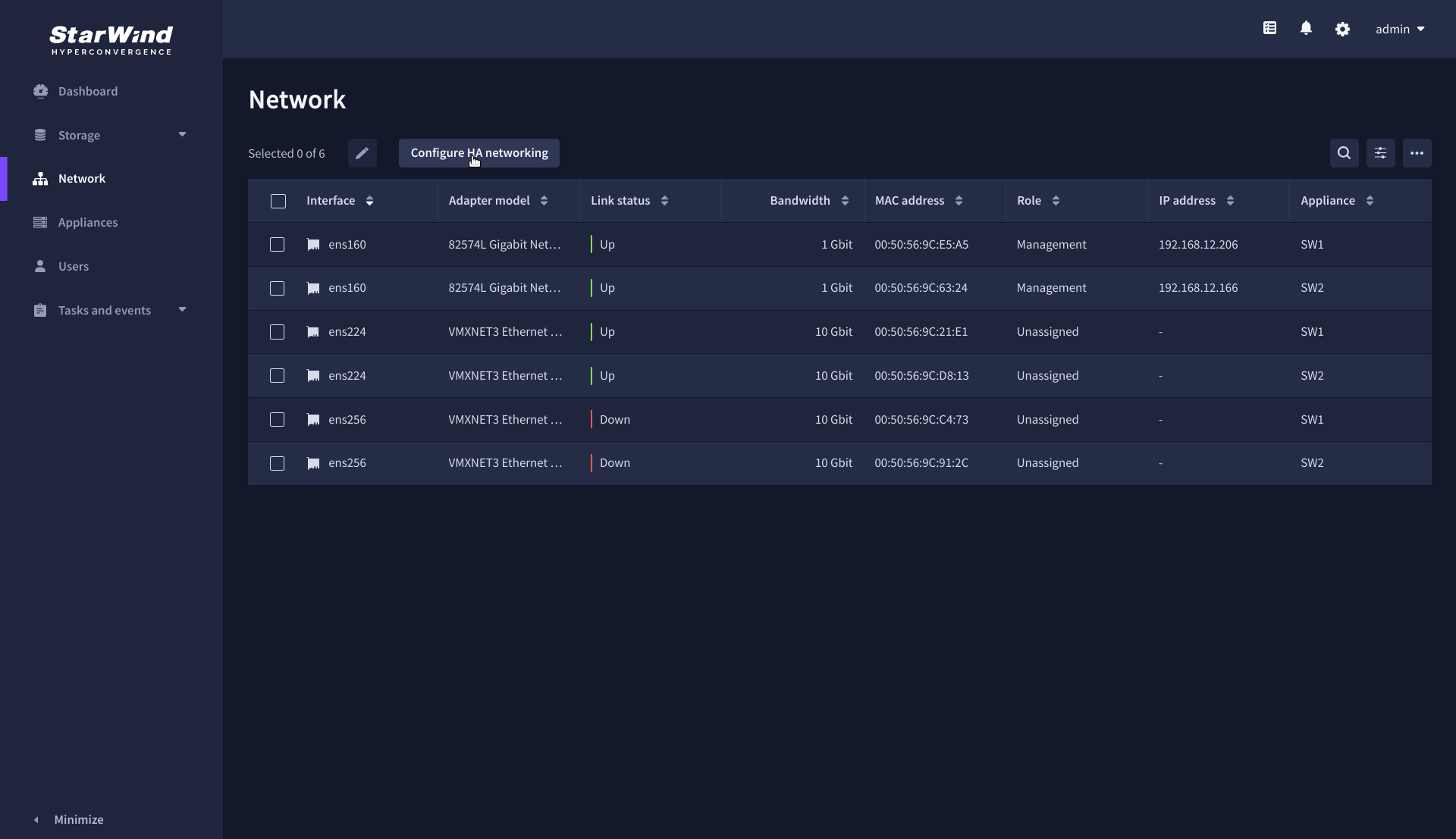
Configure HA networking
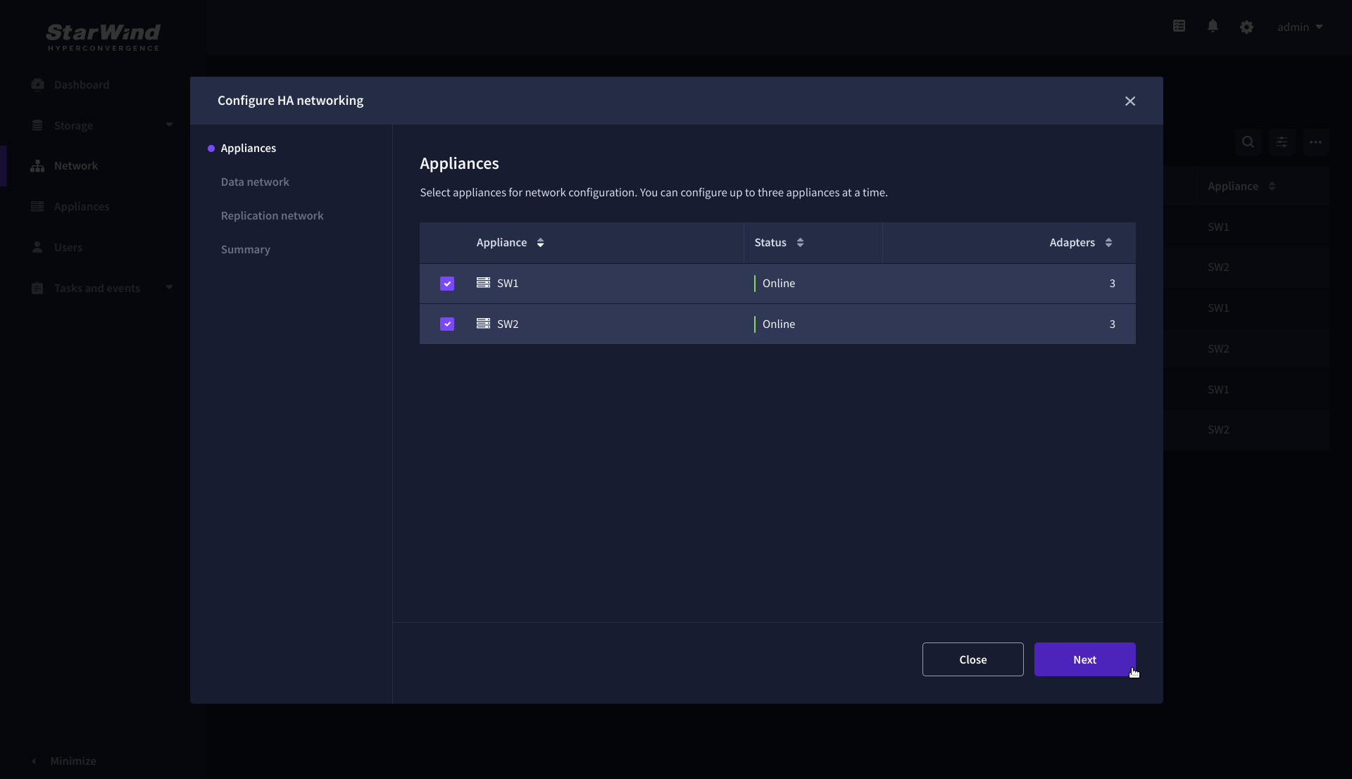
1. Navigate to the Network page and open Configure HA networking wizard.
2. On the Appliances step, select either 2 partner appliances to configure two-way replication, or 3 appliances for three-way replication, then click Next.
NOTE: The number of appliances in the cluster is limited by your StarWind Virtual SAN license.
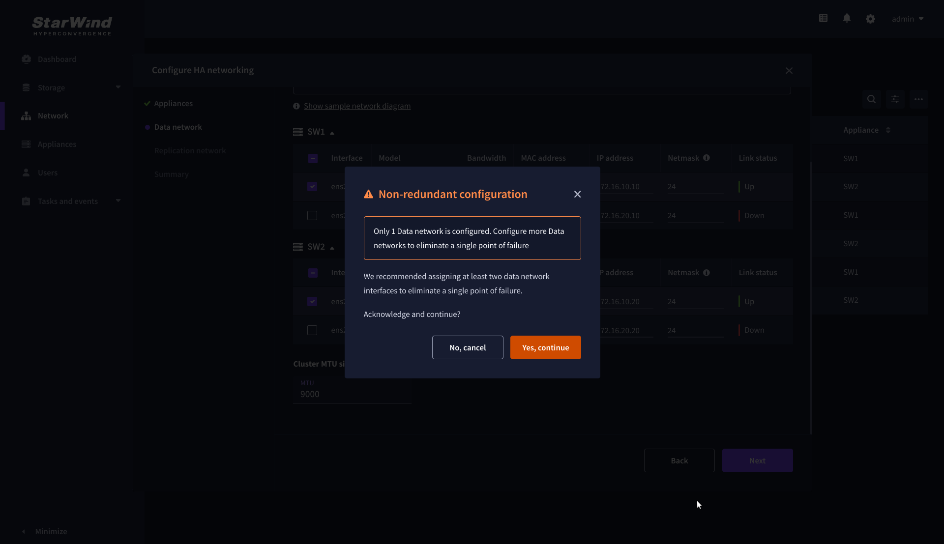
3. On the Data Network step, select the network interfaces designated to carry iSCSI or NVMe-oF storage traffic. Assign and configure at least one interface on each appliance (in our example: 172.16.10.10 and 172.16.10.20) with a static IP address in a unique network (subnet), specify the subnet mask and Cluster MTU size.
IMPORTANT: For a redundant, high-availability configuration, configure at least 2 network interfaces on each appliance. Ensure that the Data Network interfaces are interconnected between appliances through multiple direct links or via redundant switches.
4. Assign MTU value on all selected network adapters, e.g. 1500 or 9000 bytes. If you are using network switches with the selected Data Network adapters, ensure that they are configured with the same MTU size value. In case of MTU settings mismatch, stability and performance issues might occur on the whole setup.
NOTE: Setting MTU to 9000 bytes on some physical adapters (like Intel Ethernet Network Adapter X710, Broadcom network adapters, etc.) might cause stability and performance issues depending on the installed network driver. To avoid them, use 1500 bytes MTU size or install the stable version of the driver.
5. Once configured, click Next to validate network settings.

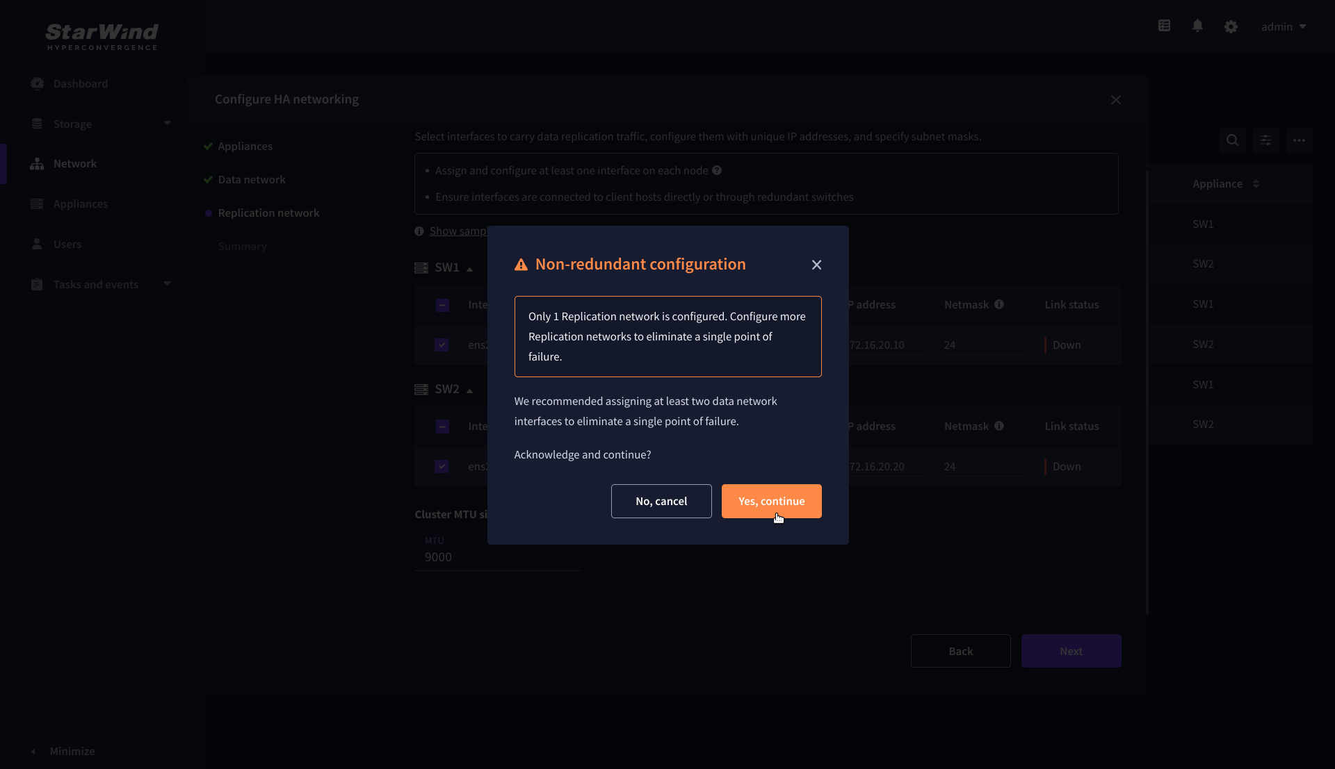
6. The warning might appear if a single data interface is configured. Click Yes, continue to proceed with the configuration.
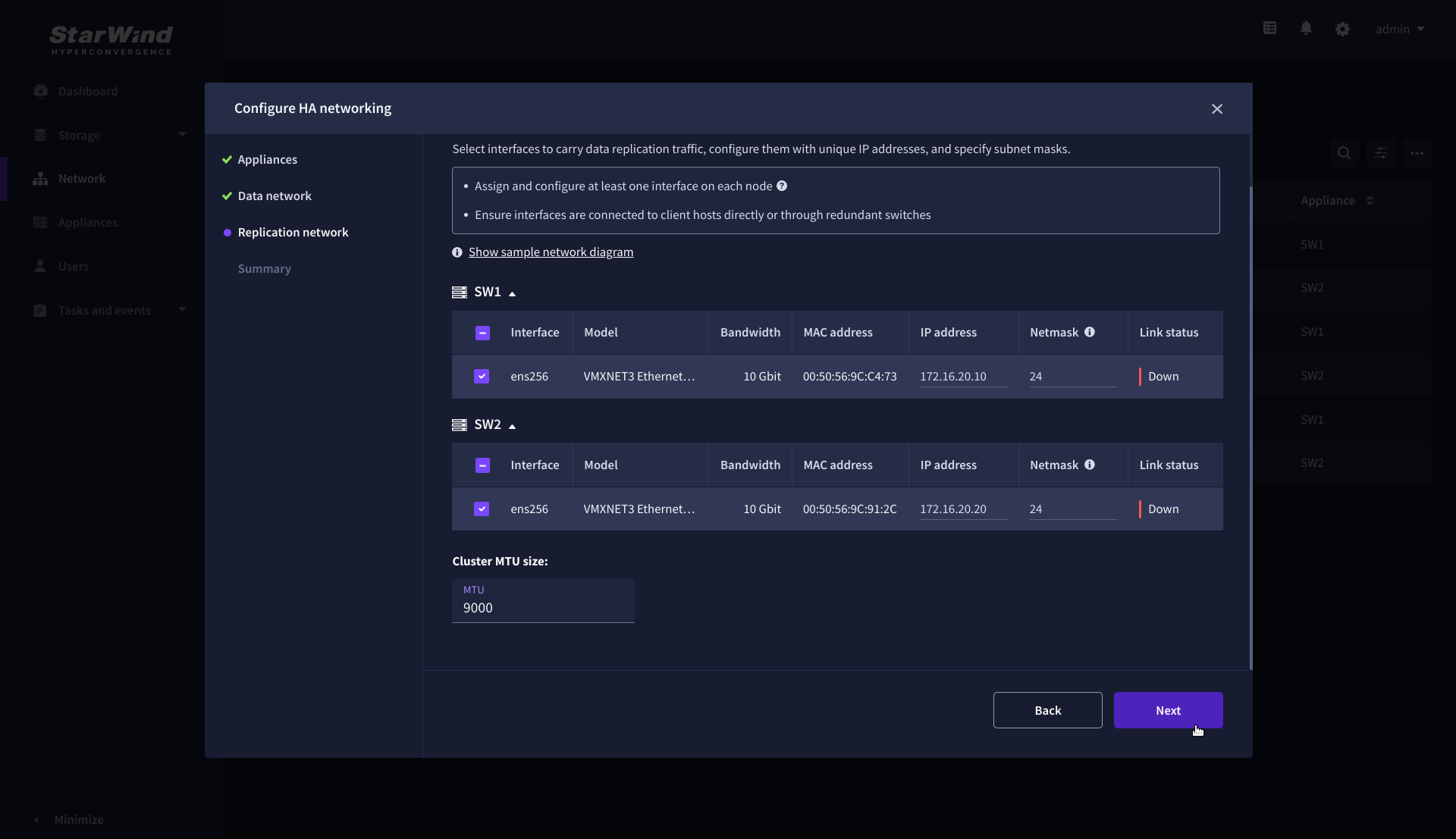
7. On the Replication Network step, select the network interfaces designated to carry the traffic for synchronous replication. Assign and configure at least one interface on each appliance with a static IP address in a unique network (subnet), specify the subnet mask and Cluster MTU size.
IMPORTANT: For a redundant, high-availability configuration, configure at least 2 network interfaces on each appliance. Ensure that the Replication Network interfaces are interconnected between appliances through multiple direct links or via redundant switches.
8. Assign MTU value on all selected network adapters, e.g. 1500 or 9000 bytes. If you are using network switches with the selected Replication Network adapters, ensure that they are configured with the same MTU size value. In case of MTU settings mismatch, stability and performance issues might occur on the whole setup.
NOTE: Setting MTU to 9000 bytes on some physical adapters (like Intel Ethernet Network Adapter X710, Broadcom network adapters, etc.) might cause stability and performance issues depending on the installed network driver. To avoid them, use 1500 bytes MTU size or install the stable version of the driver.
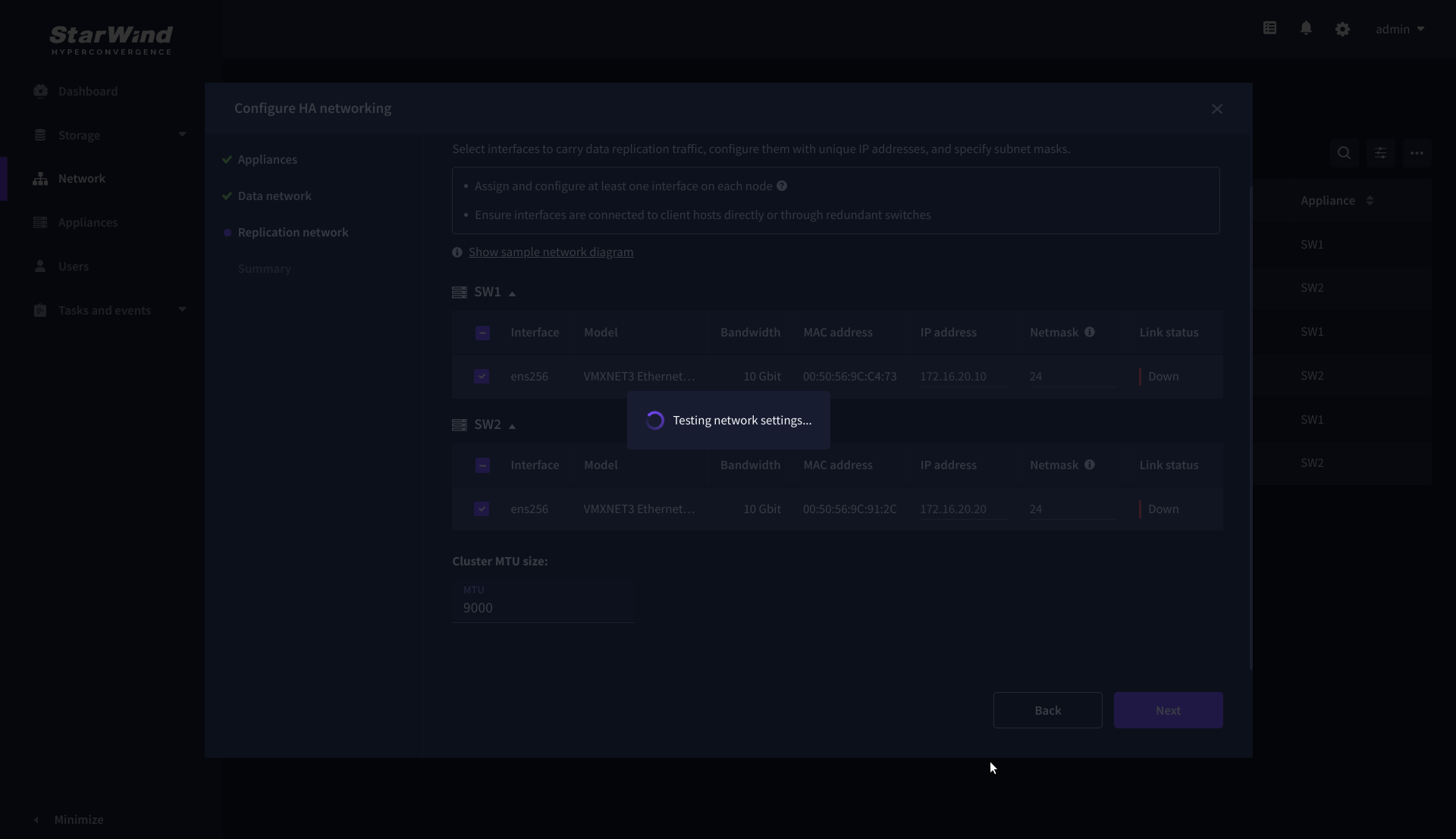
9. Once configured, click Next to validate network settings.
10. If only one Replication Network interface is configured on each partner appliance, a warning message will pop up. Click Yes, continue to acknowledge the warning and proceed.
11. Wait for the configuration completion.
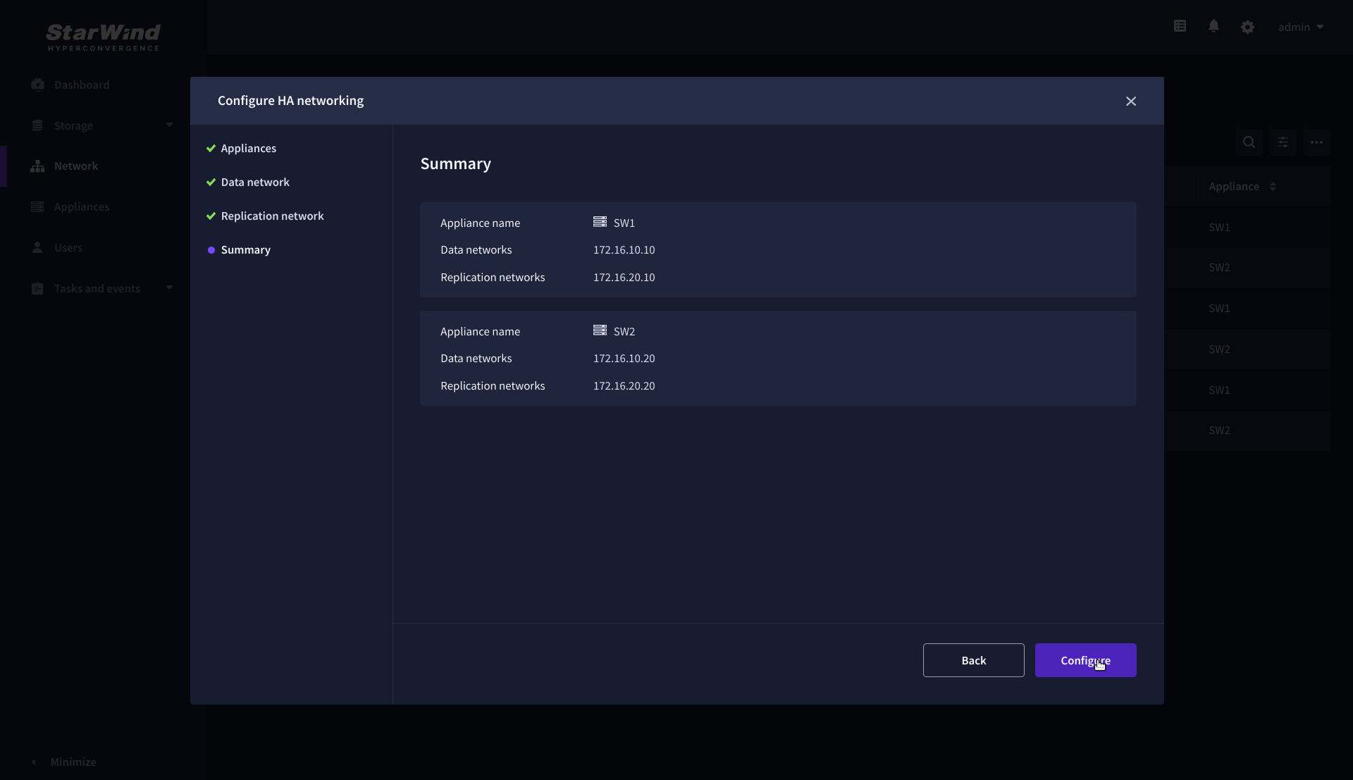
12. On the Summary step, review the specified network settings and click Configure to apply the changes.
Add physical disks
Attach physical storage to StarWind Virtual SAN Controller VM:
- Ensure that all physical drives are connected through an HBA or RAID controller.
- To get the optimal storage performance, add HBA, RAID controllers, or NVMe SSD drives to StarWind CVM via a passthrough device.
For detailed instructions, refer to Microsoft’s documentation on DDA. Also, find the storage provisioning guidelines in the KB article.
Create Storage Pool
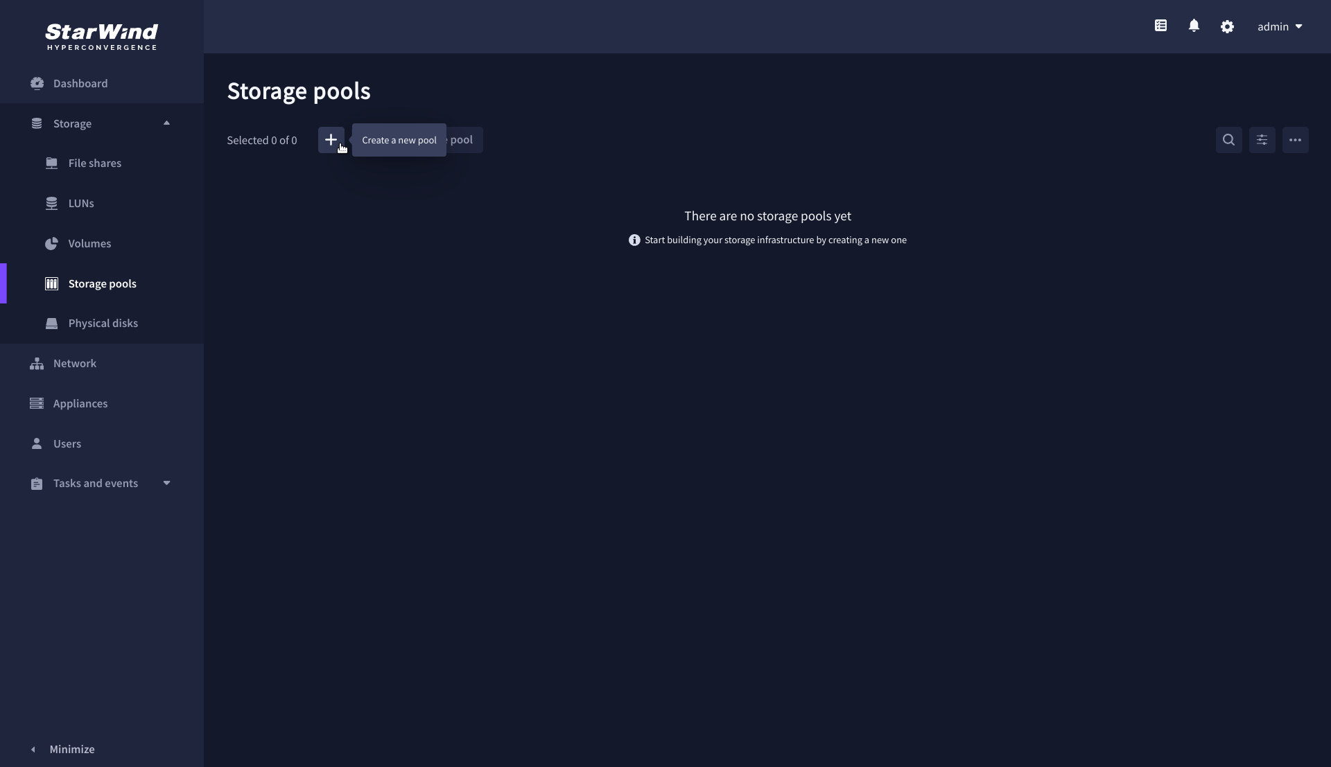
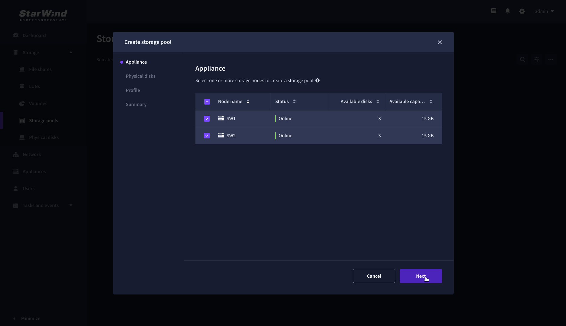
1. Navigate to the Storage pools page and click the + button to open the Create storage pool wizard .
2. On the Appliance step, select partner appliances on which to create new storage pools, then click Next.
NOTE: Select 2 appliances for configuring storage pools if you are deploying a two-node cluster with two-way replication, or select 3 appliances for configuring a three-node cluster with a three-way mirror.
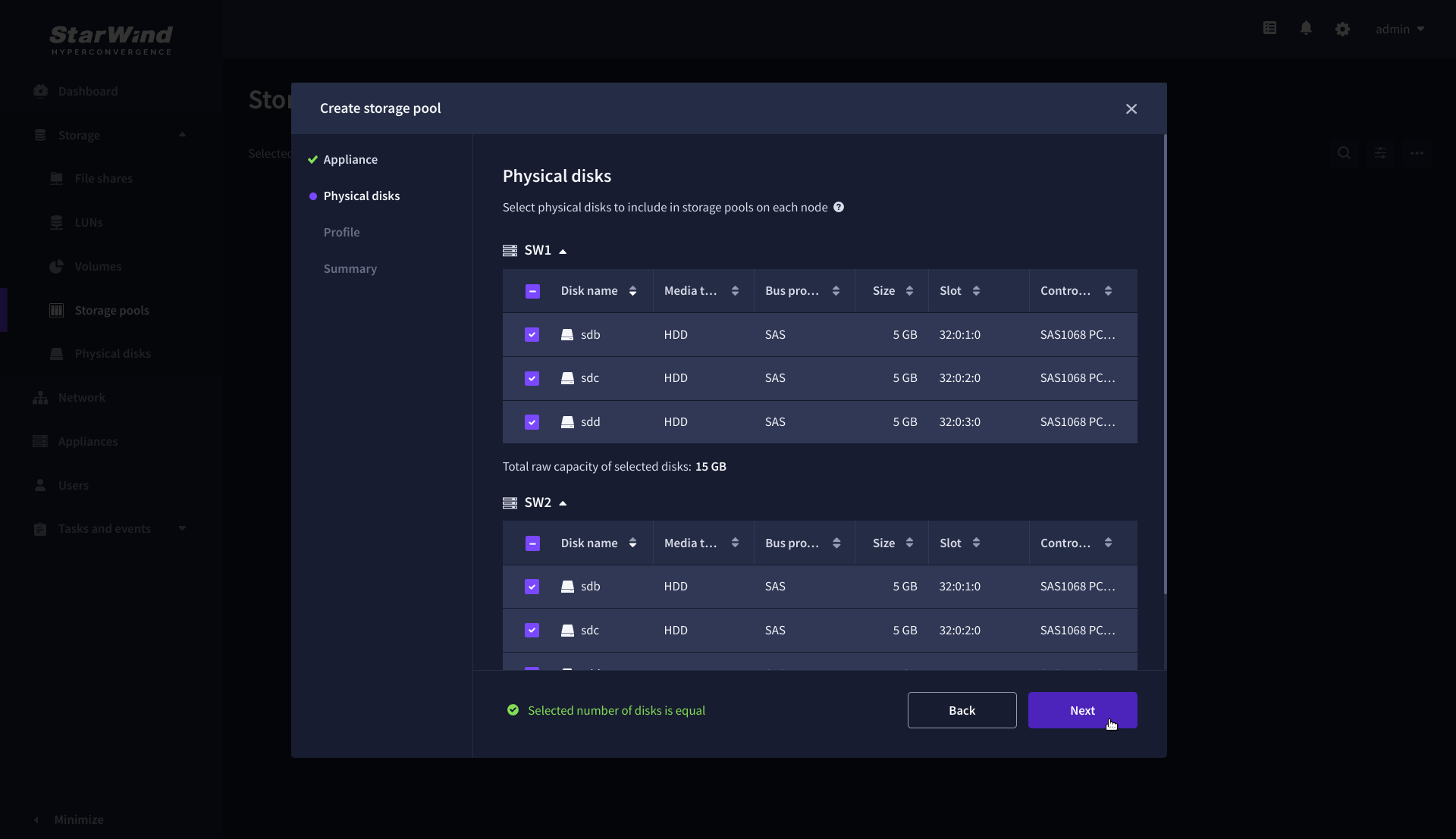
3. On the Physical disks step, select physical disks to be pooled on each node, then click Next.
IMPORTANT: Select an identical type and number of disks on each appliance to create storage pools with a uniform configuration.
4. On the Profile step, select one of the preconfigured storage profiles, or choose Manual to configure the storage pool manually based on your redundancy, capacity, and performance requirements, then click Next.
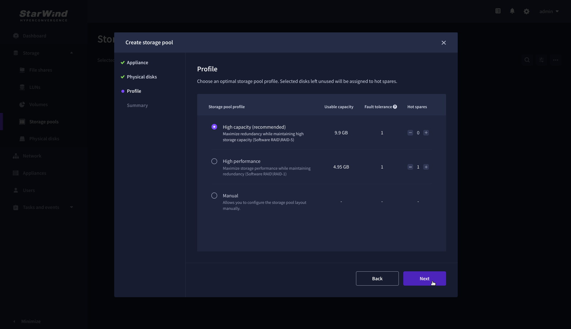
NOTE: Hardware RAID, Linux Software RAID, and ZFS storage pools are supported. To simplify the configuration of storage pools, preconfigured storage profiles are provided. These profiles recommend a pool type and layout based on the attached storage:
- High capacity – creates Linux Software RAID-5 to maximize storage capacity while maintaining redundancy.
- High performance – creates Linux Software RAID-10 to maximize storage performance while maintaining redundancy.
- Hardware RAID – configures a hardware RAID virtual disk as a storage pool. This option is available only if a hardware RAID controller is passed through to the StarWind Virtual SAN.
- Better redundancy – creates ZFS Striped RAID-Z2 (RAID 60) to maximize redundancy while maintaining high storage capacity.
- Manual – allows users to configure any storage pool type and layout with the attached storage.
5. On the Summary step, review the storage pool settings and click Create to configure new storage pools on the selected appliances.
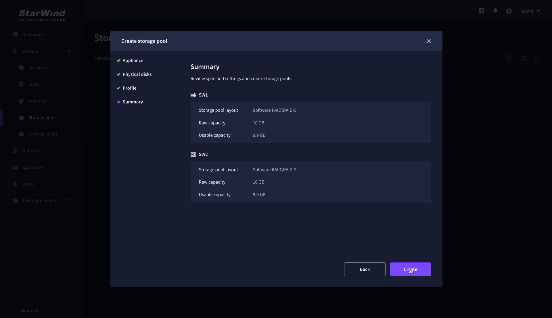
NOTE: The storage pool configuration may take some time, depending on the type of pooled storage and the total storage capacity. Once the pools are created, a notification will appear in the upper right corner of the Web UI.
IMPORTANT: In some cases, additional tweaks are required to optimize the storage performance of the disks added to the Controller Virtual Machine. Please follow the steps in this KB to change the scheduler type depending on the disks type: https://knowledgebase.starwindsoftware.com/guidance/starwind-vsan-for-vsphere-changing-linux-i-o-scheduler-to-optimize-storage-performance/
Create Volume
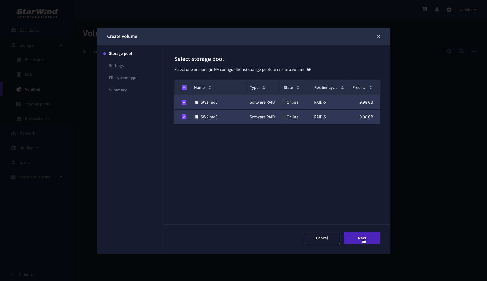
1. Navigate to the Volumes page and click the + button to open the Create volume wizard.

2. On the Storage pool step, select partner appliances on which to create new volumes, then click Next.
NOTE: Select 2 appliances for configuring volumes if you are deploying a two-node cluster with two-way replication, or select 3 appliances for configuring a three-node cluster with a three-way mirror.
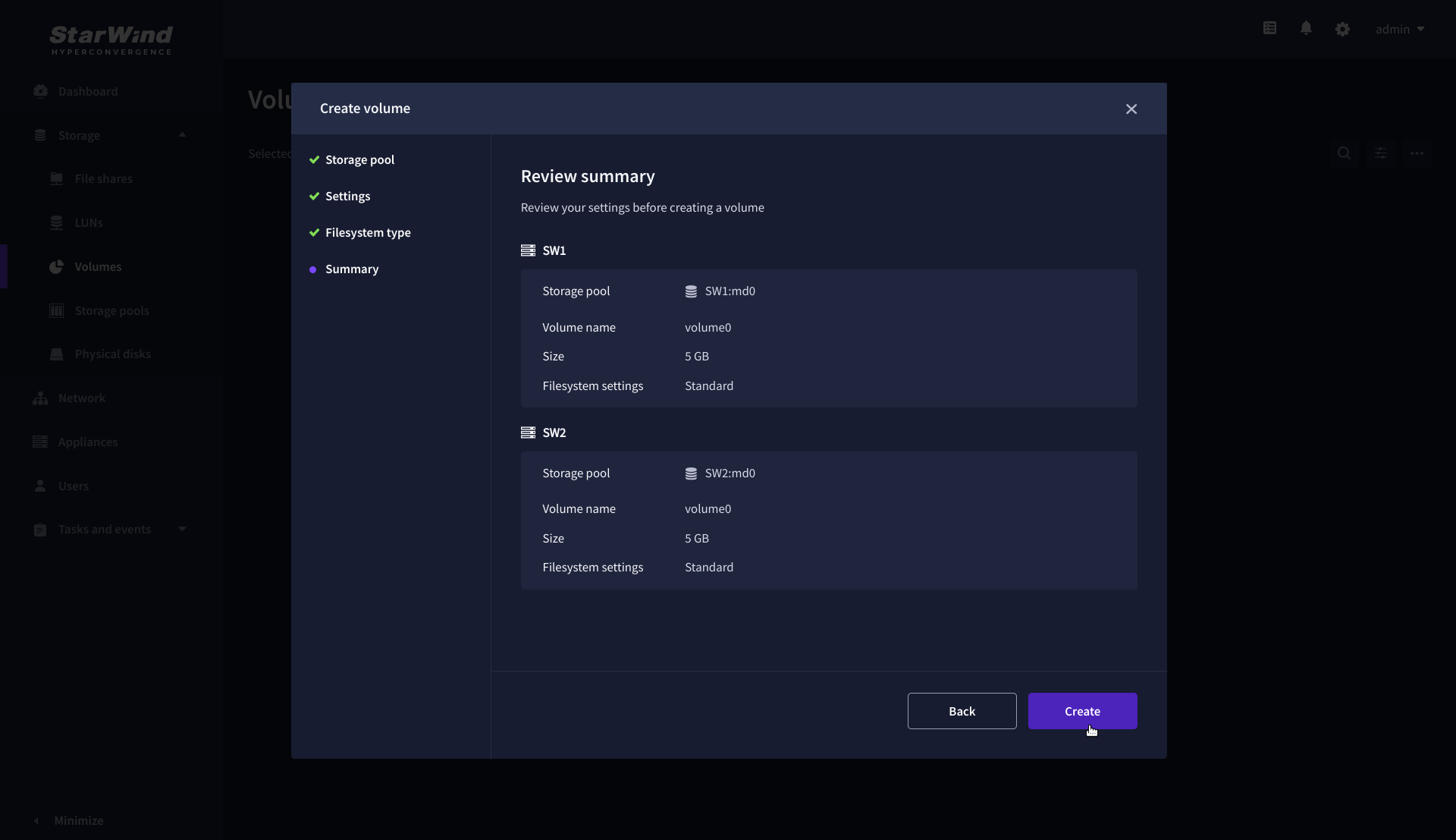
3. On the Settings step, specify the volume name and size, then click Next.

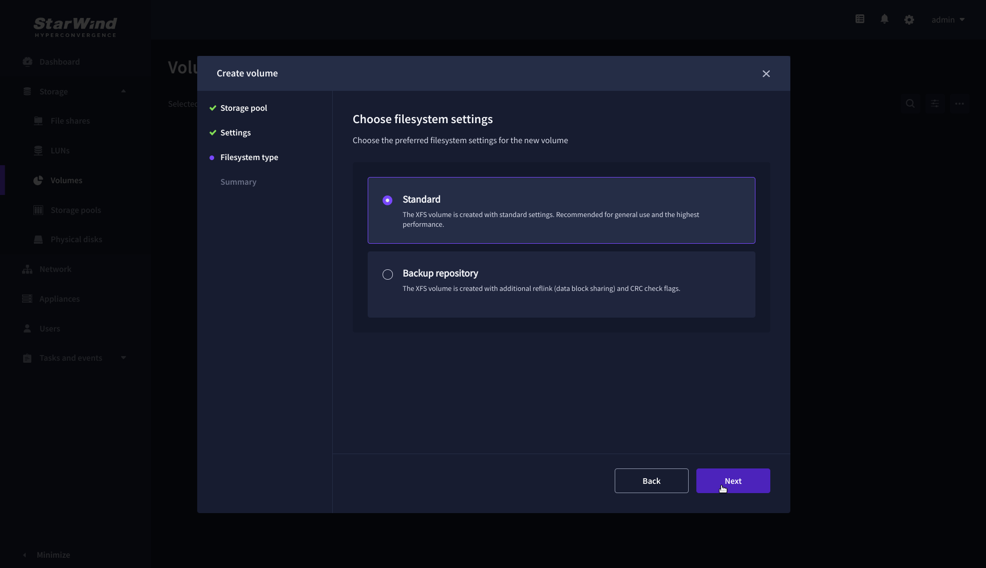
4. On the Filesystem type step, select Standard, then click Next.
5. Review Summary and click the Create button to create the pool.
Create HA LUN using WebUI
This section describes how to create LUN in Web UI. This option is available for the setups with Commercial, Trial, and NFR licenses applied.
For setups with a Free license applied, the PowerShell script should be used to create the LUN – please follow the steps described in the section: Create StarWind HA LUNs using PowerShell
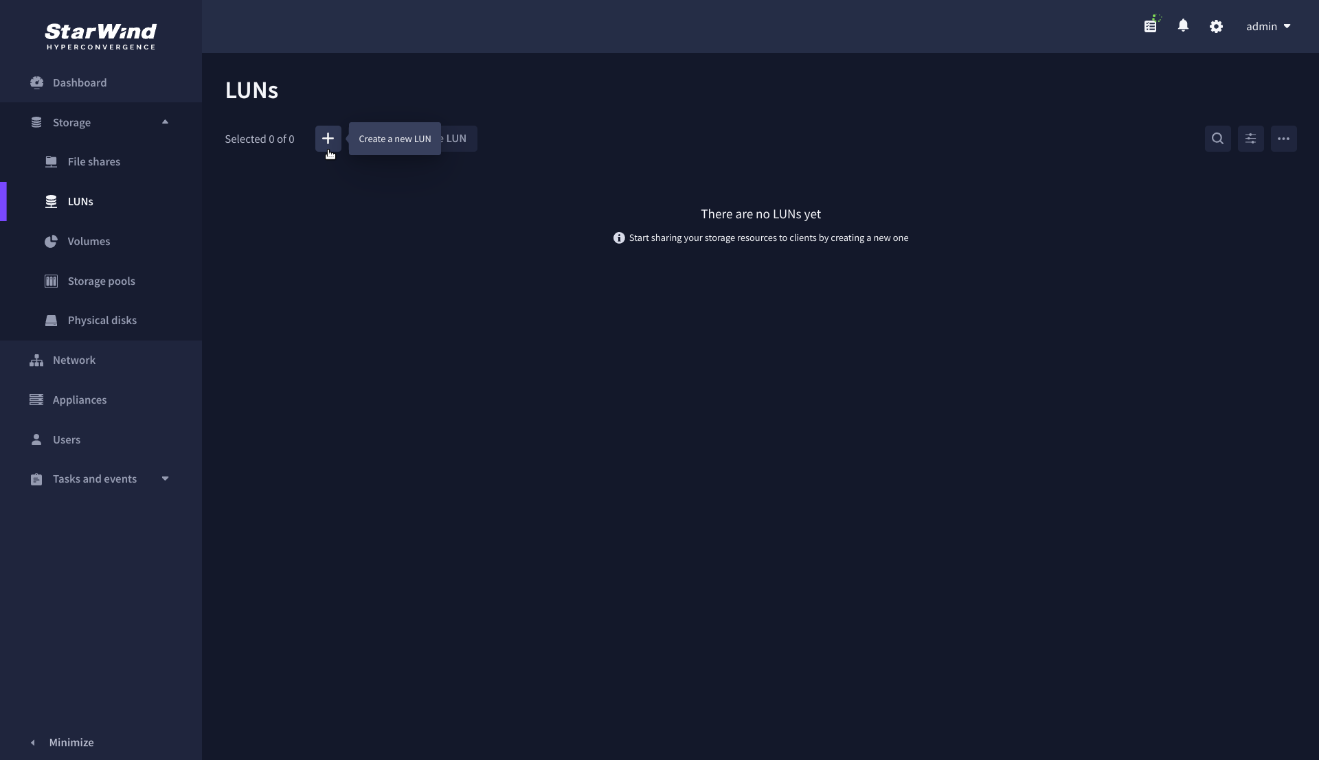
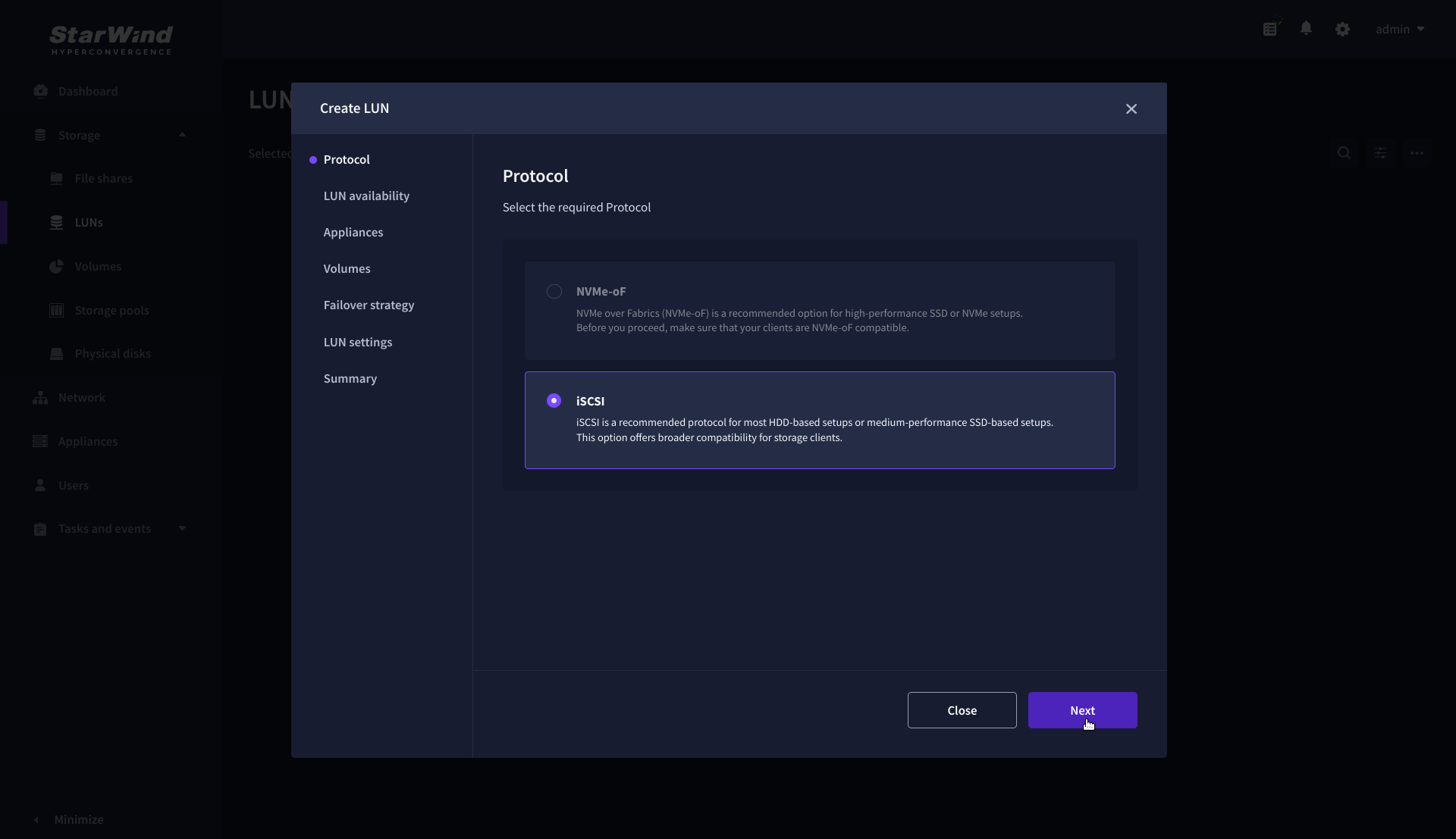
1. Navigate to the LUNs page and click the + button to open the Create LUN wizard.
2. On the Protocols step, select the preferred storage protocol and click Next.
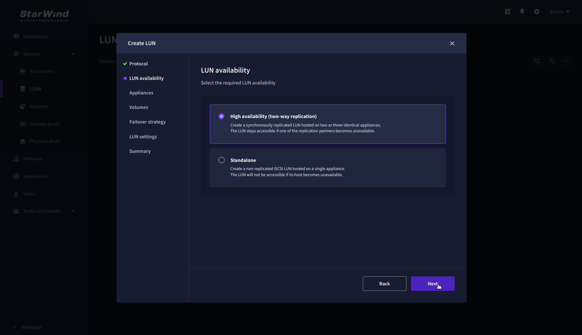
3. On the LUN availability step, select the High availability and click Next.
NOTE: The availability options for a LUN can be Standalone (without replication) or High Availability (with 2-way or 3-way replication), and are determined by the StarWind Virtual SAN license.
Below are the steps for creating a high-availability iSCSI LUN.
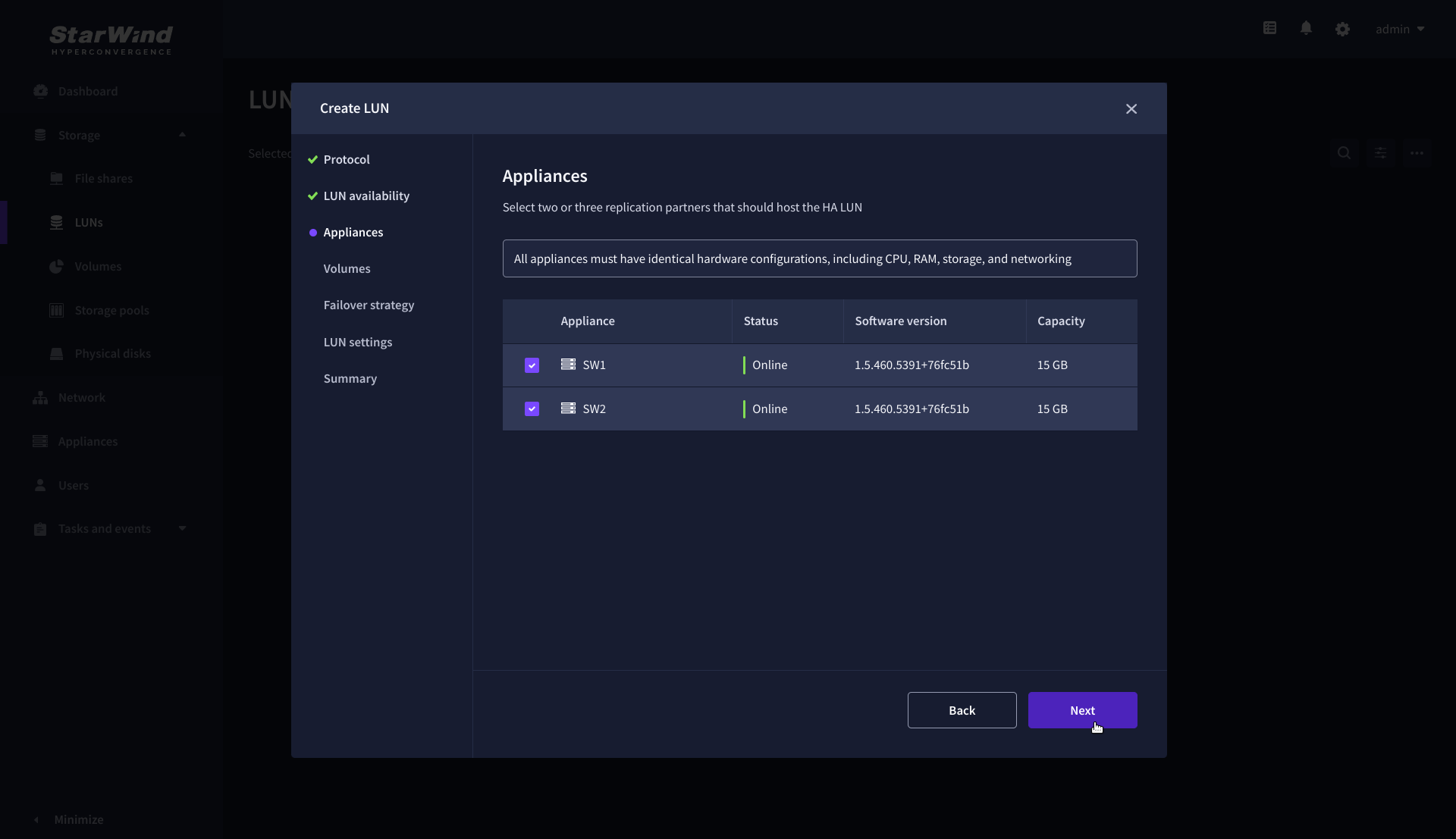
4. On the Appliances step, select partner appliances that will host new LUNs and click Next.
IMPORTANT: Selected partner appliances must have identical hardware configurations, including CPU, RAM, storage, and networking.
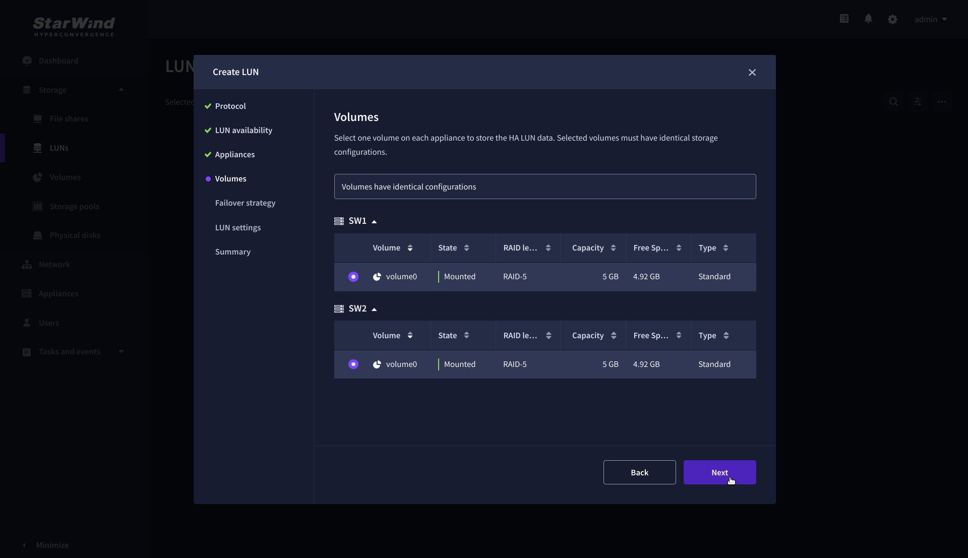
5. On the Volumes step, select the volumes for storing data on the partner appliances and click Next.
IMPORTANT: For optimal performance, the selected volumes must have identical underlying storage configurations.
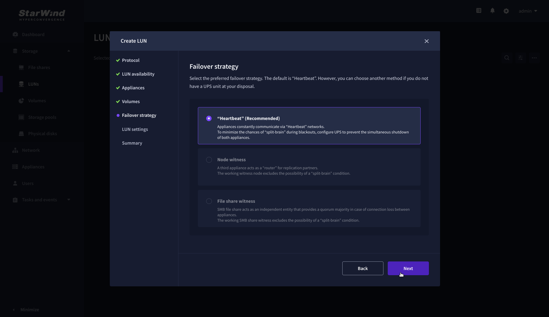
6. On the Failover strategy step, select the preferred failover strategy and click Next.
NOTE: The failover strategies for a LUN can be Heartbeat or Node Majority. In case of 2-nodes setup and None Majority failover strategy, Node witness (requires an additional third witness node), or File share witness (requires an external file share) should be configured. These options are determined by StarWind Virtual SAN license and setup configuration. Below are the steps for configuring the Heartbeat failover strategy in a two-node cluster.
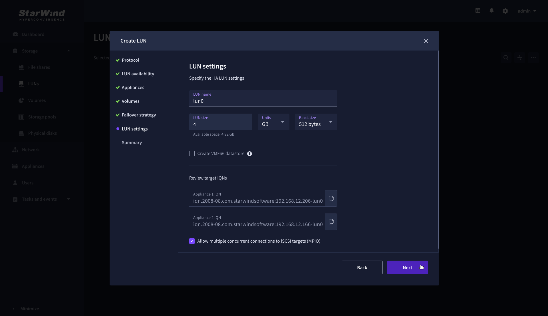
7. On the LUN settings step, specify the LUN name, size, block size, then click Next.
NOTE: For high-availability configurations, ensure that MPIO checkbox is selected.
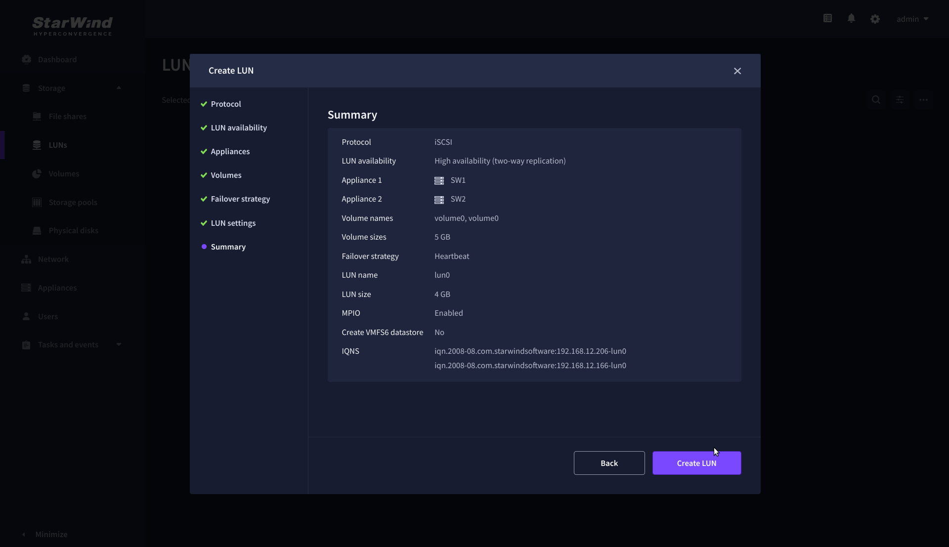
8. On the Summary step, review the LUN settings and click Create to configure new LUNs on the selected volumes.
Creating StarWind HA LUNs using PowerShell
1. Open PowerShell ISE as Administrator.
2. Open StarWindX sample CreateHA_2.ps1 using PowerShell ISE. It can be found here: C:\Program Files\StarWind Software\StarWind\StarWindX\Samples\
NOTE: The script below creates a 1TB size 2-node HA device with a heartbeat failover strategy on StarWind nodes with management IP addresses 192.168.0.1 and 192.168.0.2 correspondingly.
The IP addresses 172.16.10.1 and 172.16.10.2 are used as heartbeat interfaces along with 192.168.0.1 and 192.168.0.2 for redundancy.
The IP addresses 172.16.20.1 and 172.16.20.2 on each node correspondingly as well as 172.16.21.1 and 172.16.21.2 are used for the devices synchronization between the nodes.
The script does not create a directory. Make sure you create the directory listed as $imagePath value before running the script.
Make sure to open 3261 and 3260 ports.
The same approach applies to CreateHA_3.ps1 which allow to create a 3-way replica HA device.
3. Configure script parameters according to the following example:
param($addr="192.168.0.1", $port=3261, $user="root", $password="starwind",
      $addr2="192.168.0.2", $port2=$port, $user2=$user, $password2=$password,
#common
      $initMethod="NotSynchronize",
      $size=1048576,
      $sectorSize=512,
      $failover=0,
      $bmpType=1,
      $bmpStrategy=0,
#primary node
      $imagePath="/mnt/sdb1/volume1",
      $imageName="device1",
      $createImage=$true,
      $storageName="",
      $targetAlias="target1",
      $poolName="pool1",
      $syncSessionCount=1,
      $aluaOptimized=$true,
      $cacheMode="none",
      $cacheSize=0,
      $syncInterface="#p2=172.16.20.2:3260,172.16.21.2:3260",
      $hbInterface="#p2=172.16.10.2:3260,192.168.0.2:3260",
      $createTarget=$true,
      $bmpFolderPath="",
#secondary node
      $imagePath2="/mnt/sdb1/volume1",
      $imageName2="device1",
      $createImage2=$true,
      $storageName2="",
      $targetAlias2="target1",
      $poolName2="pool1",
      $syncSessionCount2=1,
      $aluaOptimized2=$false,
      $cacheMode2=$cacheMode,
      $cacheSize2=$cacheSize,
      $syncInterface2="#p1=172.16.20.1:3260,172.16.21.1:3260",
      $hbInterface2="#p1=172.16.10.1:3260,192.168.0.1:3260",
      $createTarget2=$true,
      $bmpFolderPath2=""
 )

Import-Module StarWindX

try
{
	Enable-SWXLog -level SW_LOG_LEVEL_DEBUG

	$server = New-SWServer -host $addr -port $port -user $user -password $password

	$server.Connect()

	$firstNode = new-Object Node

	$firstNode.HostName = $addr
	$firstNode.HostPort = $port
	$firstNode.Login = $user
	$firstNode.Password = $password
	$firstNode.ImagePath = $imagePath
	$firstNode.ImageName = $imageName
	$firstNode.Size = $size
	$firstNode.CreateImage = $createImage
	$firstNode.StorageName = $storageName
	$firstNode.TargetAlias = $targetAlias
	$firstNode.AutoSynch = $autoSynch
	$firstNode.SyncInterface = $syncInterface
	$firstNode.HBInterface = $hbInterface
	$firstNode.PoolName = $poolName
	$firstNode.SyncSessionCount = $syncSessionCount
	$firstNode.ALUAOptimized = $aluaOptimized
	$firstNode.CacheMode = $cacheMode
	$firstNode.CacheSize = $cacheSize
	$firstNode.FailoverStrategy = $failover
	$firstNode.CreateTarget = $createTarget
	$firstNode.BitmapStoreType = $bmpType
	$firstNode.BitmapStrategy = $bmpStrategy
	$firstNode.BitmapFolderPath = $bmpFolderPath

	#
	# device sector size. Possible values: 512 or 4096(May be incompatible with some clients!) bytes.
	#
	$firstNode.SectorSize = $sectorSize

	$secondNode = new-Object Node

	$secondNode.HostName = $addr2
	$secondNode.HostPort = $port2
	$secondNode.Login = $user2
	$secondNode.Password = $password2
	$secondNode.ImagePath = $imagePath2
	$secondNode.ImageName = $imageName2
	$secondNode.CreateImage = $createImage2
	$secondNode.StorageName = $storageName2
	$secondNode.TargetAlias = $targetAlias2
	$secondNode.AutoSynch = $autoSynch2
	$secondNode.SyncInterface = $syncInterface2
	$secondNode.HBInterface = $hbInterface2
	$secondNode.SyncSessionCount = $syncSessionCount2
	$secondNode.ALUAOptimized = $aluaOptimized2
	$secondNode.CacheMode = $cacheMode2
	$secondNode.CacheSize = $cacheSize2
	$secondNode.FailoverStrategy = $failover
	$secondNode.CreateTarget = $createTarget2
	$secondNode.BitmapFolderPath = $bmpFolderPath2

	$device = Add-HADevice -server $server -firstNode $firstNode -secondNode $secondNode -initMethod $initMethod

	while ($device.SyncStatus -ne [SwHaSyncStatus]::SW_HA_SYNC_STATUS_SYNC)
	{
		$syncPercent = $device.GetPropertyValue("ha_synch_percent")
	        Write-Host "Synchronizing: $($syncPercent)%" -foreground yellow

		Start-Sleep -m 2000

		$device.Refresh()
	}
}
catch
{
	Write-Host $_ -foreground red
}
finally
{
	$server.Disconnect()
}
Detailed explanation of script parameters:
-addr, -addr2 — partner nodes IP address.
Format: string. Default value: 192.168.0.1, 192.168.0.2
allowed values: localhost, IP-address
-port, -port2 — local and partner node port.
Format: string. Default value: 3261
-user, -user2 — local and partner node user name.
Format: string. Default value: root
-password, -password2 — local and partner node user password.
Format: string. Default value: starwind
#common
-initMethod – set the initial synchronization option.
Format: string.
Values:
Clear – default
NotSynchronize – skips synchronization (works ONLY IF THERE IS NO DATA TO SKIP THE ORIGINAL SYNCHRONIZATION).
SyncFromFirst or SyncFromSecond or SyncFromThird – runs full synchronization from the specific node. Use it for recreating replicas.
-size – set size for HA-device (in MB)
Format: integer. Default value: 12
-sectorSize – set sector size for HA-device
Format: integer. Default value: 512
allowed values: 512, 4096
-failover – set type failover strategy
Format: integer. Default value: 0 (Heartbeat)
allowed values: 0, 1 (Node Majority)
-bmpType – set bitmap type, is set for both partners at once
Format: integer. Default value: 1 (RAM)
allowed values: 1, 2 (DISK)
-bmpStrategy – set journal strategy, is set for both partners at once
Format: integer. Default value: 0
allowed values: 0, 1 – Best Performance (Failure), 2 – Fast Recovery (Continuous)
-storageName is used only if you plan to add the partner to the existing device. For CreateHA_2.ps1 use, leave it as is.
#primary node
-imagePath – set path to store the device file
Format: string. Default value: My computer\C\starwind”. For Linux the following format should be used: “VSA Storage\mnt\mount_point”
-imageName – set name device
Format: string. Default value: masterImg21
-createImage – set create image file
Format: boolean. Default value: true
-targetAlias – set alias for target
Format: string. Default value: targetha21
-poolName – set storage pool. Do not change it and keep default value.
Format: string. Default value: pool1
-aluaOptimized – set Alua Optimized
Format: boolean. Default value: true
-cacheMode – set type L1 cache (optional parameter)
Format: string. Default value: wb
allowed values: none, wb, wt
-cacheSize – set size for L1 cache in MB (optional parameter)
Format: integer. Default value: 128
allowed values: 1 and more
-syncInterface – set sync channel IP-address from partner node
Format: string. Default value: “#p2={0}:3260”
-hbInterface – set heartbeat channel IP-address from partner node
Format: string. Default value: “”
-createTarget – set creating target
Format: string. Default value: true
Even if you do not specify the parameter -createTarget, the target will be created automatically.
If the parameter is set as -createTarget $false, then an attempt will be made to create the device with existing targets, the names of which are specified in the -targetAlias (targets must already be created)
-bmpFolderPath – set path to save bitmap file
Format: string.
#secondary node
-imagePath2 – set path to store the device file
Format: string. Default value: “My computer\C\starwind”. For Linux the following format should be used: “VSA Storage\mnt\mount_point”
-imageName2 – set name device
Format: string. Default value: masterImg21
-createImage2 – set create image file
Format: boolean. Default value: true
-targetAlias2 – set alias for targetFormat: string.
Default value: targetha22
-poolName2 – set storage pool. Do not change it and keep default value.
Format: string. Default value: pool1
-aluaOptimized2 – set Alua Optimized
Format: boolean. Default value: true
-cacheMode2 – set type L1 cache (optional parameter)
Format: string. Default value: wb
allowed values: wb, wt
-cacheSize2 – set size for L1 cache in MB (optional parameter)
Format: integer. Default value: 128
allowed values: 1 and more
-syncInterface2 – set sync channel IP-address from partner node
Format: string. Default value: “#p1={0}:3260”
-hbInterface2 – set heartbeat channel IP-address from partner node
Format: string. Default value: “”
-createTarget2 – set creating target
Format: string. Default value: true
Even if you do not specify the parameter -createTarget, the target will be created automatically.If the parameter is set as -createTarget $false, then an attempt will be made to create the device with existing targets, the names of which are specified in the -targetAlias (targets must already be created)
-bmpFolderPath2 – set path to save bitmap file
Format: string.
IMPORTANT: If the script should be executed again with the same parameters, (for example, the first time execution has failed) make sure to do the following for one node at a time before the next attempt to execute the script:
1. Stop StarWind Service:
sudo systemctl stop starwind-virtual-san2. Go to /opt/starwind/starwind-virtual-san/drive_c/starwind/headers and delete the headers you do not need.
3. Go to the underlying storage specified as $imagePath and delete the header and imagefile there.
4. Go to the folder with StarWind.cfg (/opt/starwind/starwind-virtual-san/drive_c/starwind/StarWind.cfg ) and copy it.
5. Edit StarWind.cfg:
sudo nano /opt/starwind/starwind-virtual-san/drive_c/starwind/StarWind.cfg6. Navigate under <targets>, remove target you do not need.
7. Navigate under <devices>, and remove the device entry you do not need.
8. Start the service:
sudo systemctl start starwind-virtual-san9. Wait for the devices synchronization.
10. Repeat for the remaining StarWind VSAN instance.
Selecting the Failover Strategy
StarWind provides 2 options for configuring a failover strategy:
Heartbeat
The Heartbeat failover strategy allows avoiding the “split-brain” scenario when the HA cluster nodes are unable to synchronize but continue to accept write commands from the initiators independently. It can occur when all synchronization and heartbeat channels disconnect simultaneously, and the partner nodes do not respond to the node’s requests. As a result, StarWind service assumes the partner nodes to be offline and continues operations on a single-node mode using data written to it.
If at least one heartbeat link is online, StarWind services can communicate with each other via this link. The device with the lowest priority will be marked as not synchronized and get subsequently blocked for the further read and write operations until the synchronization channel resumption. At the same time, the partner device on the synchronized node flushes data from the cache to the disk to preserve data integrity in case the node goes down unexpectedly. It is recommended to assign more independent heartbeat channels during the replica creation to improve system stability and avoid the “split-brain” issue.
With the heartbeat failover strategy, the storage cluster will continue working with only one StarWind node available.
Node Majority
The Node Majority failover strategy ensures the synchronization connection without any additional heartbeat links. The failure-handling process occurs when the node has detected the absence of the connection with the partner.
The main requirement for keeping the node operational is an active connection with more than half of the HA device’s nodes. Calculation of the available partners is based on their “votes”.
In case of a two-node HA storage, all nodes will be disconnected if there is a problem on the node itself, or in communication between them. Therefore, the Node Majority failover strategy requires the addition of the third Witness node or file share (SMB) which participates in the nodes count for the majority, but neither contains data on it nor is involved in processing clients’ requests. In case an HA device is replicated between 3 nodes, no Witness node is required.
With Node Majority failover strategy, failure of only one node can be tolerated. If two nodes fail, the third node will also become unavailable to clients’ requests.
Please select the required option:
Provisioning StarWind HA Storage to Hosts
1. Login to Engine and open Storage -> Domain. Click New Domain.
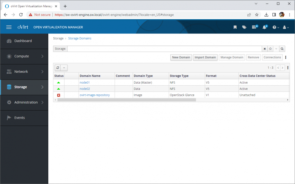
2. Choose Storage Type – iSCSI, Host and Name of Storage Domain. Discover targets via iSCSI links, which were previously configured. Click Login All. 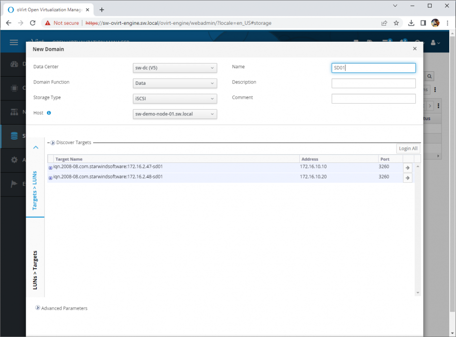
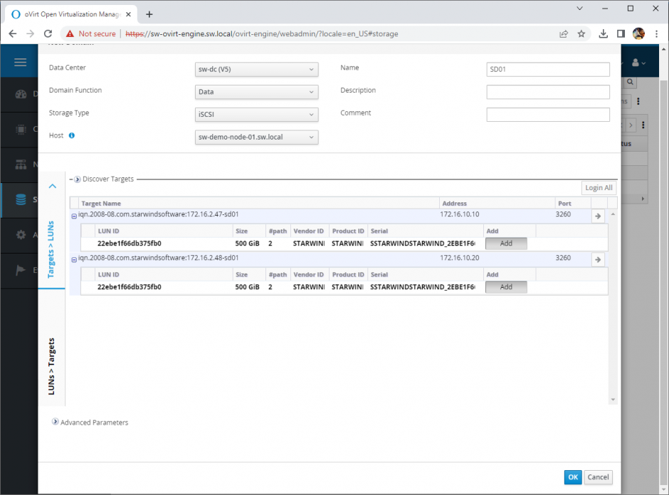
3. Add LUN from each iSCSI target. Click OK.
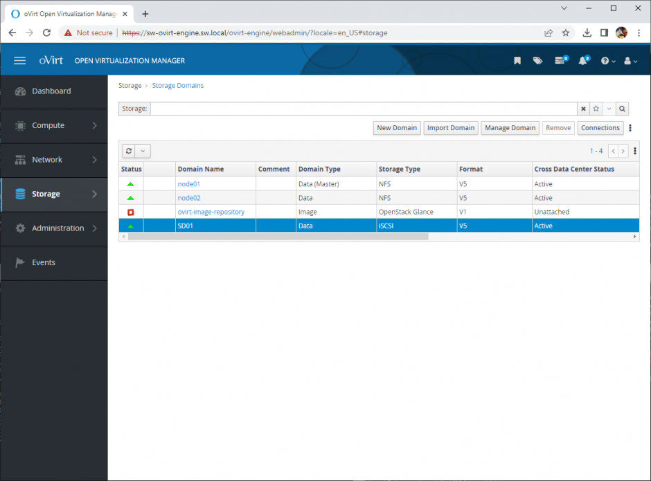
4. Storage Domain will be added to the list of Domain and can be used as a storage for VMs.
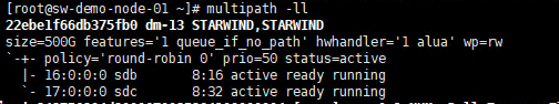
5. Login to each host and verify that multipathing policy has been applied using the following command.
multipath -ll
Conclusion
Deploying and configuring StarWind Virtual SAN CVM within the Red Hat Virtualization [KVM] is an important move for organizations aiming to harness a robust, VM-centric highly-avaialable storage solution. This guide ensures IT professionals are equipped with the essential knowledge and resources for a successful setup.
