

StarWind Virtual SAN: Configuration Guide for XCP-ng [Xen], StarWind Deployed as a Controller VM using Web UI
- April 30, 2026
- 41 min read
- Download as PDF
Annotation
Relevant products
This guide applies to StarWind Virtual SAN, StarWind Virtual SAN Free (starting from version 1.2xxx – Oct. 2023) and XCP-ng version >=8.3.
Purpose
This document outlines how to configure an XCP-ng Cluster using StarWind Virtual SAN (VSAN), with VSAN running as a Controller Virtual Machine (CVM). The guide includes steps to prepare XCP-ng hosts for clustering, configure physical and virtual networking, and set up the Virtual SAN Controller Virtual Machine.
For more information about StarWind VSAN architecture and available installation options, please refer to the:
StarWind Virtual SAN: Architecture Overview
Audience
This technical guide is intended for storage and virtualization architects, system administrators, and partners designing virtualized environments using StarWind Virtual SAN (VSAN).
Expected result
The end result of following this guide will be a fully configured high-availability XCP-ng Cluster that includes virtual machine shared storage provided by StarWind VSAN.
Before you start
This guide was written on XCP-ng 8.3 and used XOA v5 UI elements. As XCP-ng is an evolving product, the visuals might be different on your end.
Multi-Node Cluster Configuration
StarWind Virtual SAN (VSAN) provides a flexible architecture that supports clusters of varying sizes, depending on the chosen hypervisor and deployment needs. The maximum size of a cluster is typically determined by the hypervisor vendor’s limitations. For instance, VMware and Hyper-V impose specific constraints on the number of nodes that can be part of a single cluster. However, from StarWind’s perspective, there are no inherent restrictions on the number of nodes in a cluster.
While StarWind VSAN imposes no limits on the cluster’s overall size, the synchronization for highly-available (HA) devices is limited to 2 or 3 nodes. To utilize StarWind VSAN effectively in larger clusters, devices can be replicated with an offset between nodes, in so-called GRID architecture. Replicating HA devices across different nodes with 2 or 3-way replica ensures that all nodes in the cluster contribute to storage redundancy and failover capabilities. This approach also maximizes storage resource utilization, data redundancy, and enhances the overall fault tolerance of the system.
To ensure optimal performance and fault tolerance, it is essential to establish resilient networking between cluster nodes. This involves:
- Redundant network links: Implementing multiple paths to avoid single points of failure.
- Sufficient bandwidth: Ensuring the network can handle synchronization traffic.
- Low latency: Minimizing delays to enhance HA replication efficiency.
Below is the conceptual diagram with StarWind VSAN deployment in a multi-node cluster.

Figure 1. Multi-node cluster configuration
The links between the cluster nodes can be connected via network switches or directly (for example for the replication links). As it was mentioned already, StarWind devices can be replicated in a 2-way or 3-way replica with an offset between nodes and connected on all cluster nodes. Data and Replication channels should not be used over the same physical link to avoid potential performance issues.
For example, in 4-nodes cluster the 1st HA device is replicated between the 1st and 2nd nodes, the 2nd HA device between the 2nd and 3rd nodes, the 3rd HA device – between the 3rd and 4th nodes and the 4th HA device – between the 4th and 1st nodes. The storage configuration could be different depending on the requirements.
Please do not hesitate to contact StarWind support to design the setup with multi-nodes.
2-Node Cluster Configuration
StarWind VSAN allows the creation of a minimalistic 2-node XCP-ng Cluster with shared storage while ensuring data redundancy and fault tolerance at the storage level.
To deploy a 2-node setup, both nodes must have identical hardware and meet the minimum StarWind VSAN system requirements, including supported OS, memory size, dedicated network interfaces, latency specifications, and minimum connection speed.
In a StarWind VSAN-based hyperconverged setup the compute, storage, and networking are integrated into a single solution. Shared storage, managed by StarWind VSAN running as a Controller Virtual Machine (CVM), is replicated between the same hosts where the StarWind CVM itself, the cluster, and the clustered VMs reside. StarWind VSAN CVM (can be installed on the local storage where the OS is installed) should be deployed on each XCP-ng node to configure the cluster. Local storage, such as physical disks, NVMe, or RAID arrays on each server intended for data, should be added to the StarWind Controller Virtual Machine (CVM). The StarWind CVM manages virtual disks replicated with the same StarWind CVM on another server, creating a shared storage pool. This highly available (HA) storage is connected to each server and used as cluster storage. Data replication in active-active mode between StarWind CVMs is performed on a block level over dedicated links between the servers. Production VMs managed by the cluster should be placed on Storage Repositories based on StarWind HA devices.
The diagram below illustrates the network and storage configuration of the hyperconverged setup.

Figure 2. 2-node cluster configuration
In this diagram, the 172.16.10.0/24 subnet is used to discover and connect the iSCSI targets (Data) and for StarWind heartbeat traffic, while the 172.16.20.0/24 subnet is used for the Replication traffic. The Data/Heartbeat and Replication links could be connected either through redundant switches or directly between nodes. The Data/Heartbeat and Replication networks should not share the same physical link to avoid potential performance issues. The management links should also be used for the redundant StarWind heartbeat connections.
Synchronous (active-active) replication ensures real-time synchronization and load balancing between cluster nodes. Each write operation requires confirmation from both storage nodes, guaranteeing reliable data transfers, which demands low-latency, high-bandwidth networks, as mirroring could fail on high-latency connections. In case when the node gets all the replication connections broken to the partner nodes (got isolated) and there is no way to get the partner state, the node may “assume” that the partner nodes are offline and could continue operations on a single-node mode, able to accept write commands from the initiators and use data written to it. A scenario when the data is written independently to each node during the replication connection failure is called a “split-brain,” which can result in data corruption or inconsistency. To minimize or prevent split-brain scenarios, StarWind VSAN provides two failover strategies:
Heartbeat Failover Strategy
This strategy utilizes an alternate network connection, referred to as a heartbeat link, to monitor the availability of partner nodes. If replication networks fail but the heartbeat link remains active, StarWind services communicate through it to determine the partner node’s state or exchange commands. The high-availability (HA) device with the lowest priority is then marked as unsynchronized and blocked from further read/write operations until the replication network is restored. Simultaneously, the partner device on the synchronized node flushes data from its cache to disk, ensuring data integrity in the event of an unexpected node failure.
Given the critical role of heartbeat links in maintaining data consistency, it is strongly recommended to configure multiple independent heartbeat channels during replica creation. This enhances stability and minimizes the risk of a “split-brain” scenario.
With the heartbeat failover strategy, the storage cluster can continue operating with only one StarWind node available.
Node Majority Failover Strategy
This strategy ensures that the system continues operating only when more than half of the nodes are active. Nodes that fall into the minority automatically stop accepting read and write requests, and their HA devices are marked as unsynchronized. Node Majority does not require heartbeat links; instead, it calculates the majority based on “votes.” The failure-handling process occurs when the node has detected the absence of the replication connection with the partner. The main requirement for keeping the node operational is an active connection with more than half of the HA device’s nodes.
In a two-node HA setup (which has only 2 “votes”), all nodes will be disconnected if there is a problem on the node itself, or in communication between them. Therefore, to keep at least one node active, the Node Majority failover strategy requires the addition of the third Witness node or file share (SMB). The witness participates in the nodes count for the majority, but neither contains data on it nor is involved in processing clients’ requests.
With Node Majority failover strategy, the failure of only one node can be tolerated.
The Witness node can be deployed on any Windows server running StarWind VSAN service. The Witness node also can be deployed as StarWind CVM on a supported hypervisor (Hyper-V, ESXi, Proxmox, XCP-ng, etc.). More details about the Node Majority failover strategy are available here: https://www.starwindsoftware.com/blog/whats-split-brain-and-how-to-avoid-it/
3-Node Cluster Configuration
StarWind VSAN supports 3-way storage replica, so in case of 3-node XCP-ng Cluster the shared storage can be replicated on each of the nodes ensuring extra redundancy at the storage level.
To deploy a 3-node setup, all nodes must have identical hardware and meet the minimum StarWind VSAN system requirements, including supported OS, memory size, dedicated network interfaces, latency specifications, and minimum connection speed.
In a StarWind VSAN-based hyperconverged infrastructure, compute, storage, and networking are combined into a unified solution. Shared storage, managed by StarWind VSAN running as a Controller Virtual Machine (CVM), is replicated between the nodes hosting the StarWind CVM, the cluster, and the clustered VMs. StarWind VSAN CVMs, which can be installed on the local storage where the OS is installed, must be deployed on each XCP-ng node to configure the cluster. Local storage, such as physical disks, NVMe drives, or RAID arrays used for data, should be assigned to the StarWind Controller Virtual Machine (CVM). The StarWind CVM manages virtual disks that are replicated with CVMs on other nodes, creating a shared storage pool. This highly available (HA) storage is connected to each server and utilized as cluster storage. Data replication in active-active mode is performed at the block level over dedicated links between the servers. Production VMs managed by the cluster should reside on Storage Repositories based on StarWind HA devices.
The diagram below illustrates the network and storage configuration of the 3-node hyperconverged setup.

Figure 3. 3-node cluster configuration
In this diagram, 172.16.10.0/24, 172.16.11.0/24,172.16.12.0/24 subnets are used to discover and connect the iSCSI targets (Data) and for StarWind heartbeat traffic, while 172.16.20.0/24,172.16.21.0/24, 172.16.22.0/24 subnets are used for the Replication traffic. The Data/Heartbeat and Replication links could be connected either through redundant switches or directly between nodes. The Data/Heartbeat and Replication networks should not share the same physical link to avoid potential performance issues. The management links should also be used for the redundant StarWind heartbeat connections.
Synchronous (active-active) replication ensures real-time synchronization and load balancing between cluster nodes. Each write operation requires confirmation from both storage nodes, guaranteeing reliable data transfers, which demands low-latency, high-bandwidth networks, as mirroring could fail on high-latency connections. In case when the node gets all the replication connections broken to the partner nodes (got isolated) and there is no way to get the partner state, the node may “assume” that the partner nodes are offline and could continue operations on a single-node mode, able to accept write commands from the initiators and use data written to it. A scenario when the data is written independently to each node during the replication connection failure is called a “split-brain,” which can result in data corruption or inconsistency. To minimize or prevent split-brain scenarios, StarWind VSAN provides two failover strategies:
Heartbeat Failover Strategy
This strategy uses an alternate network connection, known as a heartbeat link, to monitor partner node availability. If replication links fail but the heartbeat remains online, StarWind services communicate via the heartbeat link to identify the partner node state or send the commands to each other. The HA device with the lowest priority is marked as unsynchronized and blocked for further read/write operations until the replication channel resumption. At the same time, the partner device on the synchronized node flushes data from the cache to the disk to preserve data integrity in case the node goes down unexpectedly.
Since heartbeat links are critical for data consistency, it is recommended to assign multiple independent heartbeat channels during replica creation for improved stability and minimize the risk of the “split-brain” issue.
With the heartbeat failover strategy, the storage cluster will continue working with only one StarWind node available.
Node Majority Failover Strategy
This strategy ensures that the system continues operating only when more than half of the nodes are active. Nodes that fall into the minority automatically stop accepting read and write requests, and their HA devices are marked as unsynchronized. Node Majority does not require heartbeat links; instead, it calculates the majority based on “votes.” The failure-handling process occurs when the node has detected the absence of the replication connection with the partner. The main requirement for keeping the node operational is an active connection with more than half of the HA device’s nodes.
In a three-node HA setup (which has 3 “votes”), the system can tolerate the failure of one node while maintaining quorum. However, if two nodes fail, the remaining node will lose the majority and cease operations. Unlike in two-node configurations, a Witness node is not necessary in a three-node setup, as the majority is naturally achieved. More details about the Node Majority failover strategy are available here: https://www.starwindsoftware.com/blog/whats-split-brain-and-how-to-avoid-it/
Prerequisites
StarWind Virtual SAN system requirements
Prior to installing StarWind Virtual SAN, please make sure that the system meets the requirements, which are available via the following link:
https://www.starwindsoftware.com/system-requirements
Recommended RAID settings for HDD and SSD disks:
https://knowledgebase.starwindsoftware.com/guidance/recommended-raid-settings-for-hdd-and-ssd-disks/
Please read StarWind Virtual SAN Best Practices document for additional information:
https://www.starwindsoftware.com/resource-library/starwind-virtual-san-best-practices
IMPORTANT NOTE: StarWind VSAN on XCP-ng only supports PCI-E pass-through and currently doen’t support Virtual Disks, meanin that you need to have separate disk for OS and separate disk for StarWind storage (i.e separated by controllers). Before proceeding to the next part, make sure your storage can be passed through to the Virtual Machine.
Preconfiguring cluster nodes
1. Deploy XCP-ng image on each physical server you want to use for clustering.
2. The XenOrchestra cluster orchestrator should be deployed and configured before deploying any virtual machines and configuring HA storage.
XenOrchestra (or XOA for short) is very similar to vCenter in its nature and can be installed either as a standalone VM (manually) or automated using the online XOA deploy method.
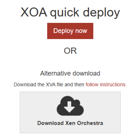
Navigate to https://xen-orchestra.com/#!/member/products and select the preferred deployment method.
3. For simplicity, this guide will use the online deployment method.
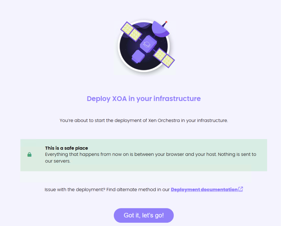
Your browser acts as a proxy for online deployment services, so you need to open this wizard on the PC that has access to the local network.
4. Open the Web console (XOA Lite) of the XCP-ng node on which you want to deploy XOA and accept the HTTPS certificate.
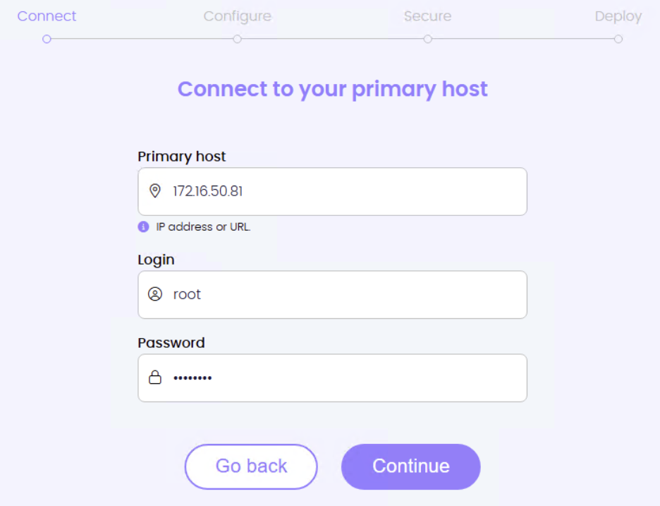
5. Specify the IP address of one of your XCP-ng nodes, login, and password. To learn primary-secondary meaning in XCP-ng clustering, read more here: https://docs.xcp-ng.org/management/ha/
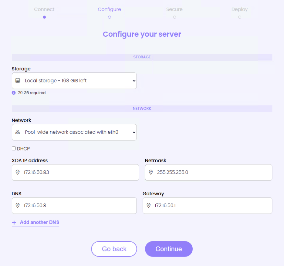
6. Select local storage (for example, BOSS card or OS RAID-1 disk) where XOA will be installed, and which network it should use.
7. Uncheck the DHCP box if you want a static IP address for the XOA appliance.
8. Specify login credentials, password, and SSH access to the XOA appliance.

9. XOA Appliance will begin its deployment. Make sure to keep the tab open until deployment is complete.
10. Once deployed, click Access XOA and proceed to log into your freshly deployed XOA.
11. Navigate to the XOA tab, click Updates, register your XOA appliance and install all the latest updates.
12. To add more servers to XOA, navigate to Settings -> Servers. Specify label, IP address, and login information. Click Connect once filled.
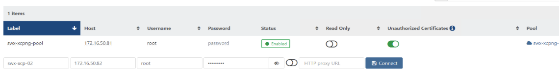
13. Click on the error message and accept the self-signed certificate.
14. Navigate to Home -> Pools, and there you will see individual pools, one per added host to XOA. Select one with XOA installed and click the Add Host button on the right-hand side.
15. Select recently added host(s) from the drop-down menu.
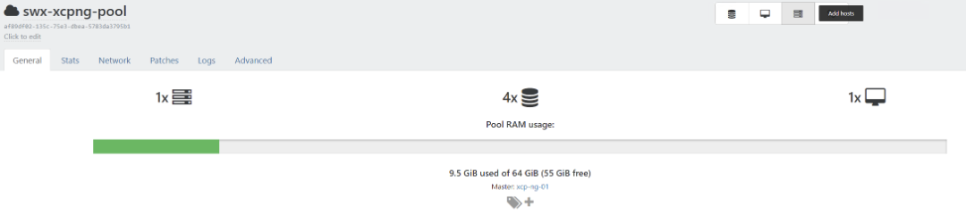
16. Click on the Pool name at the top and name it as you wish to call your cluster.
![]()
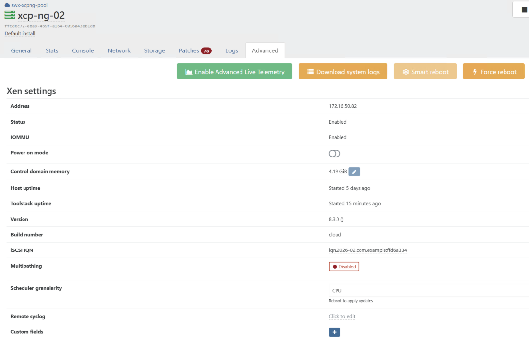
17. Now, multipath needs to be configured on all hosts before proceeding to StarWind configuration. To do so, navigate to Home -> Hosts and select the recently added node.
18. Navigate to the Advanced tab within host information and click on the Disabled button to enable Multipath.
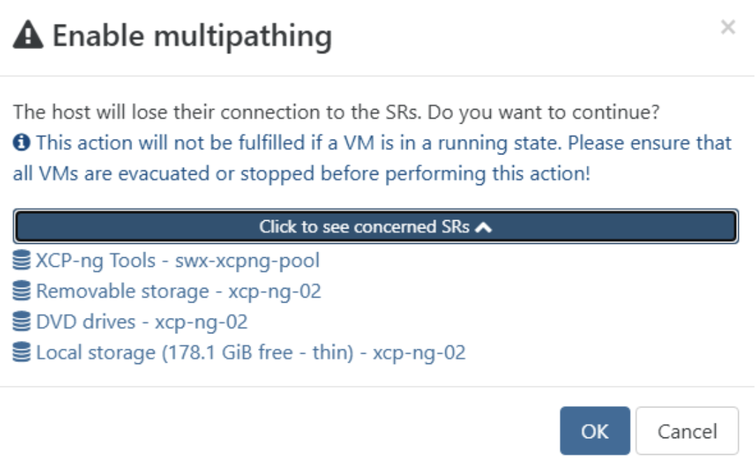
19. You will be prompted with a warning message concerning the existing storage repositories. Since the recently added node(s) don’t host the XOA appliance, you can click OK to continue.
NOTE: if you have VMs deployed on these nodes, you need to either migrate them to other node(s) or power them off before doing this operation.
20. Repeat steps on other recently added nodes before proceeding to the Master node.
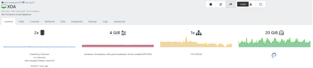
21. Since Master nodes are running the XOA appliance, to enable multipath on Master nodes, you first need to migrate the XOA appliance to a different node within a Pool. Navigate to Home -> VMs and click on XOA VM.
22. Click Migrate in the top right corner.
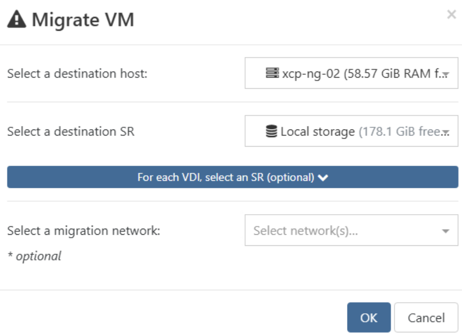
23. Specify the destination host and the local SR and click OK. You can check the progress in Tasks tab.
24. Once migration is complete, navigate to Home -> Hosts, then select the Master node to complete enabling Multipath.
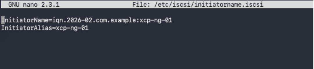
25. Additionally, in the Advanced settings of each host in a pool, you can change the iSCSI Initiator IQNs from automatically generated to what you prefer. Alternatively, you can also do it by changing the iSCSI configuration file. /etc/iscsi/initiatorname.iscsi to set the initiator name.
26. To prepare networking for StarWind HCI installation, navigate to Home -> Hosts and select the first node in the list.
27. Configure network interfaces on each node to make sure that Synchronization and iSCSI/StarWind heartbeat interfaces are in different subnets and connected according to the network diagram above. In this document, 172.16.10.x subnet is used for iSCSI/StarWind heartbeat traffic, while 172.16.20.x subnet is used for the Synchronization traffic. Navigate to Home -> Hosts, select the first node, and go to the Network tab.
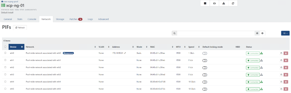
28. Identify networks that you want to use for StarWind traffic and iSCSI. Click None in the Mode column on the network that you want to use as iSCSI/StarWind heartbeat and select Static. You will be prompted with a wizard for specifying the IP address. This IP will be used by the Initiator to connect iSCSI storage presented by the VM.
29. Navigate to Home -> Pools -> Select Pool -> Network. Here you can rename network interfaces and set the MTU size to 9000.
NOTE: Setting MTU to 9000 bytes on some physical adapters (like Intel Ethernet Network Adapter X710, Broadcom network adapters, etc.) might cause stability and performance issues depending on the installed network driver. To avoid them, use 1500 bytes MTU size or install the stable version of the driver.
NOTE: If MTU is changed on the PIFs to 9000, please make sure that it’s changed on the corresponding adapters. Ping the IP address of the partner node using the command: ping -M do -s 8000 172.16.10.254 via SSH or Console within XenOrchestra.
30. Repeat step 27 for all network adapters. which will be used for Synchronization and ISCSI/StarWind heartbeat traffic.
31. Edit /etc/iscsi/iscsid.conf setting the following parameters:
node.startup = automatic
node.session.timeo.replacement_timeout = 15
node.session.scan = auto
32. Edit /etc/multipath/conf.d/custom.conf adding the following content:
devices{
	device{
		vendor "STARWIND"
		product "STARWIND*"
		path_grouping_policy multibus
		path_checker "tur"
		failback immediate
		path_selector "round-robin 0"
		rr_min_io 3
		rr_weight uniform
		hardware_handler "1 alua"
	}
}
NOTE: It is recommended to reboot hosts after applying the custom multipath config.
33. Repeat steps on all XCP-ng hosts.
Deploying StarWind Virtual SAN CVM
1. Download StarWind VSAN CVM OVA: VSAN by StarWind: Overview
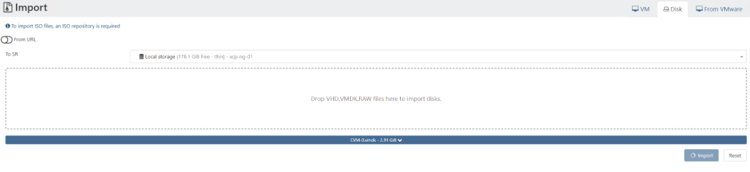
2. Extract the VM CVM-0.vmdk file from the downloaded archive.
3. Navigate to Import -> Disk. Select Pool and local storage SR. Upload CVM-0.vmdk file to the XOA. Repeat for all other host(s) local storage. Alternatively, you can use an ISO repository and an ISO image of StarWind VSAN CVM.
NOTE: VMDK files will be converted to VHD format.
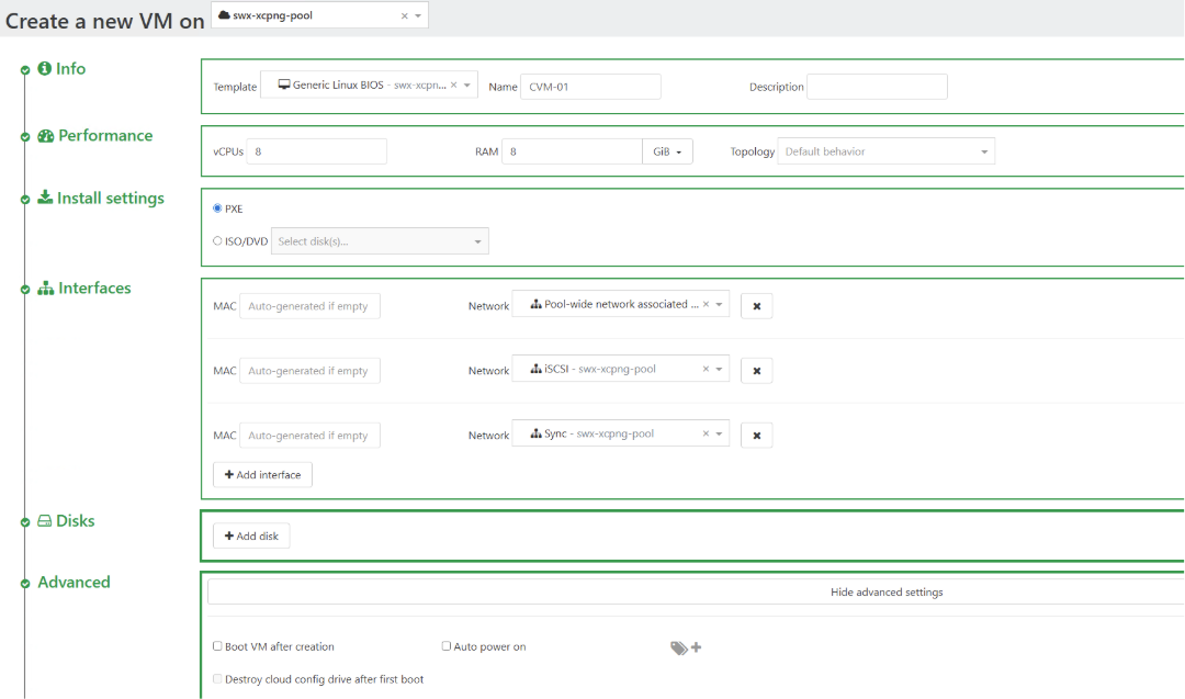
4. Navigate to Home and click +VM in the top right corner.
5. Select Pool, Select Generic Linux BIOS Template, Name VM, Assign 8 vCPU (recommended) and at least 8 GB of RAM (16 GB recommended), Select PXE install settings, add 3 networks (management network, iSCSI, and Sync), and remove disk created by the template. In advanced settings uncheck Boot VM after creation and click Create.
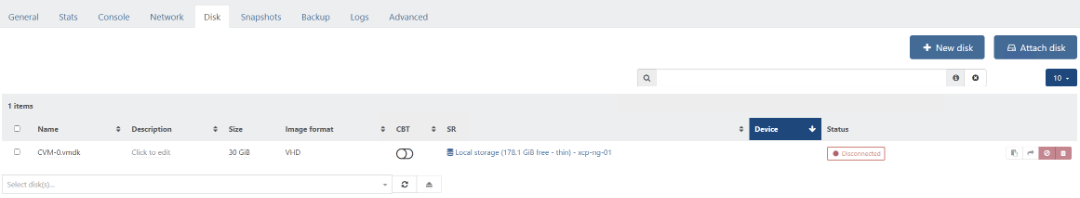
6. You will be redirected to the created VM. Navigate to disk, click Attach disk, and proceed to attach the recently imported disk.
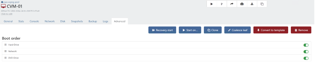
7. Navigate to the Advanced tab. Reorder Boot order by dragging the hard drive to the top and clicking Save.
8. In the Advanced tab, change the NIC type to Intel e1000 and click Save.
![]()
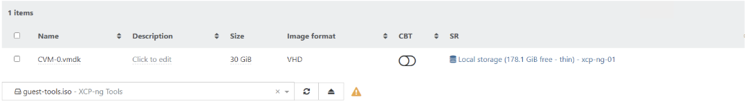
9. Navigate to Disk and select guest-tools.iso under primary virtual disk.
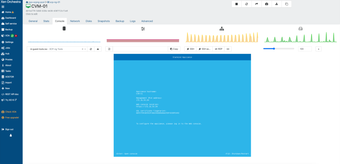
10. Power on the VM and navigate to Console.
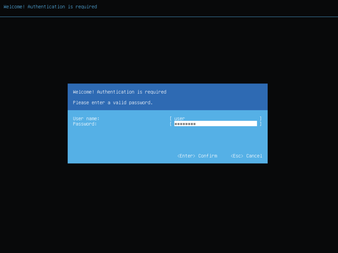
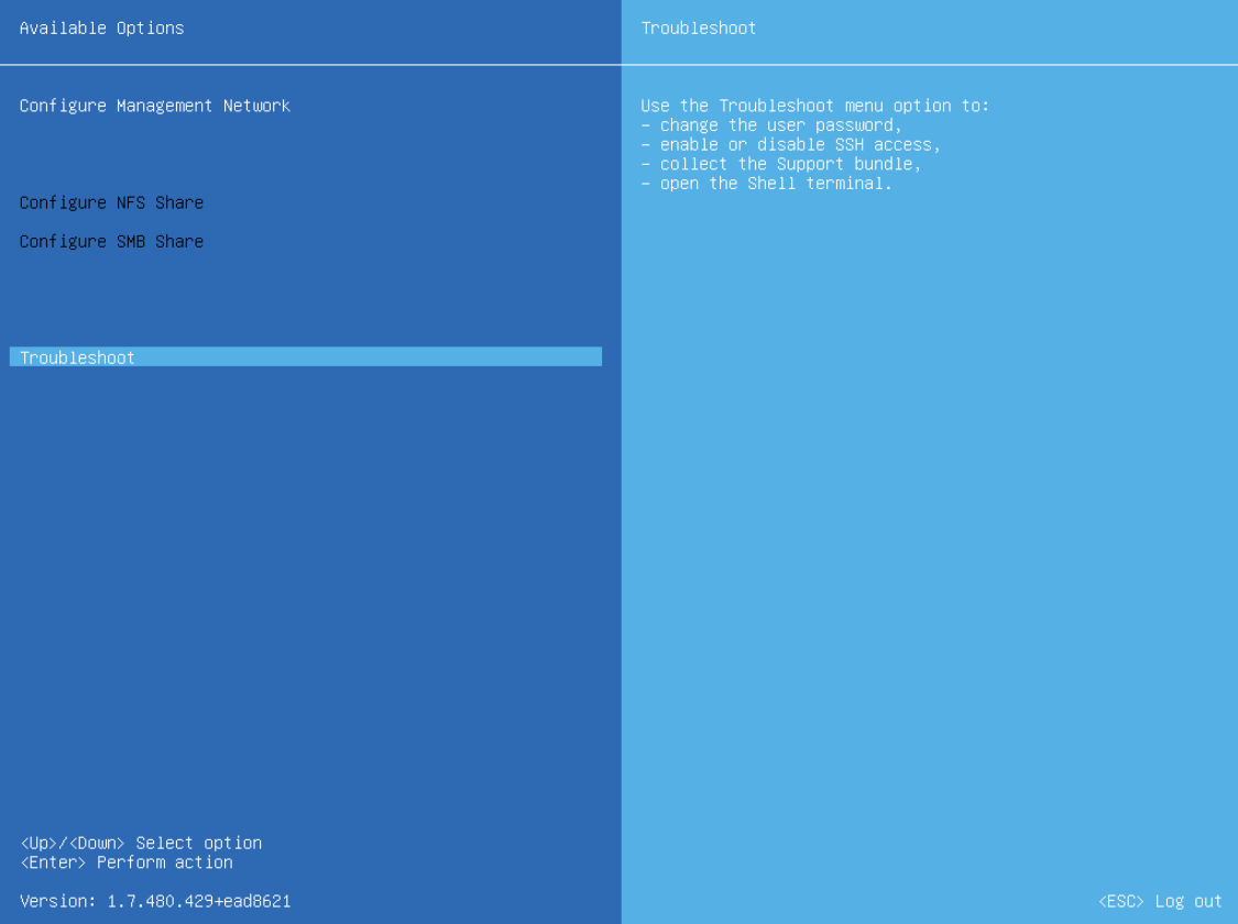
11. Once VM completes boot, press Enter to open the TUI console. Use the following credentials: user/rds123RDS.
12. Navigate to Troubleshoot and select Open Shell Terminal.
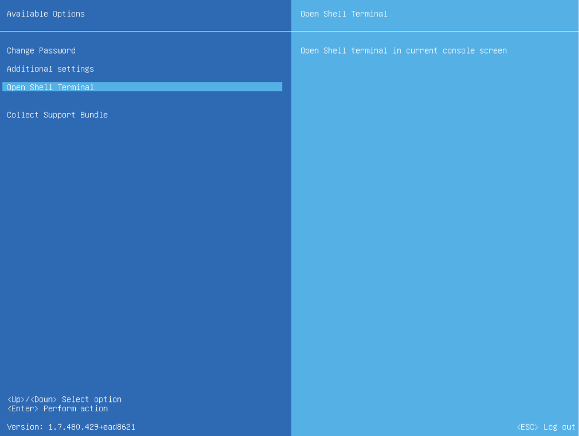
13. Inside the terminal, perform the following actions:
sudo mount /dev/cdrom /mnt
sudo bash /mnt/Linux/install.sh
sudo umount /dev/cdrom
This will install and enable XCP-ng guest tools
14. Shutdown Virtual Machine.
15. Navigate to the Disks tab and remove guest-tools.iso.
16. Repeat all the steps from this section on other XCP-ng hosts.
Attaching storage to StarWind Virtual SAN CVM
Please follow the steps below to attach the desired storage type to the CVM.
IMPORTANT NOTE: StarWind VSAN on XCP-ng only supports PCI-E pass-through.
Attaching PCIe device to StarWind Virtual SAN CVM
1. Shutdown StarWind VSAN CVM.
2. Navigate to Home -> Hosts, select the host, and open the Advanced tab.
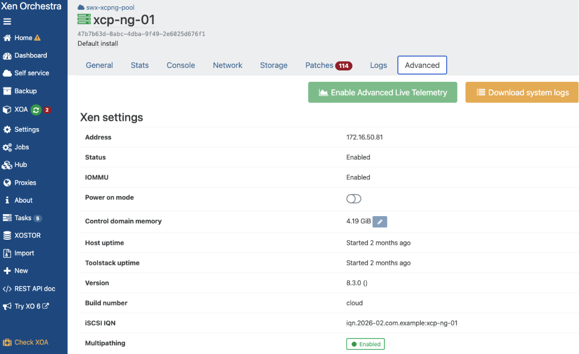
3. Scroll down to PCI devices and toggle Passthrough enabled for the RAID controller or NVMe devices you want to use for StarWind HA.
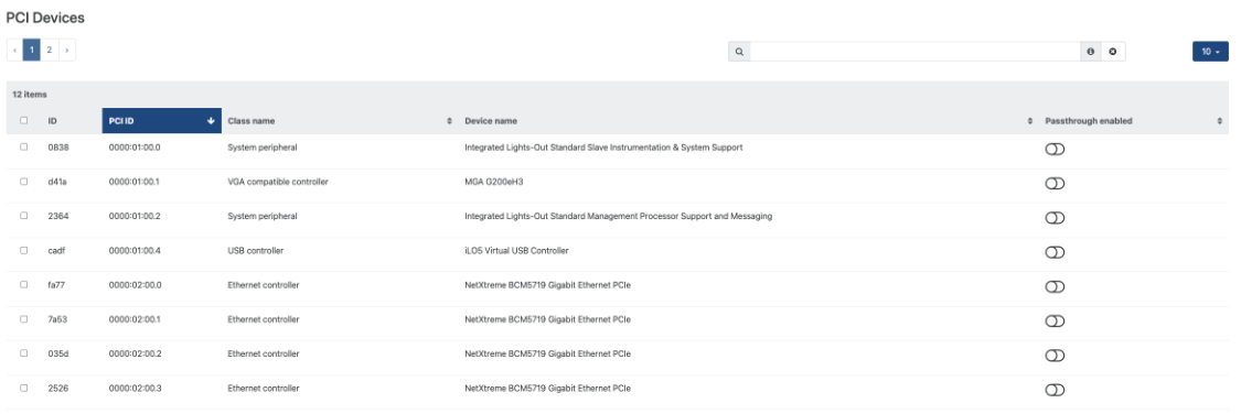
NOTE: this action will reboot the host in order to enable PCI-E passthrough for your VMs. Make sure you don’t have VMs running. You can also migrate XOA appliance between local storages for this
4. Navigate to StarWind VM and go to Advanced tab.
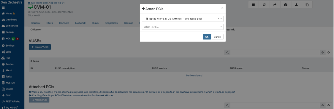
5. Scroll down to the Attach PCIs section. Click the Attach PCIs button. In the wizard, select which PCI-E device to attach and click OK.
6. Repeat steps 1-5 on all nodes for all PCI-E devices you want to attach to StarWind CVM.
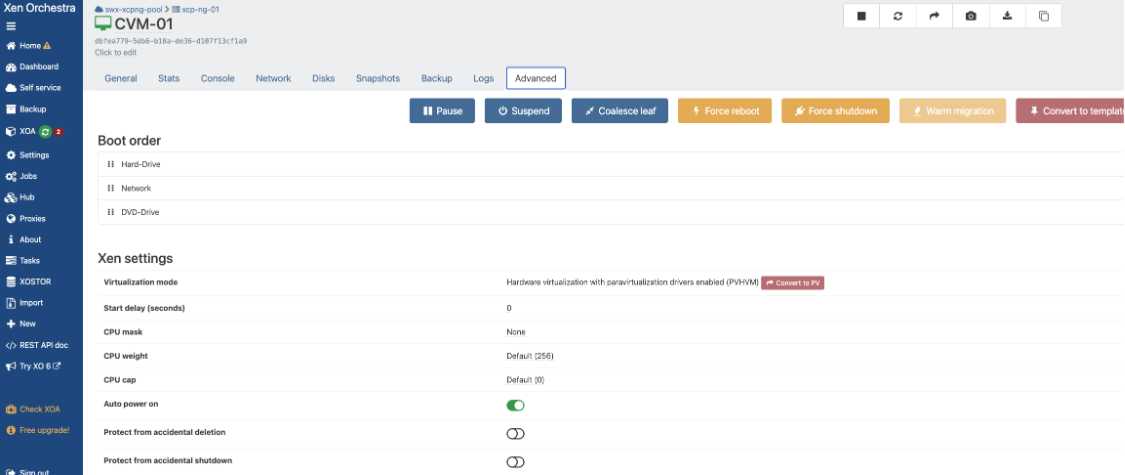
7. Navigate to the Advanced tab and enable Auto power on for StarWind VSAN CVM on each host.
Initial Configuration Wizard
1. Start the StarWind Virtual SAN Controller Virtual Machine.
2. Launch the VM console to view the VM boot process and obtain the IPv4 address of the Management network interface.
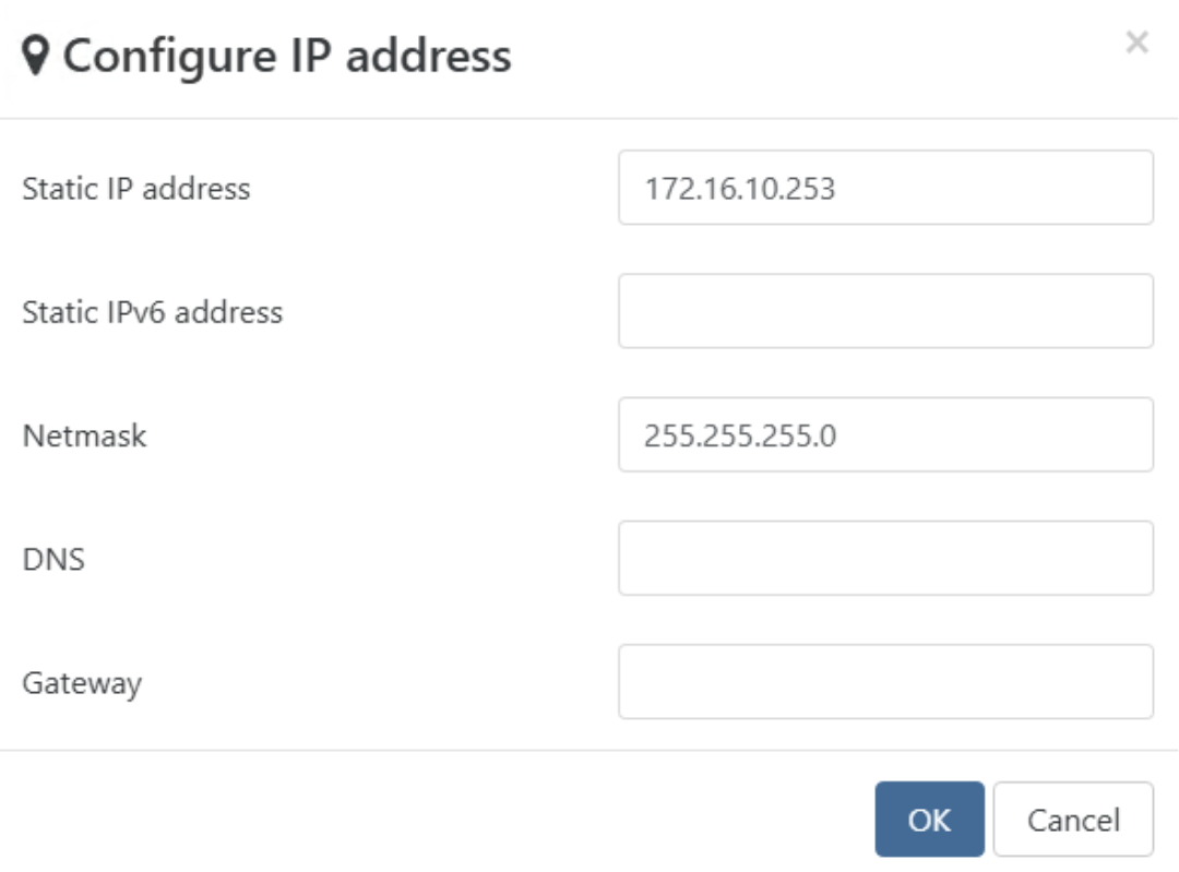
NOTE: If the VM does not acquire an IPv4 address from a DHCP server, use the Text-based User Interface (TUI) to set up the Management network manually. Use of static IP addresses is highly recommended.
Default credentials for TUI: user/rds123RDS
NOTE: Please make sure to change the default password
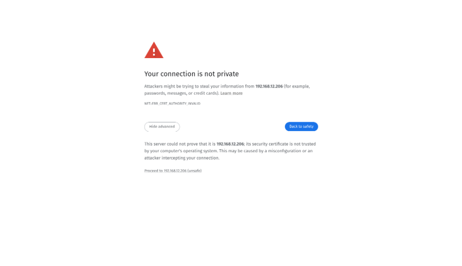
3. Using a web browser, open a new tab and enter the VM’s IPv4 address to access the StarWind VSAN Web Interface. On the Your connection is not private screen, click Advanced and then select Continue to…
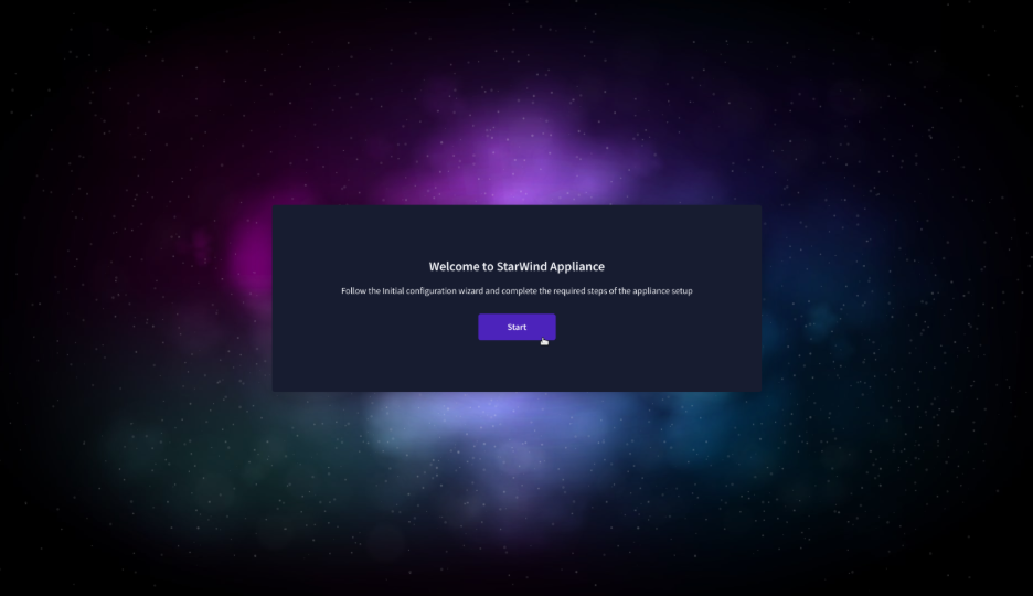
4. On the Welcome to StarWind Appliance screen, click Start to launch the Initial Configuration Wizard.
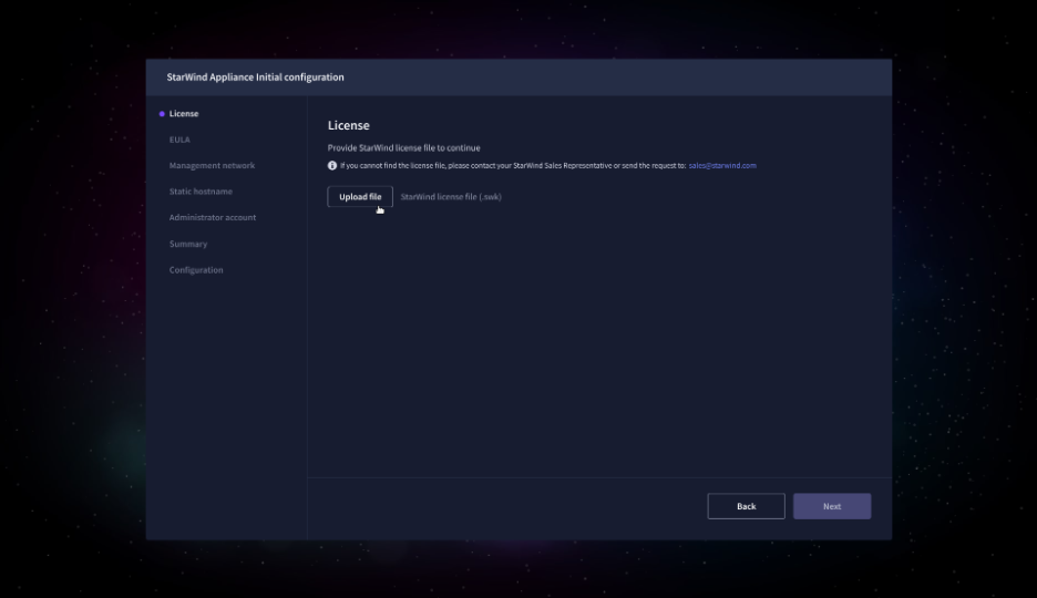
5. On the License step, upload the StarWind Virtual SAN license file.
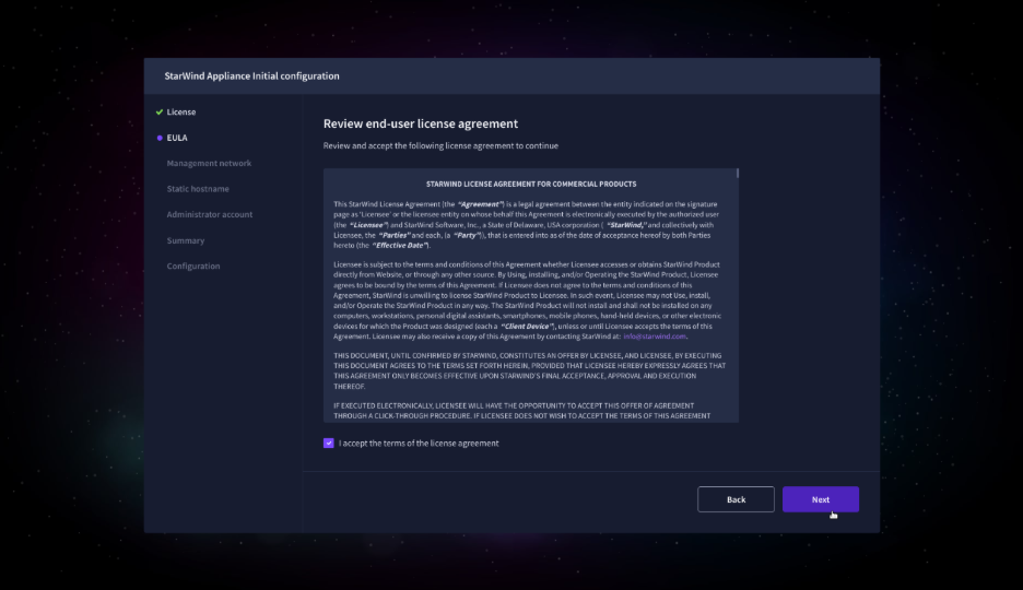
6. On the EULA step, read and accept the End User License Agreement to continue.
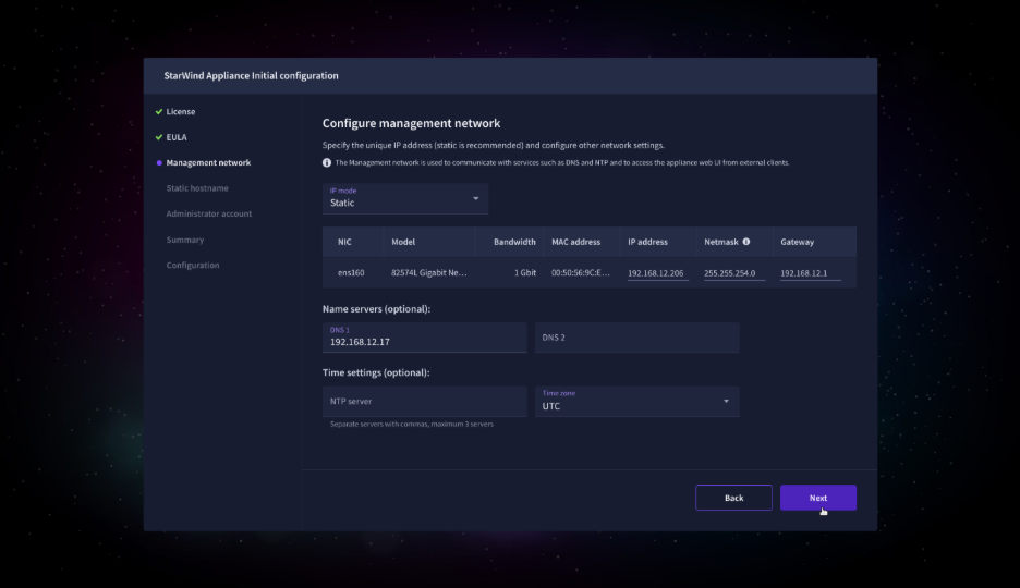
7. On the Management network step, review or edit the network settings and click Next.
IMPORTANT: The use of Static IP mode is highly recommended.
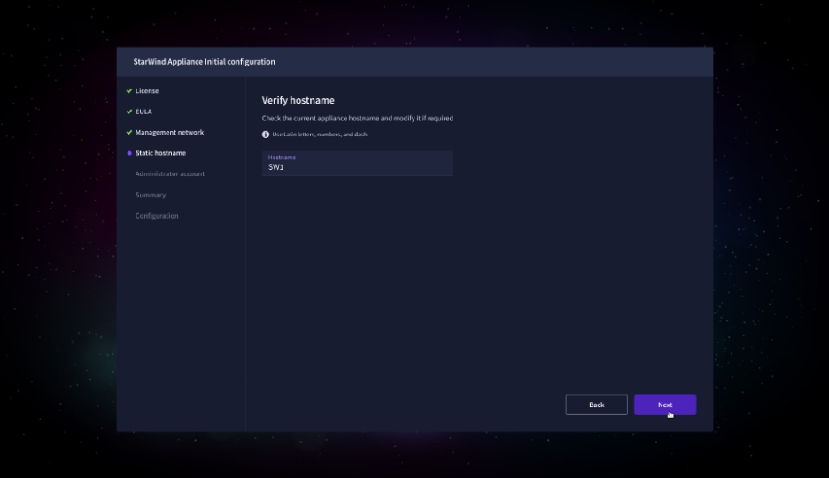
8. On the Static hostname, specify the hostname for the virtual machine and click Next.
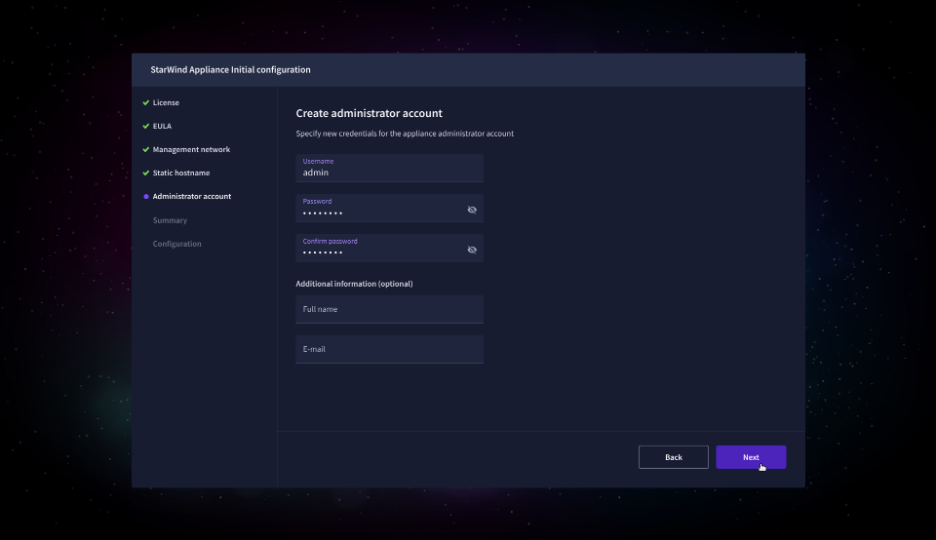
9. On the Administrator account step, specify the credentials for the new StarWind Virtual SAN administrator account and click Next.
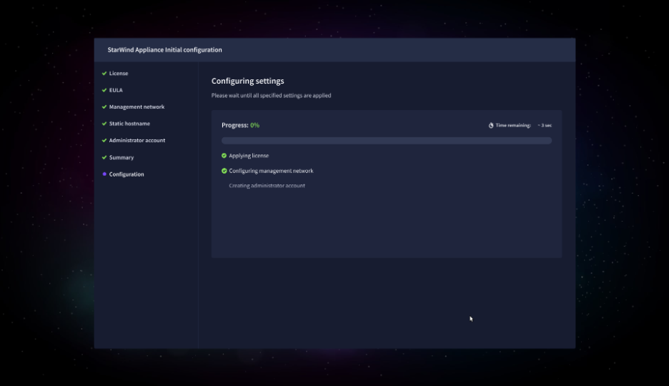
10. Wait until the Initial Configuration Wizard configures StarWind Virtual SAN for you.
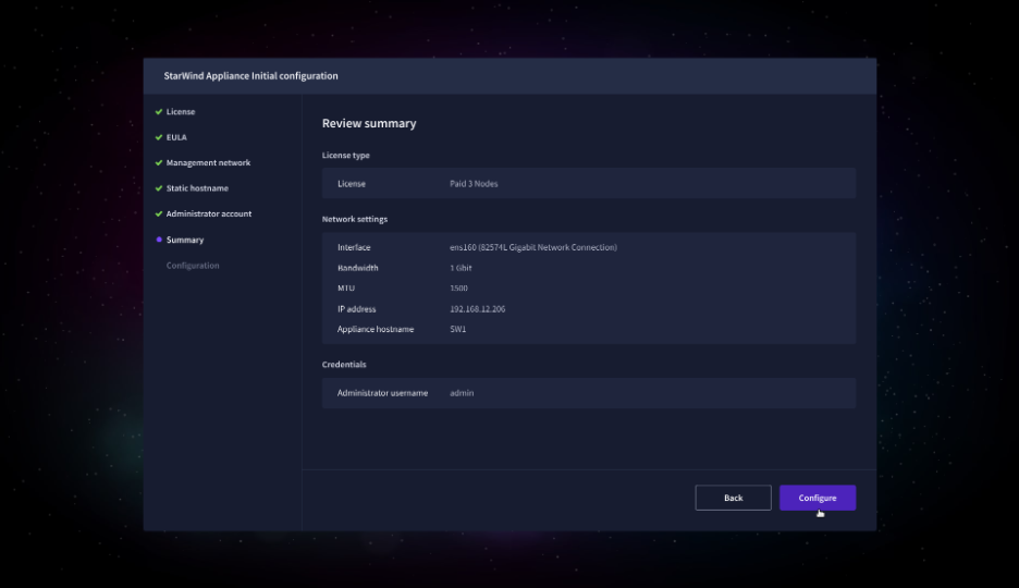
11. Please standby until the Initial Configuration Wizard configures StarWind VSAN for you.
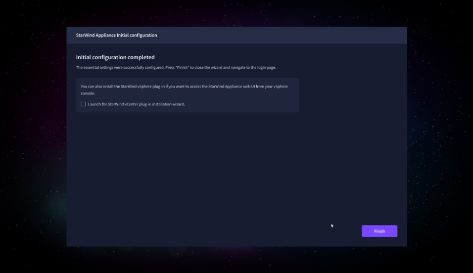
12. After the configuration process is completed, uncheck the checkbox to skip vCenter plug-in installation step, click Finish, and proceed to the Login page.
13. Repeat steps 1 through 12 on each XCP-ng host.
Add Appliance
To create replicated, highly available storage, add partner appliances that use the same StarWind Virtual SAN license key.
1. Navigate to the Appliances page and click Add to open the Add appliance wizard.
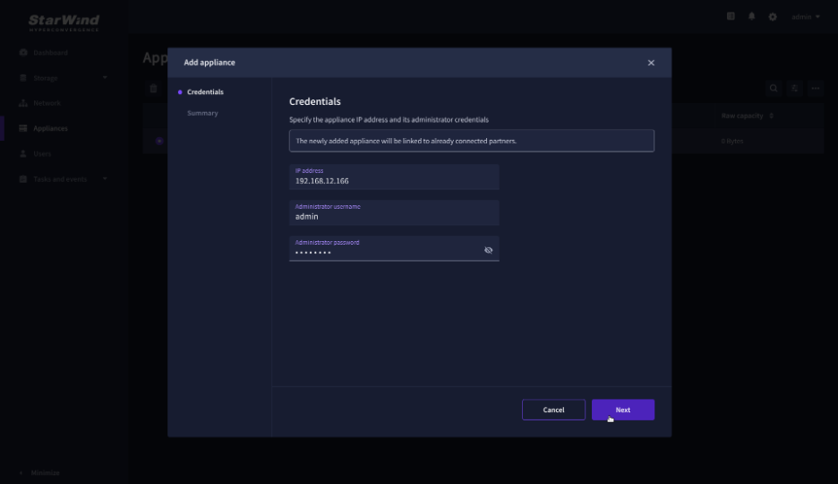
2. On the Credentials step, enter the IP address and credentials for the partner StarWind Virtual SAN appliance, then click Next.
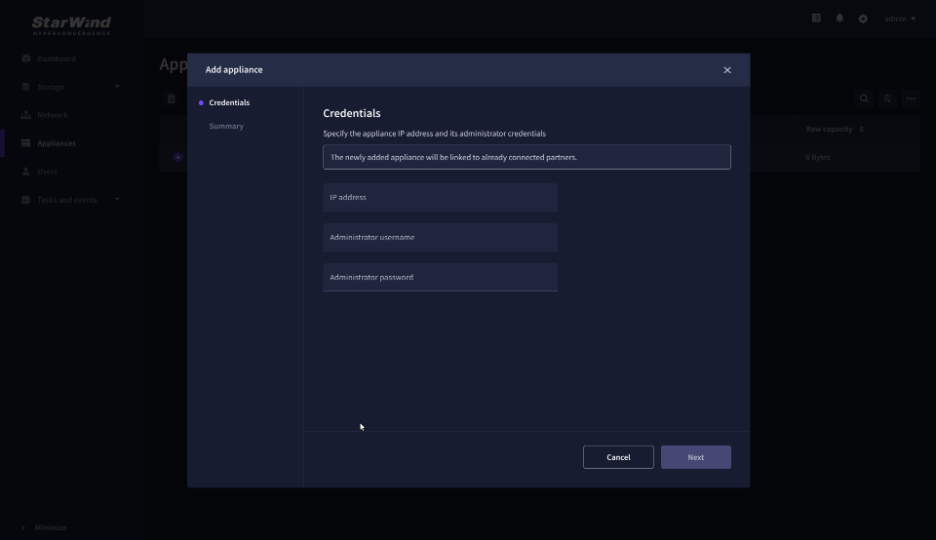
3. Provide credentials of partner appliance.
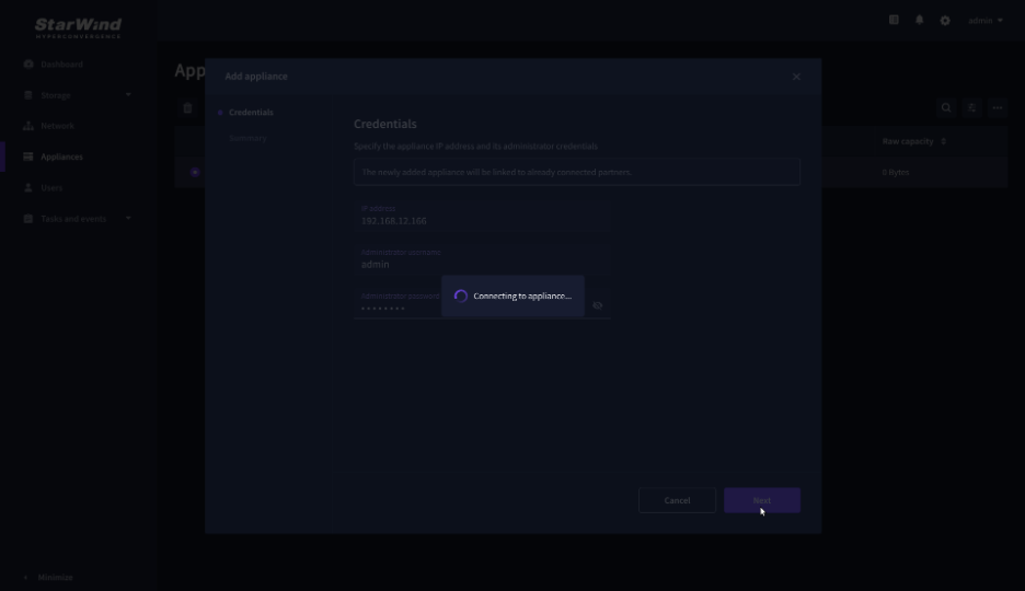
4. Wait for the connection to be established and the settings to be validated.
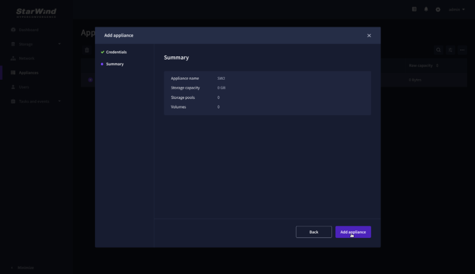
5. On the Summary step, review the properties of the partner appliance, then click Add Appliance.
Configure HA networking
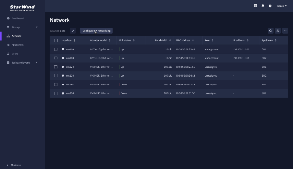
1. Navigate to the Network page and open Configure HA networking wizard.
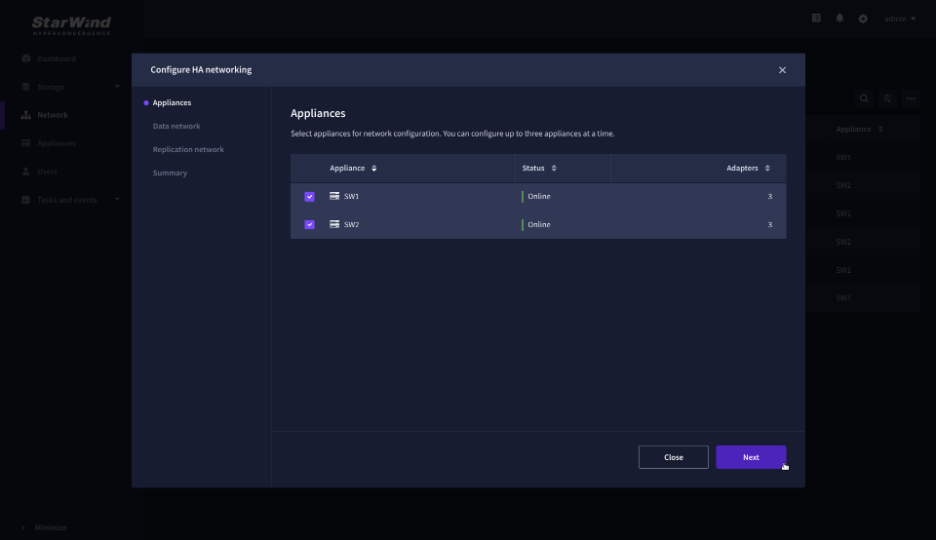
2. On the Appliances step, select either 2 partner appliances to configure two-way replication, or 3 appliances for three-way replication, then click Next.
NOTE: The number of appliances in the cluster is limited by your StarWind Virtual SAN license.
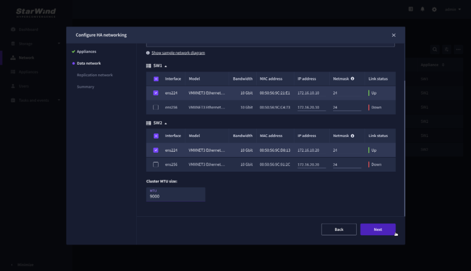
3. On the Data Network step, select the network interfaces designated to carry iSCSI or NVMe-oF storage traffic. Assign and configure at least one interface on each appliance (in our example: 172.16.10.10 and 172.16.10.20) with a static IP address in a unique network (subnet), specify the subnet mask and Cluster MTU size.
IMPORTANT: For a redundant, high-availability configuration, configure at least 2 network interfaces on each appliance. Ensure that the Data Network interfaces are interconnected between appliances through multiple direct links or via redundant switches.
4. Assign MTU value on all selected network adapters, e.g. 1500 or 9000 bytes. If you are using network switches with the selected Data Network adapters, ensure that they are configured with the same MTU size value. In case of MTU settings mismatch, stability and performance issues might occur on the whole setup.
NOTE: Setting MTU to 9000 bytes on some physical adapters (like Intel Ethernet Network Adapter X710, Broadcom network adapters, etc.) might cause stability and performance issues depending on the installed network driver. To avoid them, use 1500 bytes MTU size or install the stable version of the driver.
5. Once configured, click Next to validate network settings.
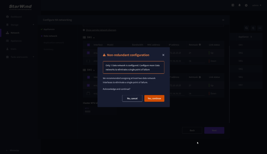
6. The warning might appear if a single data interface is configured. Click Yes, continue to proceed with the configuration.
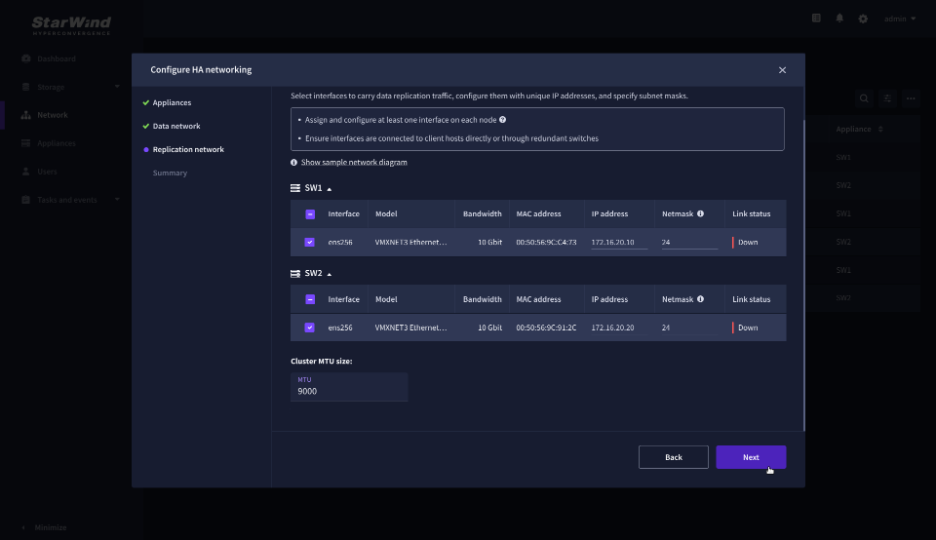
7. On the Replication Network step, select the network interfaces designated to carry the traffic for synchronous replication. Assign and configure at least one interface on each appliance with a static IP address in a unique network (subnet), specify the subnet mask and Cluster MTU size.
IMPORTANT: For a redundant, high-availability configuration, configure at least 2 network interfaces on each appliance. Ensure that the Replication Network interfaces are interconnected between appliances through multiple direct links or via redundant switches.
8. Assign MTU value on all selected network adapters, e.g. 1500 or 9000 bytes. If you are using network switches with the selected Replication Network adapters, ensure that they are configured with the same MTU size value. In case of MTU settings mismatch, stability and performance issues might occur on the whole setup.
NOTE: Setting MTU to 9000 bytes on some physical adapters (like Intel Ethernet Network Adapter X710, Broadcom network adapters, etc.) might cause stability and performance issues depending on the installed network driver. To avoid them, use 1500 bytes MTU size or install the stable version of the driver.
9. Once configured, click Next to validate network settings.
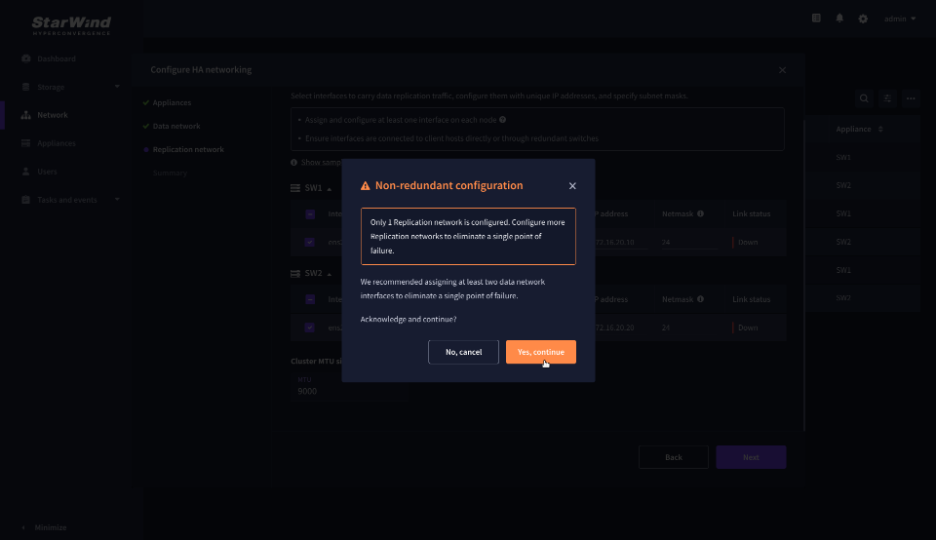
10. If only one Replication Network interface is configured on each partner appliance, a warning message will pop up. Click Yes, continue to acknowledge the warning and proceed.
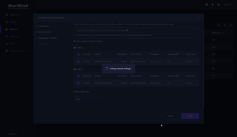
11. Wait for the configuration completion.
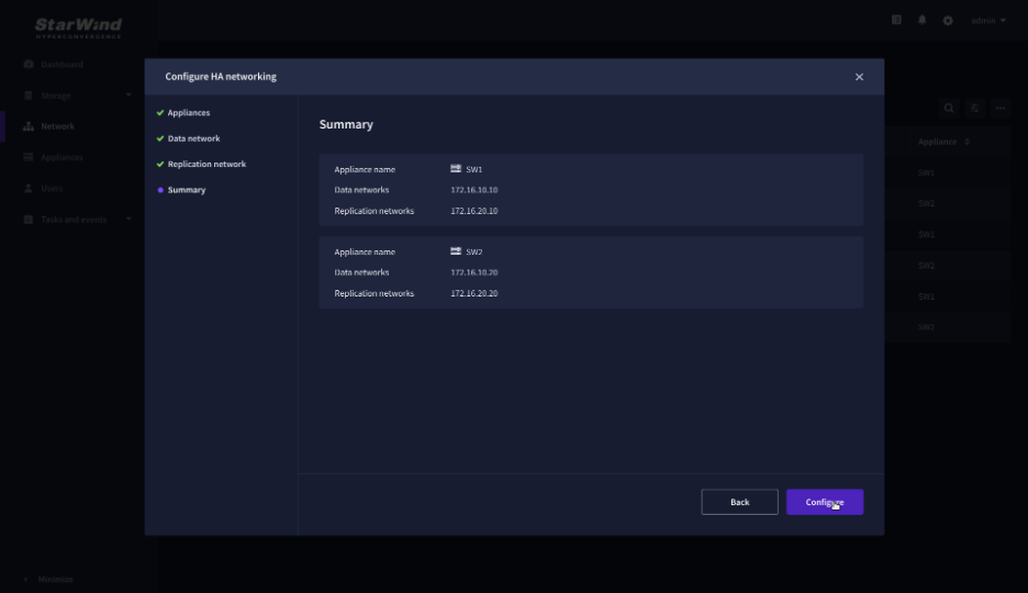
12. On the Summary step, review the specified network settings and click Configure to apply the changes.
Create Storage Pool
1. Navigate to the Storage pools page and click the + button to open the Create storage pool wizard .
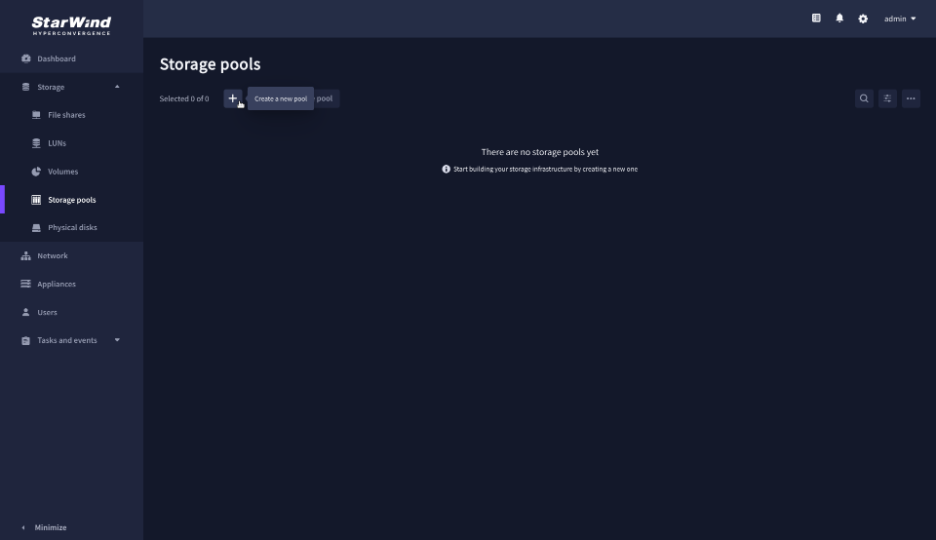
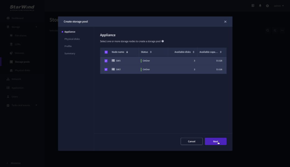
2. On the Appliance step, select partner appliances on which to create new storage pools, then click Next.
NOTE: Select 2 appliances for configuring storage pools if you are deploying a two-node cluster with two-way replication, or select 3 appliances for configuring a three-node cluster with a three-way mirror.
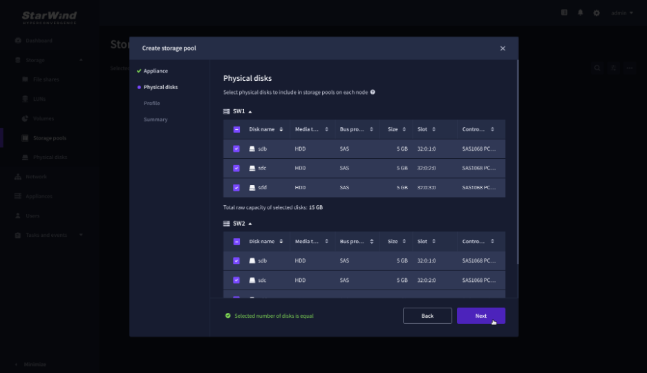
3. On the Physical disks step, select physical disks to be pooled on each node, then click Next.
IMPORTANT: Select an identical type and number of disks on each appliance to create storage pools with a uniform configuration.
4. On the Profile step, select one of the preconfigured storage profiles, or choose Manual to configure the storage pool manually based on your redundancy, capacity, and performance requirements, then click Next.
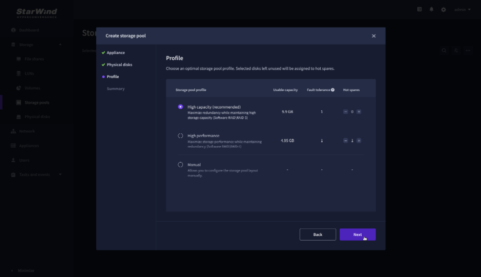
NOTE: Hardware RAID, Linux Software RAID, and ZFS storage pools are supported. To simplify the configuration of storage pools, preconfigured storage profiles are provided. These profiles recommend a pool type and layout based on the attached storage:
- High capacity – creates Linux Software RAID-5 to maximize storage capacity while maintaining redundancy.
- High performance – creates Linux Software RAID-10 to maximize storage performance while maintaining redundancy.
- Hardware RAID – configures a hardware RAID virtual disk as a storage pool. This option is available only if a hardware RAID controller is passed through to the StarWind Virtual SAN.
- Better redundancy – creates ZFS Striped RAID-Z2 (RAID 60) to maximize redundancy while maintaining high storage capacity.
- Manual – allows users to configure any storage pool type and layout with the attached storage.
5. On the Summary step, review the storage pool settings and click Create to configure new storage pools on the selected appliances.
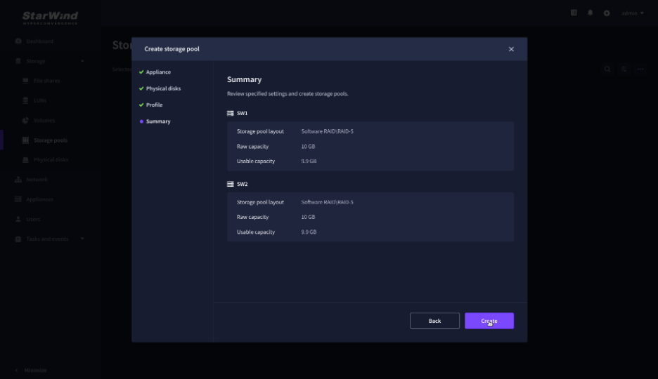
NOTE: The storage pool configuration may take some time, depending on the type of pooled storage and the total storage capacity. Once the pools are created, a notification will appear in the upper right corner of the Web UI.
IMPORTANT: In some cases, additional tweaks are required to optimize the storage performance of the disks added to the Controller Virtual Machine. Please follow the steps in this KB to change the scheduler type depending on the disks type: https://knowledgebase.starwindsoftware.com/guidance/starwind-vsan-for-vsphere-changing-linux-i-o-scheduler-to-optimize-storage-performance/
Create Volume
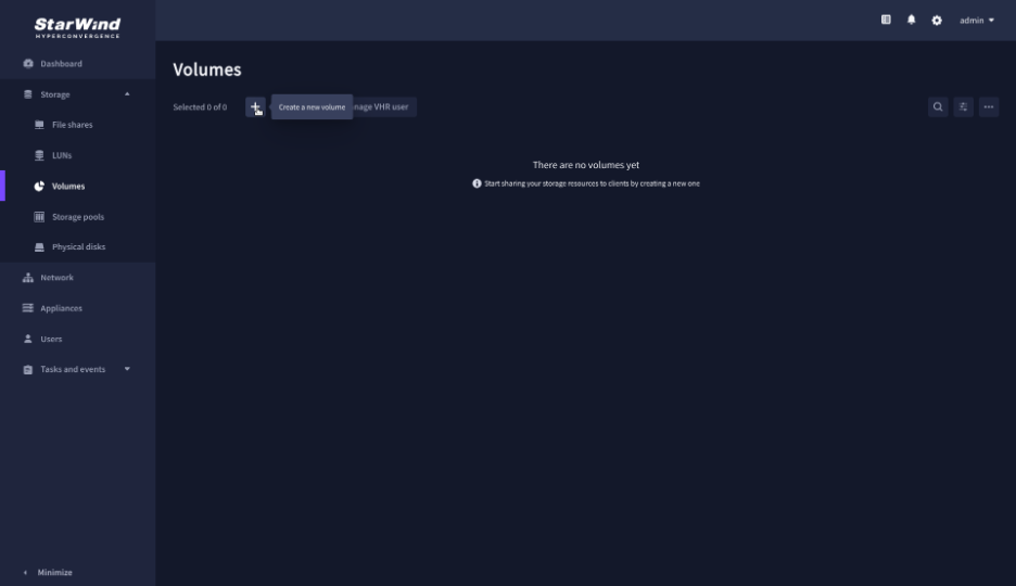
1. Navigate to the Volumes page and click the + button to open the Create volume wizard.
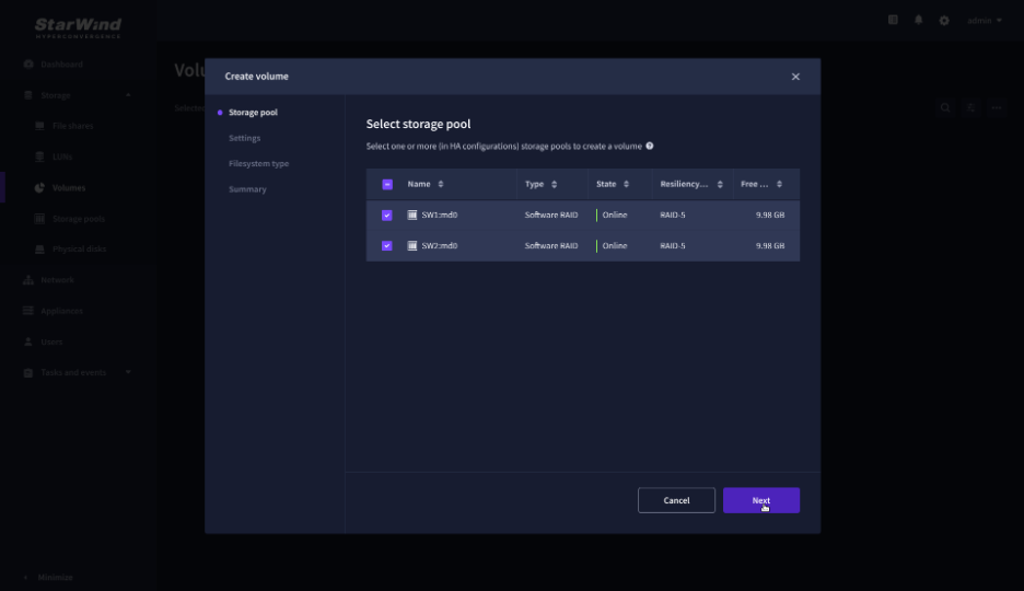
2. On the Storage pool step, select partner appliances on which to create new volumes, then click Next.
NOTE: Select 2 appliances for configuring volumes if you are deploying a two-node cluster with two-way replication, or select 3 appliances for configuring a three-node cluster with a three-way mirror.
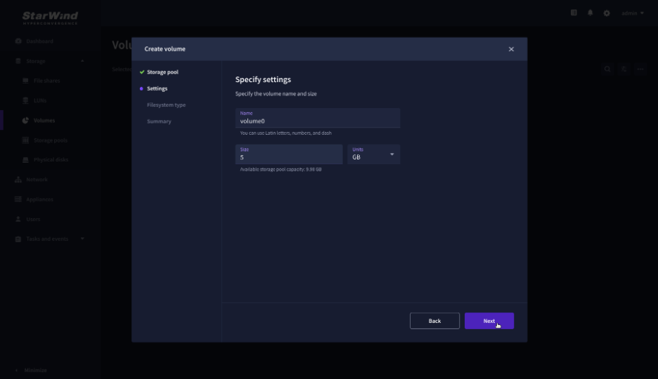
3. On the Settings step, specify the volume name and size, then click Next.
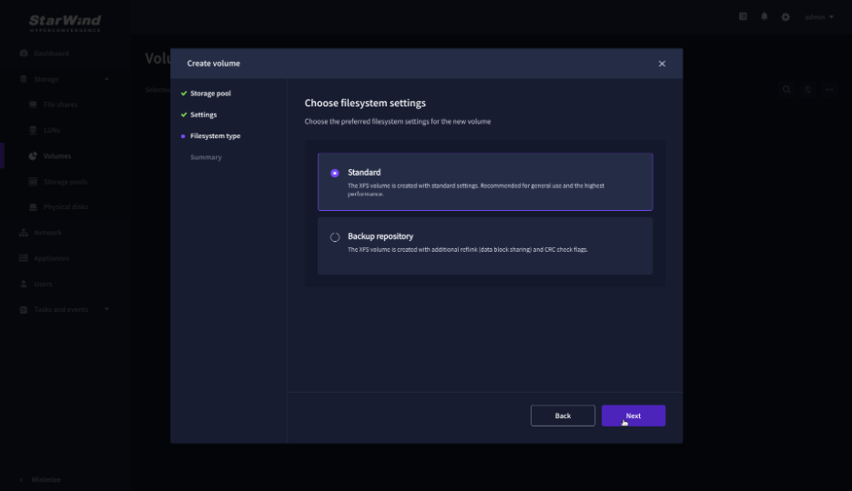
4. On the Filesystem type step, select Standard, then click Next.
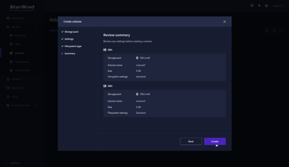
5. Review Summary and click the Create button to create the pool.
Create HA LUN using WebUI
This section describes how to create LUN in Web UI. This option is available for the setups with Commercial, Trial, and NFR licenses applied.
For setups with a Free license applied, the PowerShell script should be used to create the LUN – please follow the steps described in the section: Create StarWind HA LUNs using PowerShell.
1. Navigate to the LUNs page and click the + button to open the Create LUN wizard.

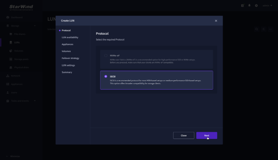
2. On the Protocols step, select the preferred storage protocol and click Next.
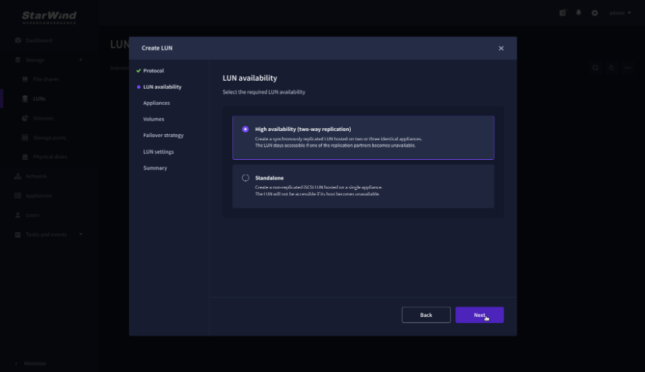
3. On the LUN availability step, select the High availability and click Next.
NOTE: The availability options for a LUN can be Standalone (without replication) or High Availability (with 2-way or 3-way replication), and are determined by the StarWind Virtual SAN license.
Below are the steps for creating a high-availability iSCSI LUN.
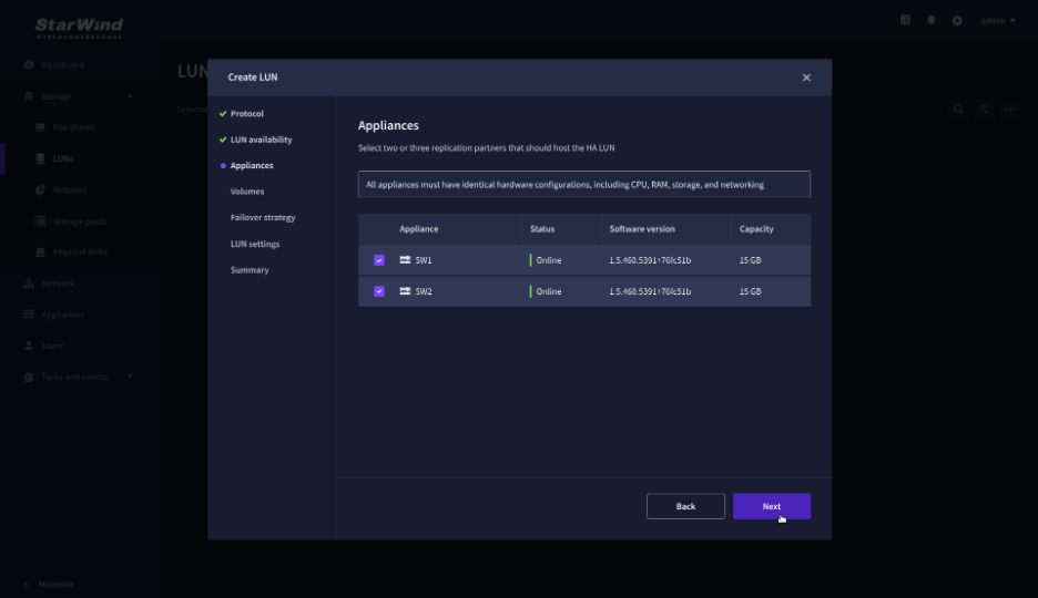
4. On the Appliances step, select partner appliances that will host new LUNs and click Next.
IMPORTANT: Selected partner appliances must have identical hardware configurations, including CPU, RAM, storage, and networking.
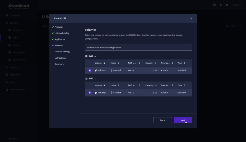
5. On the Volumes step, select the volumes for storing data on the partner appliances and click Next.
IMPORTANT: For optimal performance, the selected volumes must have identical underlying storage configurations.
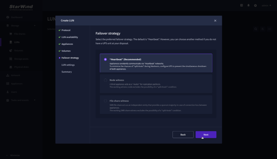
6. On the Failover strategy step, select the preferred failover strategy and click Next.
NOTE: The failover strategies for a LUN can be Heartbeat or Node Majority. In case of a 2-node setup and the Node Majority failover strategy, the Node witness (requires an additional third witness node), or the File share witness (requires an external file share) should be configured. These options are determined by StarWind Virtual SAN license and setup configuration. Below are the steps for configuring the Heartbeat failover strategy in a two-node cluster.
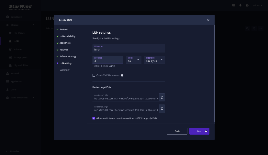
7. On the LUN settings step, specify the LUN name, size, block size, then click Next.
NOTE: For high-availability configurations, ensure that MPIO checkbox is selected.
NOTE: For XCP-ng configuration, ensure that the 512 bytes block size is selected.
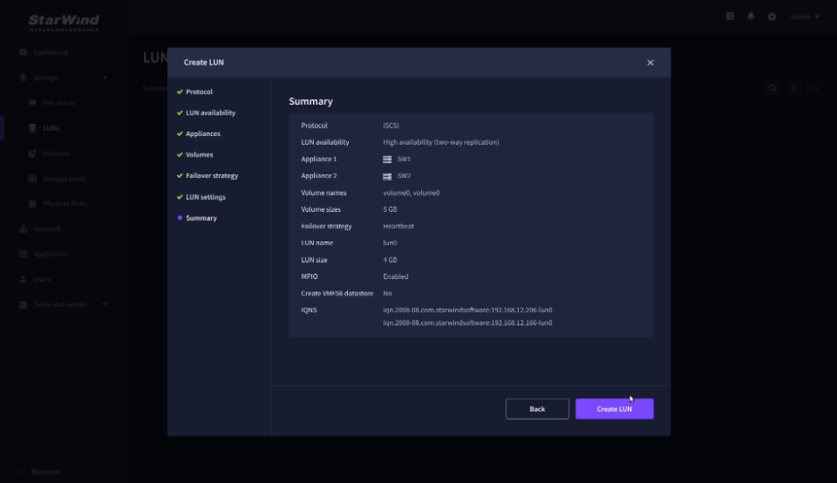
8. On the Summary step, review the LUN settings and click Create to configure new LUNs on the selected volumes.
Adding StarWind Storage to XCP-ng
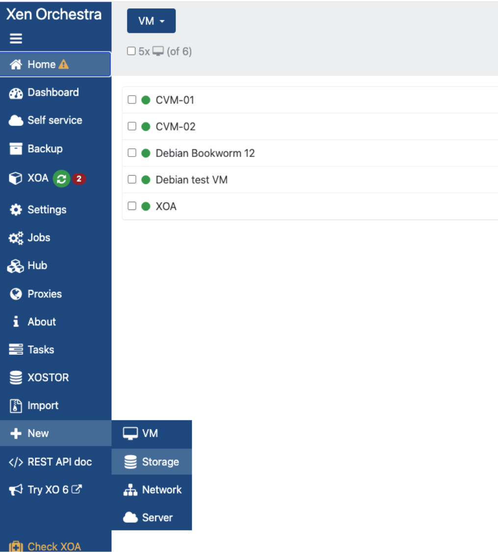
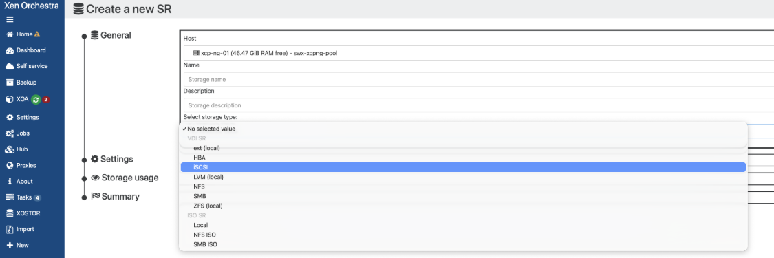
There are several ways to add StarWind storage to an XCP-ng cluster. One of which is via UI. Navigate to New and select Storage. Select one of the nodes within your pool and select iSCSI in Storage type.
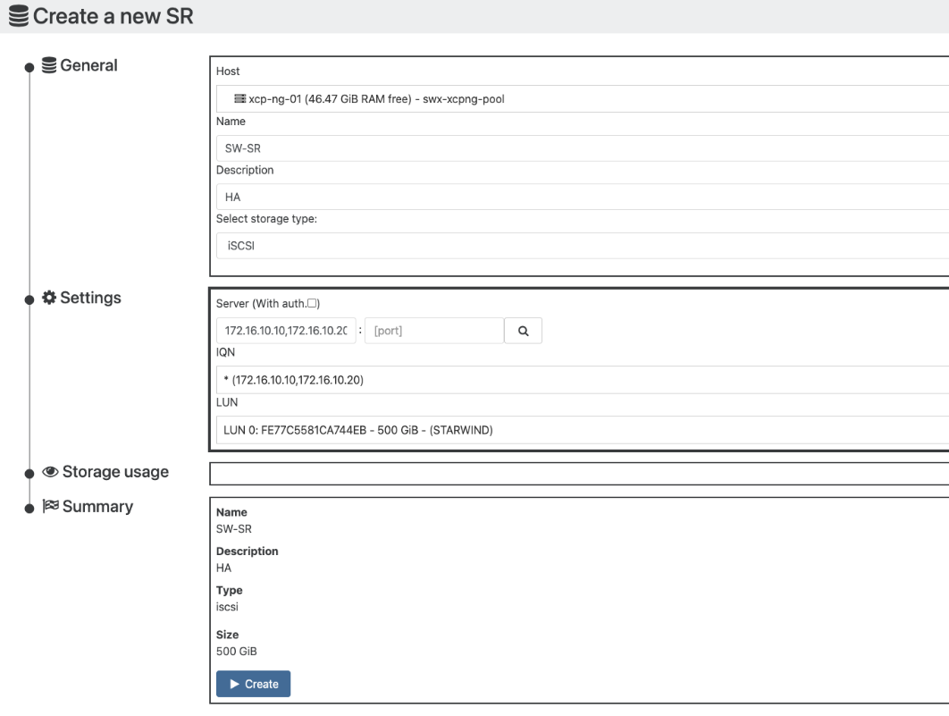
Enter CVMs iSCSI IP addresses with a comma between them, let XCP-ng scan the storage and click Create.
NOTE: Please make sure that storage is discovered and connected via all iSCSI interfaces from each CVM with an HA device created.
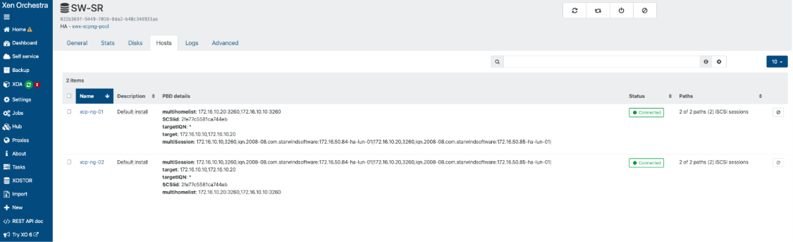
Once StarWind HA is presented as a Storage Repository to your pool, double-check iSCSI multipath configuration by navigating to Home -> Storage -> Select created SR -> Hosts. Find below the example of paths for the Storage Repository connected to a 2-node XCP-ng cluster.
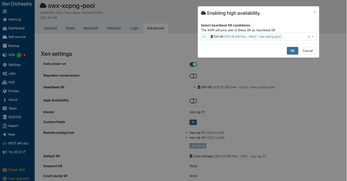
Navigate to Home -> Pools, select your pool, go to the Advanced tab, and enable High Availability. Select StarWind HA as heartbeat SR and click OK.
Now, you can deploy your VMs on top of StarWind HA. To achieve HA for XOA appliance, move it to one of your StarWind HA devices.
Conclusion
Following this guide, an XCP-ng cluster was deployed and configured with StarWind Virtual SAN (VSAN) running in a CVM on each host. As a result, a StarWind highly available storage was created, connected to all XCP-ng clustered nodes to store virtual machines on a highly available Storage Repository.
