

Configuration Guide for Microsoft Windows Server, VSAN Deployed as a Controller Virtual Machine (CVM)
- November 14, 2025
- 66 min read
- Download as PDF
Annotation
Relevant products
This guide applies to StarWind Virtual SAN and StarWind Virtual SAN Free, specifically Controller Virtual Machine (CVM) version 20231016 and later.
For older versions of StarWind Virtual SAN (OVF Version 20230901 and earlier), please refer to this configuration guide:
Purpose
This document outlines how to configure a Microsoft Hyper-V Failover Cluster using StarWind Virtual SAN (VSAN), with VSAN running as a Controller Virtual Machine (CVM). The guide includes steps to prepare Hyper-V hosts for clustering, configure physical and virtual networking, and set up the Virtual SAN Controller Virtual Machine.
For more information about StarWind VSAN architecture and available installation options, please refer to the:
StarWind Virtual (VSAN) Getting Started Guide.
Audience
This technical guide is intended for storage and virtualization architects, system administrators, and partners designing virtualized environments using StarWind Virtual SAN (VSAN).
Expected result
Following this guide will result in a fully configured, highly available Windows Failover Cluster with virtual machine shared storage provided by StarWind VSAN.
NOTE: This guide applies to clusters with 2, 3, or more nodes. Be sure to follow the notes within each configuration step to ensure you perform the actions appropriate for your specific cluster size.
Multi-Node Cluster Configuration
StarWind Virtual SAN (VSAN) provides a flexible architecture that supports clusters of varying sizes, depending on the chosen hypervisor and deployment needs. The maximum size of a cluster is typically determined by the hypervisor vendor’s limitations. For instance, VMware and Hyper-V impose specific constraints on the number of nodes that can be part of a single
cluster. However, from StarWind’s perspective, there are no inherent restrictions on the number of nodes in a cluster.
While StarWind VSAN imposes no limits on the cluster’s overall size, the synchronization for highly- available (HA) devices is limited to 2 or 3 nodes. To utilize StarWind VSAN effectively in larger clusters, devices can be replicated with an offset between nodes, in so-called GRID architecture. Replicating HA devices across different nodes with 2 or 3-way replica allows to ensure that all nodes in the cluster contribute to storage redundancy and failover capabilities. This approach maximizes also storage resource utilization, data redundancy and enhances the overall fault tolerance of the system.
To ensure optimal performance and fault tolerance, it is essential to establish resilient networking between cluster nodes. This involves:
- Redundant network links: Implementing multiple paths to avoid single points of failure.
- Sufficient bandwidth: Ensuring the network can handle synchronization traffic.
- Low latency: Minimizing delays to enhance HA replication efficiency.
Below is the conceptual diagram with StarWind VSAN deployment in a multi-node cluster.
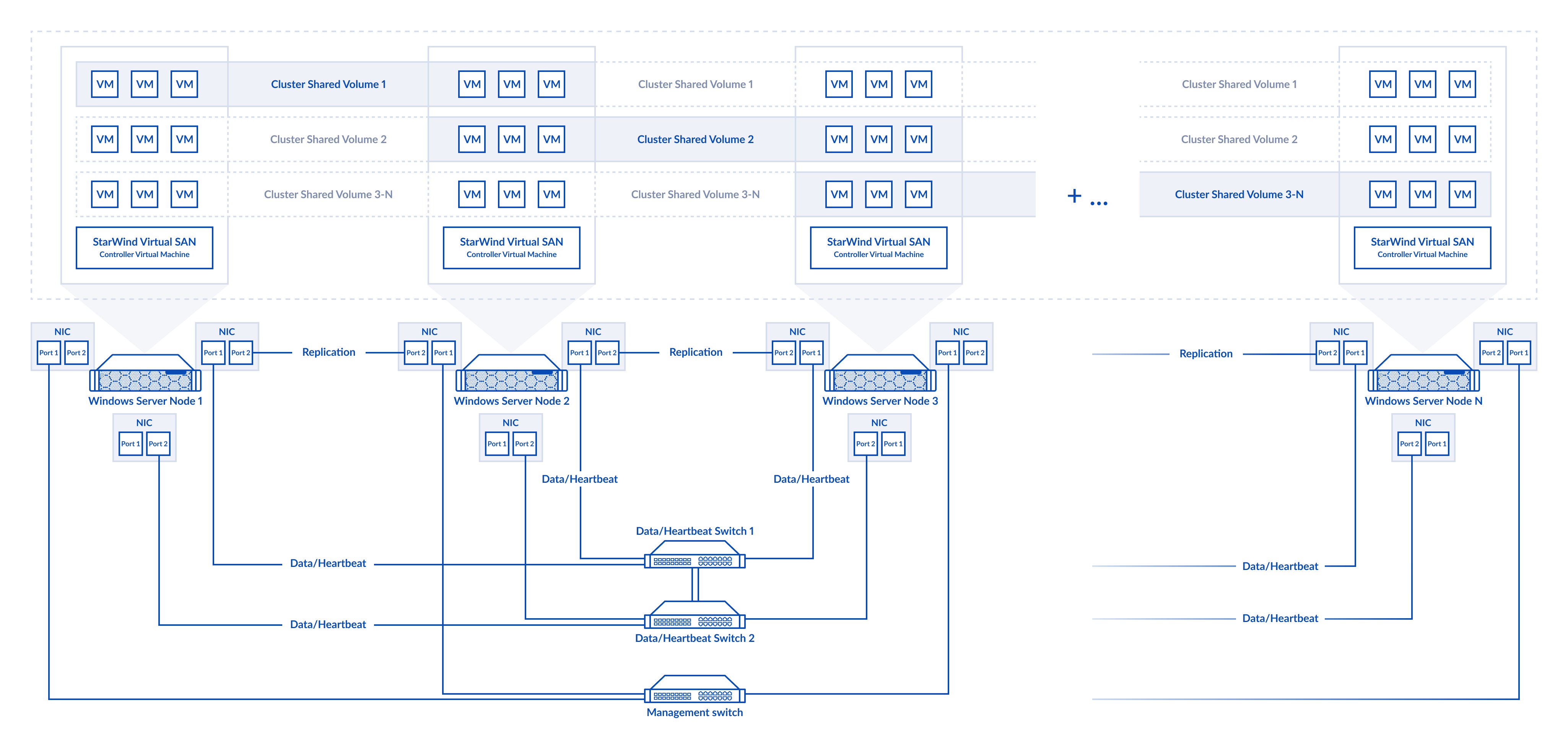
Figure 1. Multi-node cluster configuration
The links between the cluster nodes can be connected via network switches or directly (for example for the replication links). As it was mentioned already, StarWind devices can be replicated in a 2-way or 3-way replica with an offset between nodes and connected on all cluster nodes. Data and Replication channels should not be used over the same physical link to avoid potential performance issues.
For example, in 4-nodes cluster the 1st HA device is replicated between the 1st and 2nd nodes, the 2nd HA device – is between the 2nd and 3d nodes, the 3d HA device – between the 3d and 4th nodes and the 4th HA device – between the 4th and 1st nodes. The storage configuration could be different depending on the requirements.
Please do not hesitate to contact StarWind support to design the setup with multi-nodes.
2-Node Cluster Configuration
StarWind VSAN allows the creation of a minimalistic 2-node Microsoft Failover Cluster with shared storage while ensuring data redundancy and fault tolerance at the storage level.
To deploy a 2-node setup, both nodes must have identical hardware and meet the minimum StarWind VSAN system requirements, including supported OS, memory size, dedicated network interfaces, latency specifications, and minimum connection speed.
In a StarWind VSAN-based hyperconverged setup the compute, storage, and networking are integrated into a single solution. Shared storage, managed by StarWind VSAN running as a Controller Virtual Machine (CVM), is replicated between the same hosts where the StarWind CVM itself, the cluster, and the clustered VMs reside. StarWind VSAN CVM (can be installed on the local storage where the OS is installed) should be deployed on each Windows Server to configure the cluster. Local storage, such as physical disks, NVMe, or RAID arrays on each server intended for data, should be added to the StarWind Controller Virtual Machine (CVM). The StarWind CVM manages virtual disks replicated with the same StarWind CVM on another server, creating a shared storage pool. This highly available (HA) storage is connected to each server and used as cluster storage. Data replication in active-active mode between StarWind CVMs is performed on a block level over dedicated links between the servers. Production VMs managed by the cluster should be placed on Cluster Shared Volumes based on StarWind HA devices. Since a 2-node failover cluster requires a quorum, it can be configured as a cloud witness, file-share witness, or disk witness based on the StarWind HA device: https://learn.microsoft.com/en-us/windows-server/failover-clustering/manage-cluster-quorum
The diagram below illustrates the network and storage configuration of the hyperconverged setup.
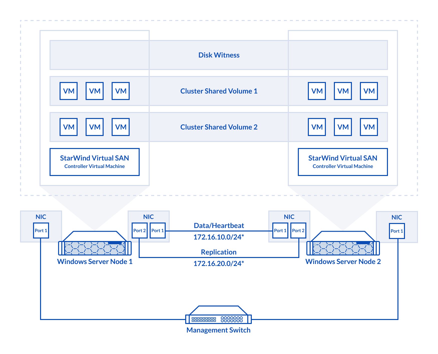
Figure 2. 2-node cluster configuration
In this diagram, the 172.16.10.0/24 subnet is used to discover and connect the iSCSI targets (Data) and for StarWind heartbeat traffic, while the 172.16.20.0/24 subnet is used for the Replication traffic. The Data/Heartbeat and Replication links could be connected either through redundant switches or directly between nodes. The Data/Heartbeat and Replication networks should not share the same physical link to avoid potential performance issues. The management links should also be used for the redundant StarWind heartbeat connections.
Synchronous (active-active) replication ensures real-time synchronization and load balancing between cluster nodes. Each write operation requires confirmation from both storage nodes, guaranteeing reliable data transfers, which demands low-latency, high-bandwidth networks, as mirroring could fail on high-latency connections. In case when the node gets all the replication connections broken to the partner nodes (got isolated) and there is no way to get the partner state, the node may “assume” that the partner nodes are offline and could continue operations on a single-node mode, able to accept write commands from the initiators and use data written to it. A scenario when the data is written independently to each node during the replication connection failure is called a “split-brain,” which can result in data corruption or inconsistency. To minimize or prevent split-brain scenarios, StarWind VSAN provides two failover strategies:
Heartbeat Failover Strategy
This strategy utilizes an alternate network connection, referred to as a heartbeat link, to monitor the availability of partner nodes. If replication networks fail but the heartbeat link remains active, StarWind services communicate through it to determine the partner node’s state or exchange commands. The high-availability (HA) device with the lowest priority is then marked as unsynchronized and blocked from further read/write operations until the replication network is restored. Simultaneously, the partner device on the synchronized node flushes data from its cache to disk, ensuring data integrity in the event of an unexpected node failure.
Given the critical role of heartbeat links in maintaining data consistency, it is strongly recommended to configure multiple independent heartbeat channels during replica creation. This enhances stability and minimizes the risk of a “split-brain” scenario.
With the heartbeat failover strategy, the storage cluster can continue operating with only one StarWind node available.
Node Majority Failover Strategy
This strategy ensures that the system continues operating only when more than half of the nodes are active. Nodes that fall into the minority automatically stop accepting read and write requests, and their HA devices are marked as unsynchronized. Node Majority does not require heartbeat links; instead, it calculates the majority based on “votes.” The failure-handling process occurs when the node has detected the absence of the replication connection with the partner. The main requirement for keeping the node operational is an active connection with more than half of the HA device’s nodes.
In a two-node HA setup (which has only 2 “votes”), all nodes will be disconnected if there is a problem on the node itself, or in communication between them. Therefore, to keep at least one node active, the Node Majority failover strategy requires the addition of the third Witness node or file share (SMB). The witness participates in the nodes count for the majority, but neither contains data on it nor is involved in processing clients’ requests.
With Node Majority failover strategy, the failure of only one node can be tolerated.
The Witness node can be deployed on any Windows server running StarWind VSAN service. The Witness node also can be deployed as StarWind CVM on a supported hypervisor (Hyper-V, ESXi, Proxmox, etc.). More details about the Node Majority failover strategy are available here: https://www.starwindsoftware.com/blog/whats-split-brain-and-how-to-avoid-it/
3-Node Cluster Configuration
StarWind VSAN supports 3-way storage replica, so in case of 3-node Microsoft Failover Cluster the shared storage can be replicated on each of the nodes ensuring extra redundancy at the storage level.
To deploy a 3-node setup, all nodes must have identical hardware and meet the minimum StarWind VSAN system requirements, including supported OS, memory size, dedicated network interfaces, latency specifications, and minimum connection speed.
In a StarWind VSAN-based hyperconverged infrastructure, compute, storage, and networking are combined into a unified solution. Shared storage, managed by StarWind VSAN running as a Controller Virtual Machine (CVM), is replicated between the nodes hosting the StarWind CVM, the cluster, and the clustered VMs. StarWind VSAN CVMs, which can be installed on the local storage where the OS is installed, must be deployed on each Windows Server to configure the cluster. Local storage, such as physical disks, NVMe drives, or RAID arrays used for data, should be assigned to the StarWind Controller Virtual Machine (CVM).The StarWind CVM manages virtual disks that are replicated with CVMs on other nodes, creating a shared storage pool. This highly available (HA) storage is connected to each server and utilized as cluster storage. Data replication in active-active mode is performed at the block level over dedicated links between the servers. Production VMs managed by the cluster should reside on Cluster Shared Volumes based on StarWind HA devices. A 3-node failover cluster inherently achieves quorum without additional witnesses, as the three nodes provide sufficient votes to determine a majority, however, Witness disk can be created if it’s required.
The diagram below illustrates the network and storage configuration of the 3-node hyperconverged setup.
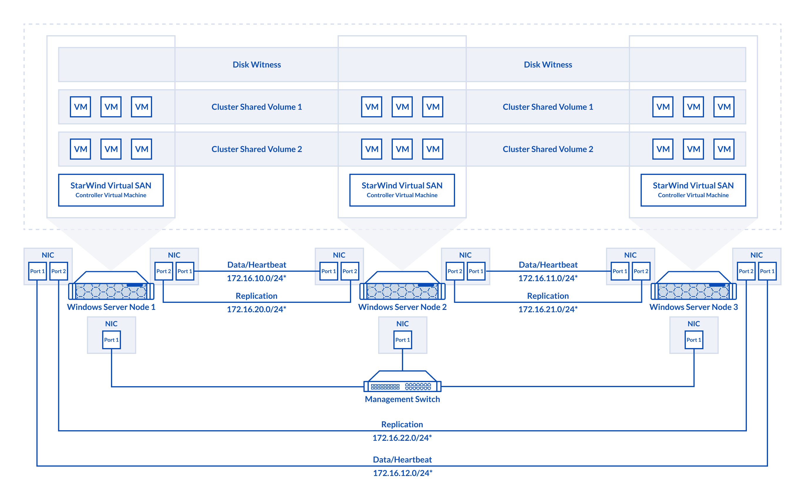
Figure 3. 3-node cluster configuration
In this diagram, 172.16.10.0/24, 172.16.11.0/24,172.16.12.0/24 subnets are used to discover and connect the iSCSI targets (Data) and for StarWind heartbeat traffic, while 172.16.20.0/24,172.16.21.0/24, 172.16.22.0/24 subnets are used for the Replication traffic. The Data/Heartbeat and Replication links could be connected either through redundant switches or directly between nodes. The Data/Heartbeat and Replication networks should not share the same physical link to avoid potential performance issues. The management links should also be used for the redundant StarWind heartbeat connections.
Synchronous (active-active) replication ensures real-time synchronization and load balancing between cluster nodes. Each write operation requires confirmation from both storage nodes, guaranteeing reliable data transfers, which demands low-latency, high-bandwidth networks, as mirroring could fail on high-latency connections. In case when the node gets all the replication connections broken to the partner nodes (got isolated) and there is no way to get the partner state, the node may “assume” that the partner nodes are offline and could continue operations on a single-node mode, able to accept write commands from the initiators and use data written to it. A scenario when the data is written independently to each node during the replication connection failure is called a “split-brain,” which can result in data corruption or inconsistency. To minimize or prevent split-brain scenarios, StarWind VSAN provides two failover strategies:
Heartbeat Failover Strategy
This strategy uses an alternate network connection, known as a heartbeat link, to monitor partner node availability. If replication links fail but the heartbeat remains online, StarWind services communicate via the heartbeat link to identify the partner node state or send the commands to each other. The HA device with the lowest priority is marked as unsynchronized and blocked for further read/write operations until the replication channel resumption. At the same time, the partner device on the synchronized node flushes data from the cache to the disk to preserve data integrity in case the node goes down unexpectedly.
Since heartbeat links are critical for data consistency, it is recommended to assign multiple independent heartbeat channels during replica creation for improved stability and minimize the risk of the “split-brain” issue.
With the heartbeat failover strategy, the storage cluster will continue working with only one StarWind node available.
Node Majority Failover Strategy
This strategy ensures that the system continues operating only when more than half of the nodes are active. Nodes that fall into the minority automatically stop accepting read and write requests, and their HA devices are marked as unsynchronized. Node Majority does not require heartbeat links; instead, it calculates the majority based on “votes.” The failure-handling process occurs when the node has detected the absence of the replication connection with the partner. The main requirement for keeping the node operational is an active connection with more than half of the HA device’s nodes.
In a three-node HA setup (which has 3 “votes”), the system can tolerate the failure of one node while maintaining quorum. However, if two nodes fail, the remaining node will lose the majority and cease operations. Unlike in two-node configurations, a Witness node is not necessary in a three-node setup, as the majority is naturally achieved. More details about the Node Majority failover strategy are available here: https://www.starwindsoftware.com/blog/whats-split-brain-and-how-to-avoid-it/
Prerequisites
StarWind Virtual SAN system requirements
Before installing StarWind Virtual SAN, ensure that the system meets the requirements:
https://www.starwindsoftware.com/system-requirements
Recommended RAID settings for HDD and SSD disks:
https://knowledgebase.starwindsoftware.com/guidance/recommended-raid-settings-for-hdd-and-ssd-disks/
Read StarWind Virtual SAN Best Practices for additional information:
https://www.starwindsoftware.com/resource-library/starwind-virtual-san-best-practices
Preconfiguring cluster nodes
1. Make sure that a domain controller (DC) is configured, and all Windows Server hosts are added to the domain.
NOTE: Follow the recommendations in this KB article regarding the placement of a DC when using StarWind Virtual SAN: https://knowledgebase.starwindsoftware.com/explanation/advice-on-how-to-place-a-domain-controller-in-case-of-starwind-virtual-san-usage/
2. Deploy the Windows Server OS , install the Hyper-V role, Failover Clustering, and Multipath I/O features,on all hosts. This can be done through the Server Manager’s “Add Roles and Features” menu item.
3. Allocate a minimum of 2 network interfaces on each host for a 2-node cluster configuration, and a minimum of four network interfaces on each host for a three-node cluster configuration. These interfaces will be utilized for Data/Heartbeat and Replication traffic.
IMPORTANT:
• Ensure the Data/Heartbeat and Replication networks do not share the same physical link.
• Connect Data/Heartbeat and Replication links either through redundant switches or directly between nodes, as illustrated in Prerequisites: Solution diagram
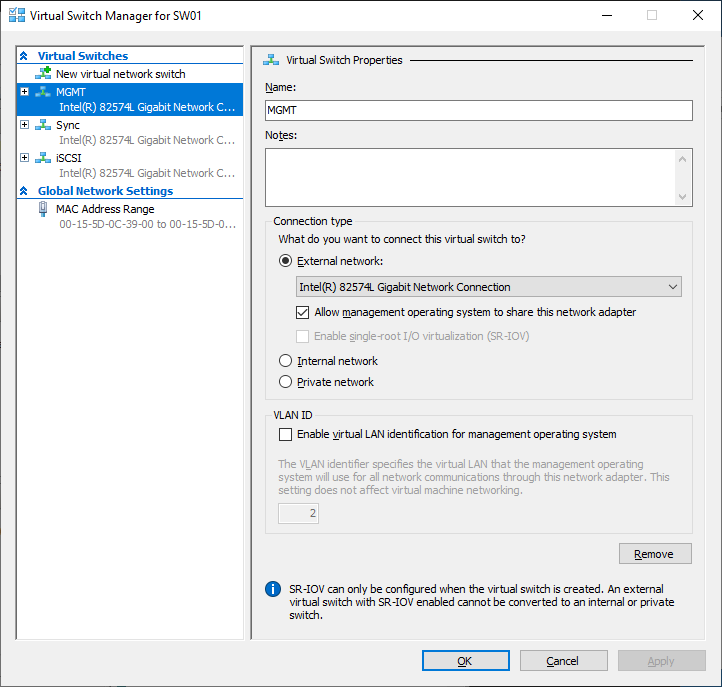
4. Create separate External Virtual Switches for Data/Heartbeat and Replication networks based on the interfaces allocated in the previous step.
In Hyper-V Manager, open Virtual Switch Manager and create two External Virtual Switches: one for the Data/Heartbeat network and another for the Replication network.
5. Configure the IP address on each virtual switch network interface.
In this document, in a 2-node setup, the 172.16.10.0/24 subnet is used to discover and connect the iSCSI targets (Data) and for StarWind heartbeat traffic, while the 172.16.20.0/24 subnet is used for the Replication traffic.
In 3-node setup, 172.16.10.x, 172.16.11.x,172.16.12.x subnets are used to discover and connect the iSCSI targets (Data) and for StarWind heartbeat traffic, while 172.16.20.x,172.16.21.x, 172.16.22.x subnets are used for the Replication traffic.
NOTE: If the NIC supports SR-IOV, enable it to optimize performance. An additional internal virtual switch is required for the Data/Heartbeat Connection. For further details, contact StarWind Support.
6. Set the Jumbo Frames to 9014 bytes on the Data/Heartbeat and Replication network interfaces either manually or by using the following PowerShell script:
$Datas = (Get-NetAdapter -Name "*Data*").Name
$Replications = (Get-NetAdapter -Name "*Replication*").Name
foreach ($Data in $Datas) {
Set-NetAdapterAdvancedProperty -Name “$Data” -RegistryKeyword “*JumboPacket” -Registryvalue 9014
Get-NetAdapterAdvancedProperty -Name "$Data" -RegistryKeyword “*JumboPacket”
}
foreach ($Replication in $Replications) {
Set-NetAdapterAdvancedProperty -Name “$Replication” -RegistryKeyword “*JumboPacket” -Registryvalue 9014
Get-NetAdapterAdvancedProperty -Name "$Replication" -RegistryKeyword “*JumboPacket”
}
This script sets Jumbo Frames size to 9014 bytes on all network interfaces of the current host that include ‘Data’ or ‘Replication’ in their names.
NOTE: The Jumbo Frames/MTU size should be changed only on the paused node in the cluster and with stopped StarWind VSAN service on the node in question. Additionally, if the Data/Heartbeat or Replication networks are connected through switches, enable Jumbo Frames on all involved switches as well with paused node and stopped StarWind VSAN service. This requirement is needed to avoid split-brain during the change when network connection could be interrupted almost simultaneously on different links.
IMPORTANT: Enabling jumbo frames/MTU could bring stability and performance issues on some network adapters depending on the drivers and firmware used. In such cases please update the driver/firmware or do not change Jumbo Frames/MTU size.
7. Open the MPIO Properties: Start -> Windows Administrative Tools -> MPIO, or run the following PowerShell command:
mpiocpl
8. In the Discover Multi-Paths tab, select the Add support for iSCSI devices checkbox and click Add.
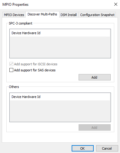
9. When prompted to restart the server, click Yes to proceed.
10. Repeat the steps above on each host.
Deploying StarWind Virtual SAN CVM
1. Download the zip archive containing StarWind Virtual SAN CVM from
https://www.starwindsoftware.com/vsan#download
2. Extract the virtual machine files on the server where StarWind Virtual SAN CVM will be deployed.
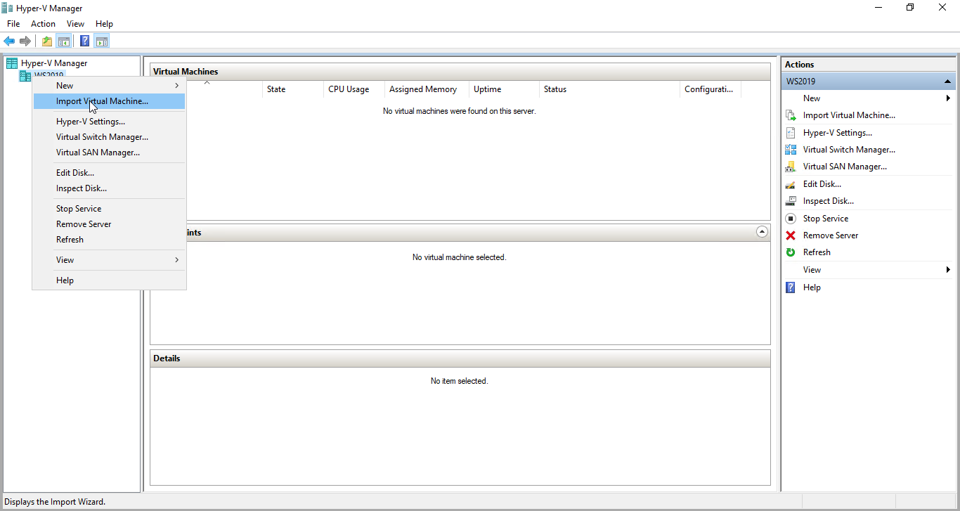
3. Open Hyper-V Manager and launch the Import Virtual Machine wizard.
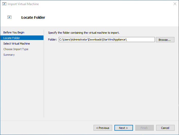
4. On the Locate Folder step of the wizard, navigate to the location of the StarWind Virtual SAN CVM template folder, select the folder, and then click Next.
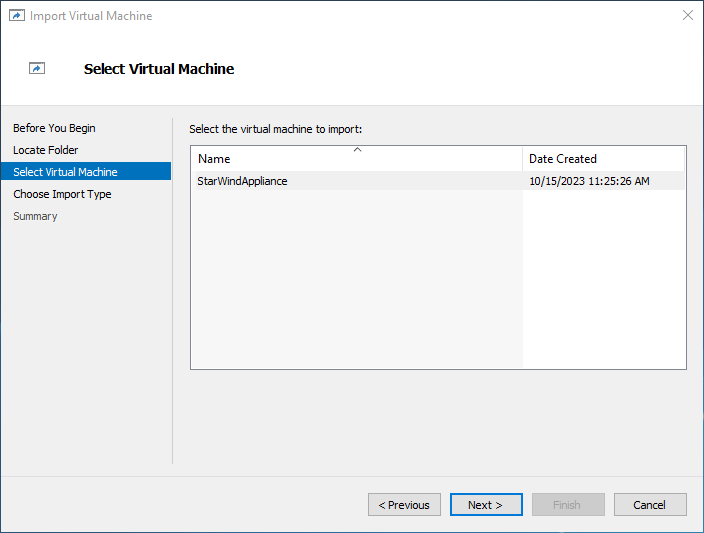
5. On the Select Virtual Machine step, click Next.
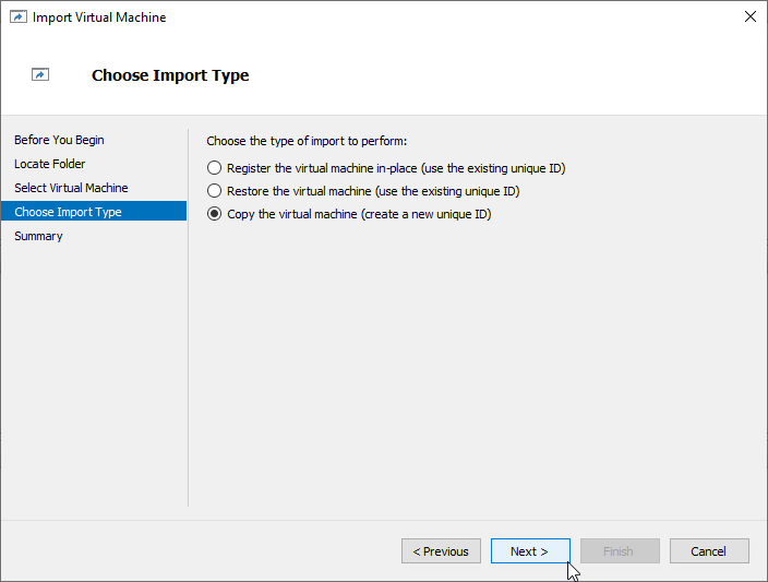
6. On the Choose Import Type step, select the Copy the virtual machine import type and click Next.
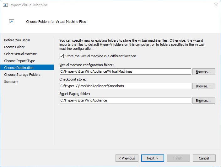
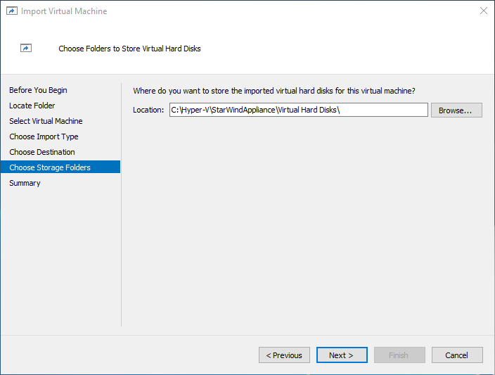
7. On the Choose Destination and Choose Storage Folders steps, specify folders to store virtual machine files, such as configuration, snapshots, smart paging, and virtual disks. Then, click Next.
NOTE: It’s recommended to deploy StarWind Virtual SAN CVM on a separate storage device accessible to the hypervisor host, e.g., a BOSS card, etc.
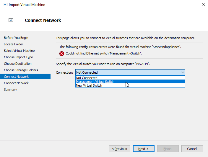
8. On the Connect Network step, the wizard will validate the network settings.
Below are the default names for virtual switches:
- The Management network virtual switch is named “Management vSwitch”
- The Data/Heartbeat network virtual switch is named “Data/iSCSI vSwitch”
- The Replication network virtual switch is named “Replication/Sync vSwitch”
If the existing virtual switches have different names, manually select the appropriate ones from the drop-down list. Then, click Next.

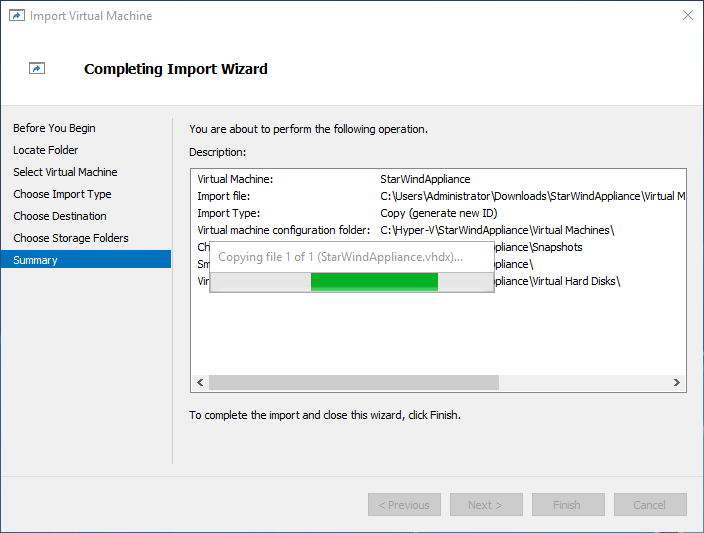
9. On the Summary step, review the configuration settings and click Finish to begin the import process.

10. Repeat steps 1 through 9 on each host where StarWind CVM should be deployed.
Add physical disks
Attach physical storage to StarWind Virtual SAN Controller VM:
- Ensure that all physical drives are connected through an HBA or RAID controller.
- To get the optimal storage performance, add HBA, RAID controllers, or NVMe SSD drives to StarWind CVM via a passthrough device.
For detailed instructions, refer to Microsoft’s documentation on DDA. Also, find the storage provisioning guidelines in the KB article.
Initial Configuration Wizard
1. Start the StarWind Virtual SAN Controller Virtual Machine.
2. Launch the VM console to view the VM boot process and obtain the IPv4 address of the Management network interface.
NOTE: If the VM does not acquire an IPv4 address from a DHCP server, use the Text-based User Interface (TUI) to set up the Management network manually.
Default credentials for TUI: user/rds123RDS
3. Using a web browser, open a new tab and enter the VM’s IPv4 address to access the StarWind VSAN Web Interface. On the Your connection is not private screen, click Advanced and then select Continue to…

4. On the Welcome to StarWind Appliance screen, click Start to launch the Initial Configuration Wizard.
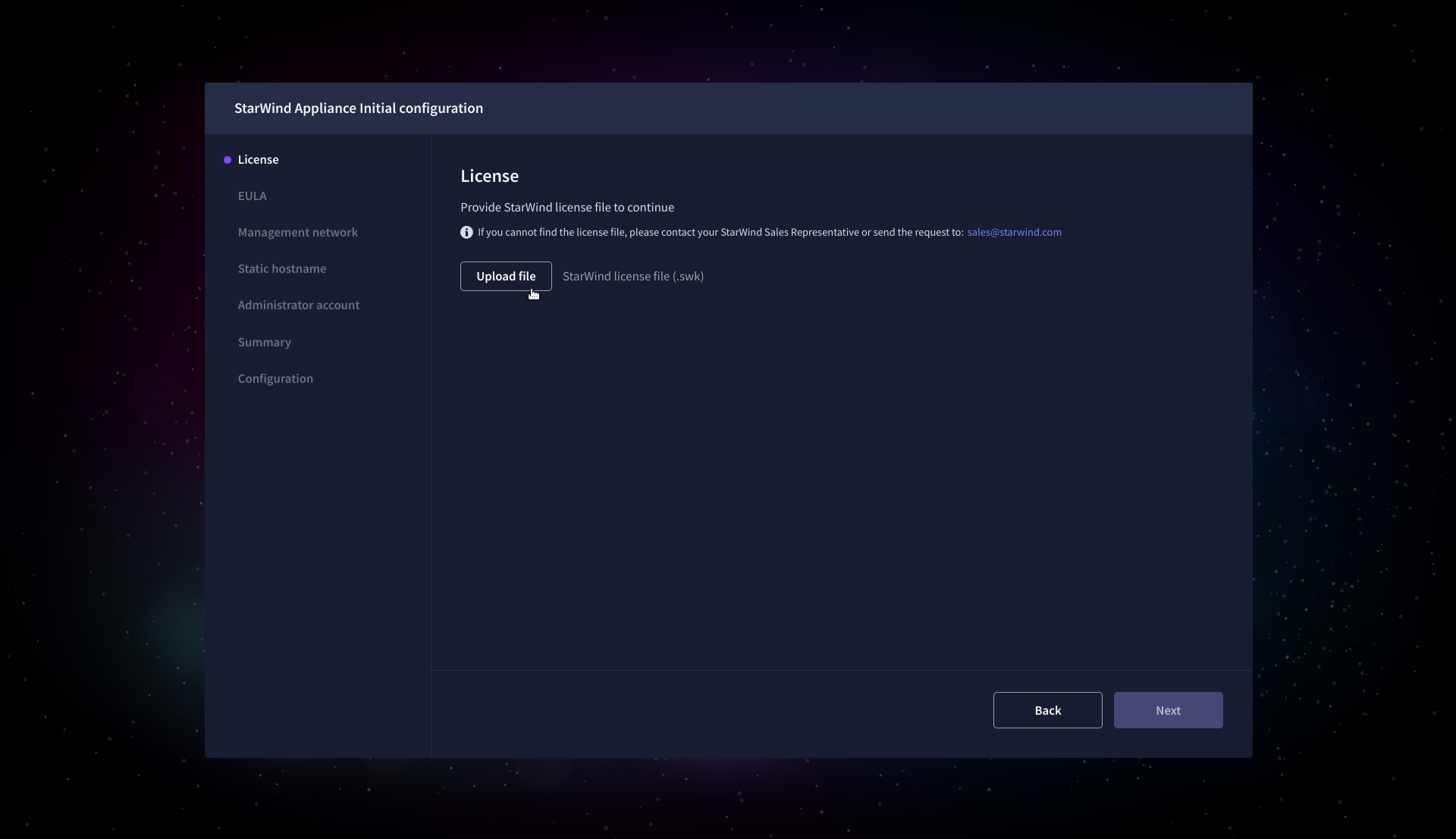
5. On the License step, upload the StarWind Virtual SAN license file.
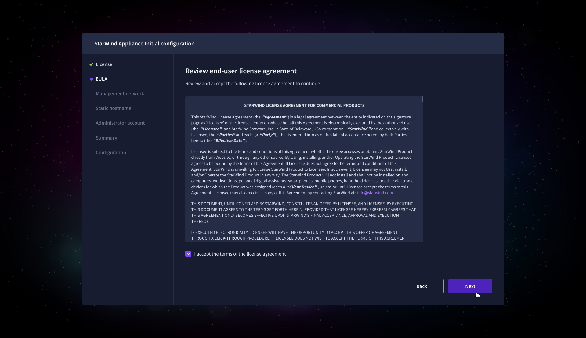
6. On the EULA step, read and accept the End User License Agreement to continue.
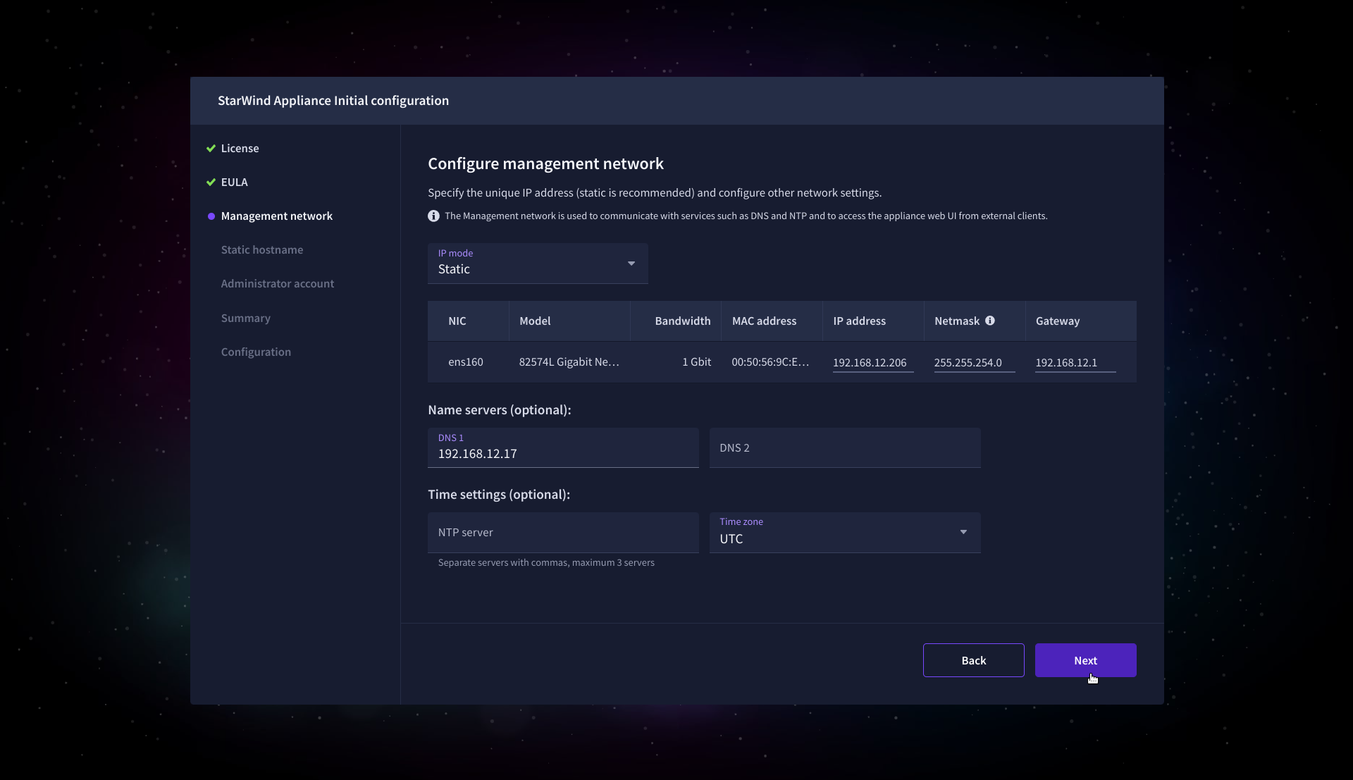
7. On the Management network step, review or edit the network settings and click Next.
IMPORTANT: The use of Static IP mode is highly recommended.
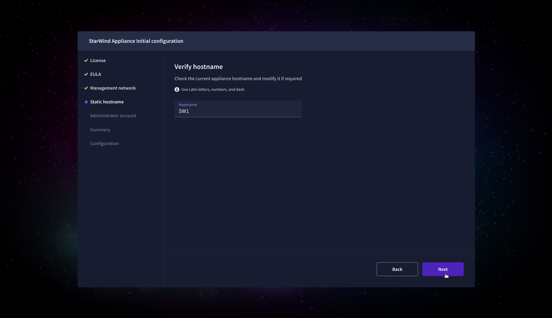
8. On the Static hostname, specify the hostname for the virtual machine and click Next.
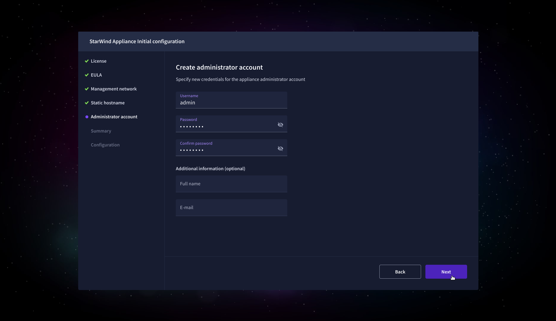
9. On the Administrator account step, specify the credentials for the new StarWind Virtual SAN administrator account and click Next.
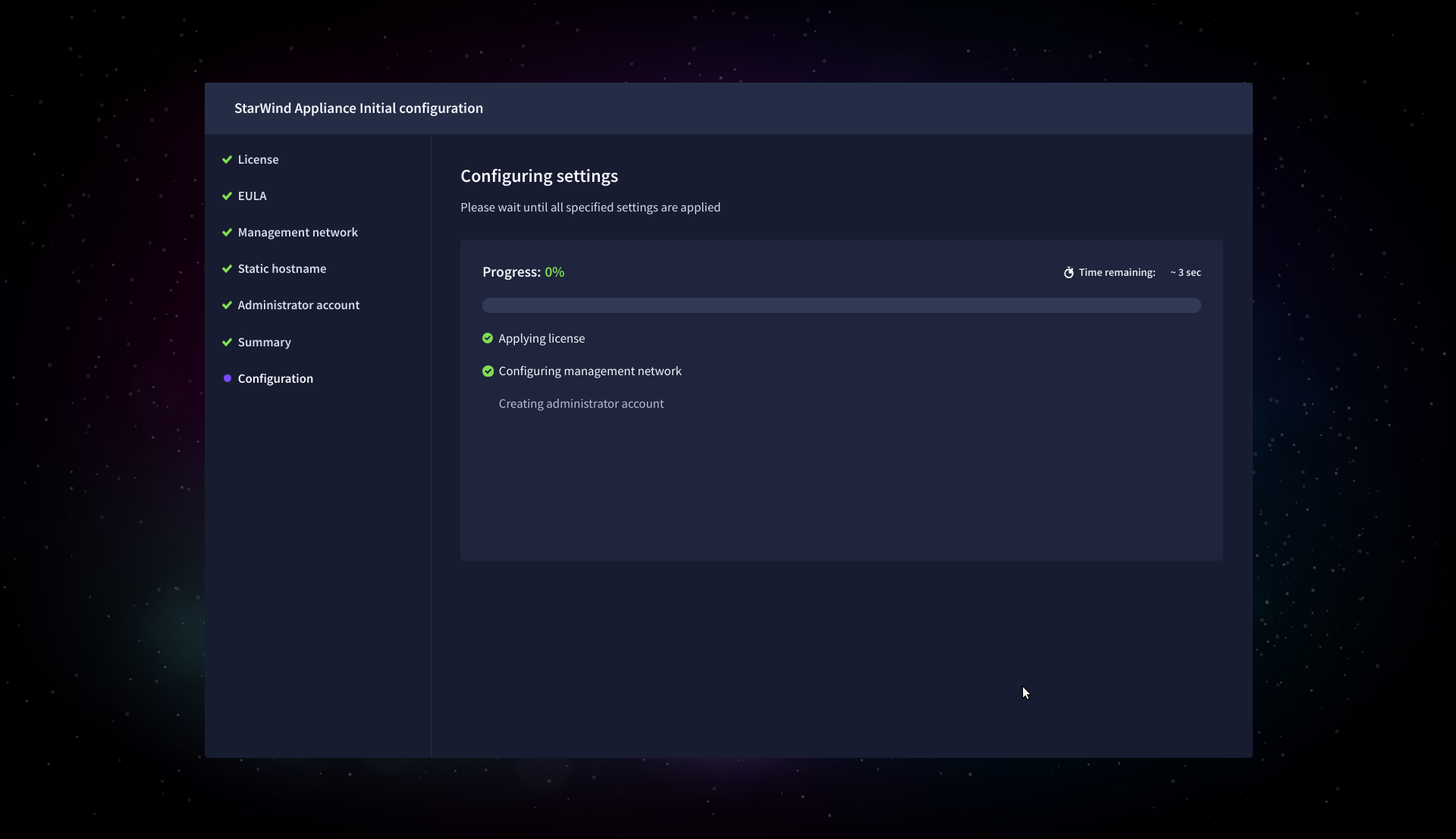
10. Wait until the Initial Configuration Wizard configures StarWind Virtual SAN for you.
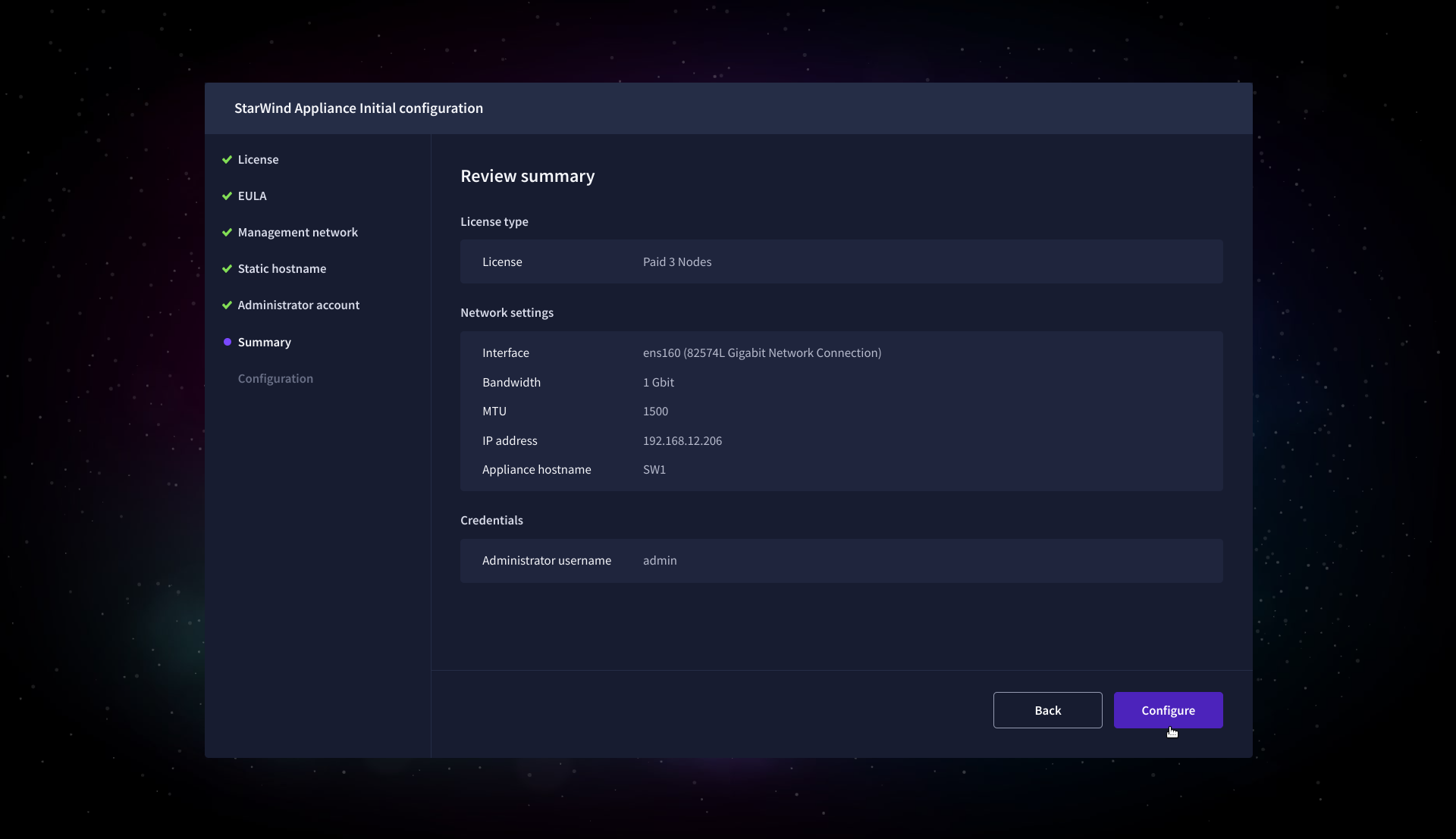
11. Please standby until the Initial Configuration Wizard configures StarWind VSAN for you.
12. After the configuration process is completed, click Finish to install the StarWind vCenter Plugin immediately, or uncheck the checkbox to skip this step and proceed to the Login page.
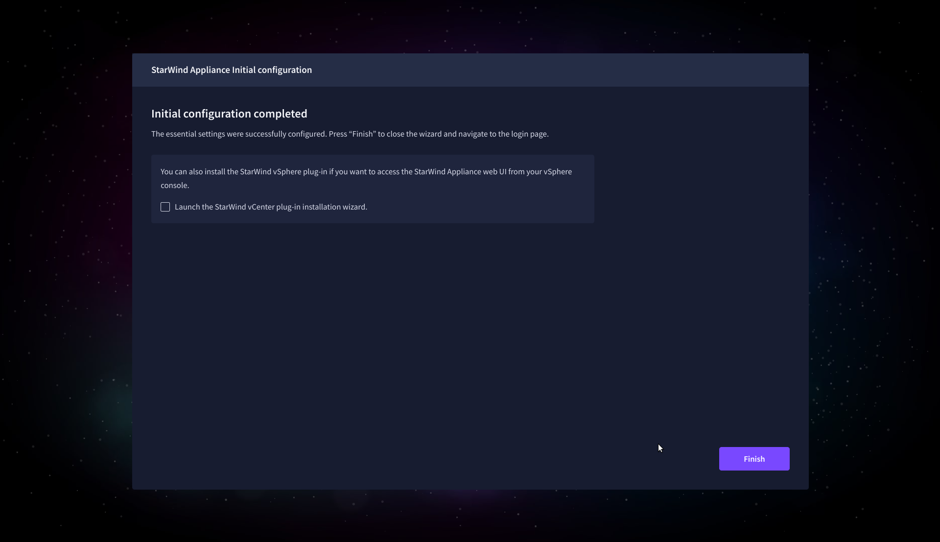
13. Repeat steps 1 through 12 on each Windows Server host.
Add Appliance
To create replicated, highly available storage, add partner appliances that use the same StarWind Virtual SAN license key.
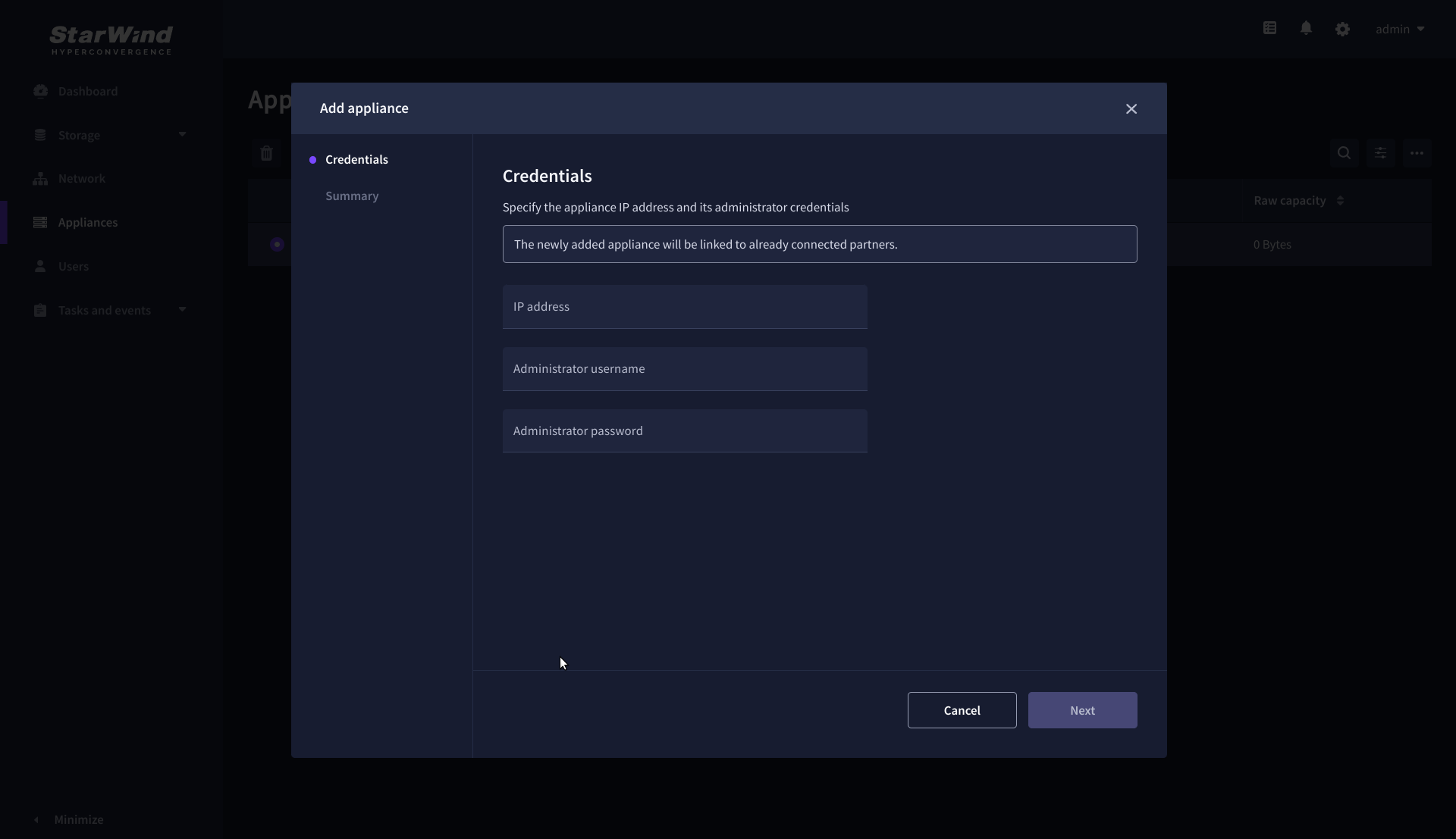
1. Navigate to the Appliances page and click Add to open the Add appliance wizard.
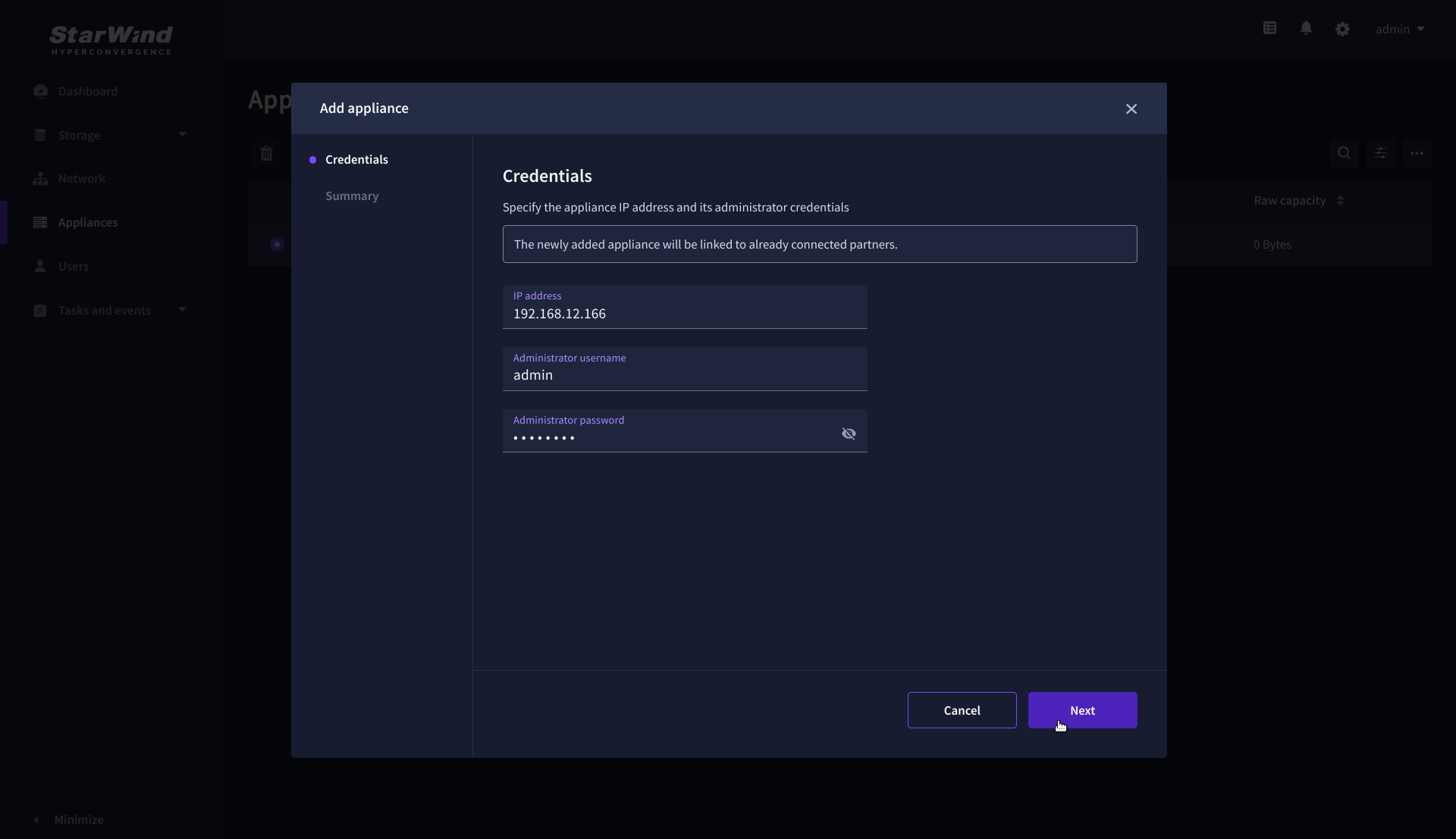
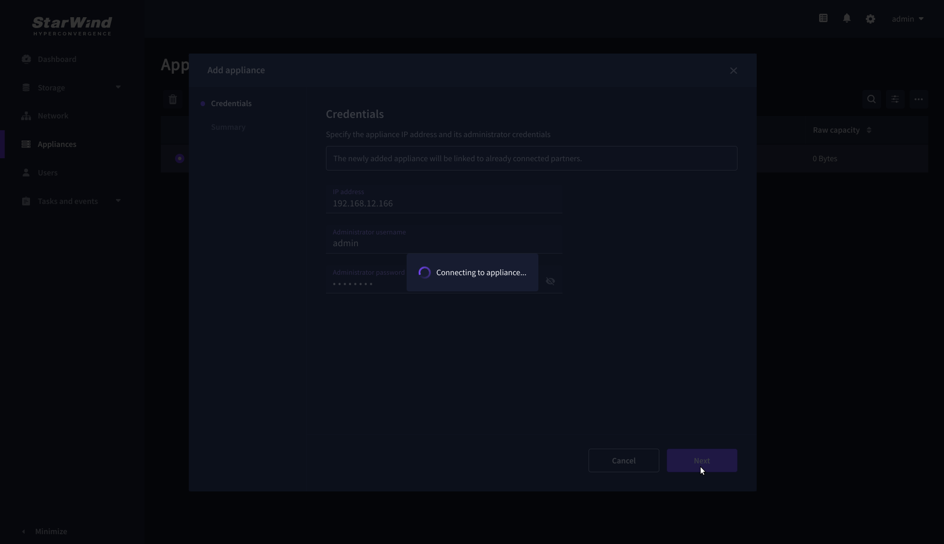
2. On the Credentials step, enter the IP address and credentials for the partner StarWind Virtual SAN appliance, then click Next.
3. Provide credentials of partner appliance.
4. Wait for the connection to be established and the settings to be validated
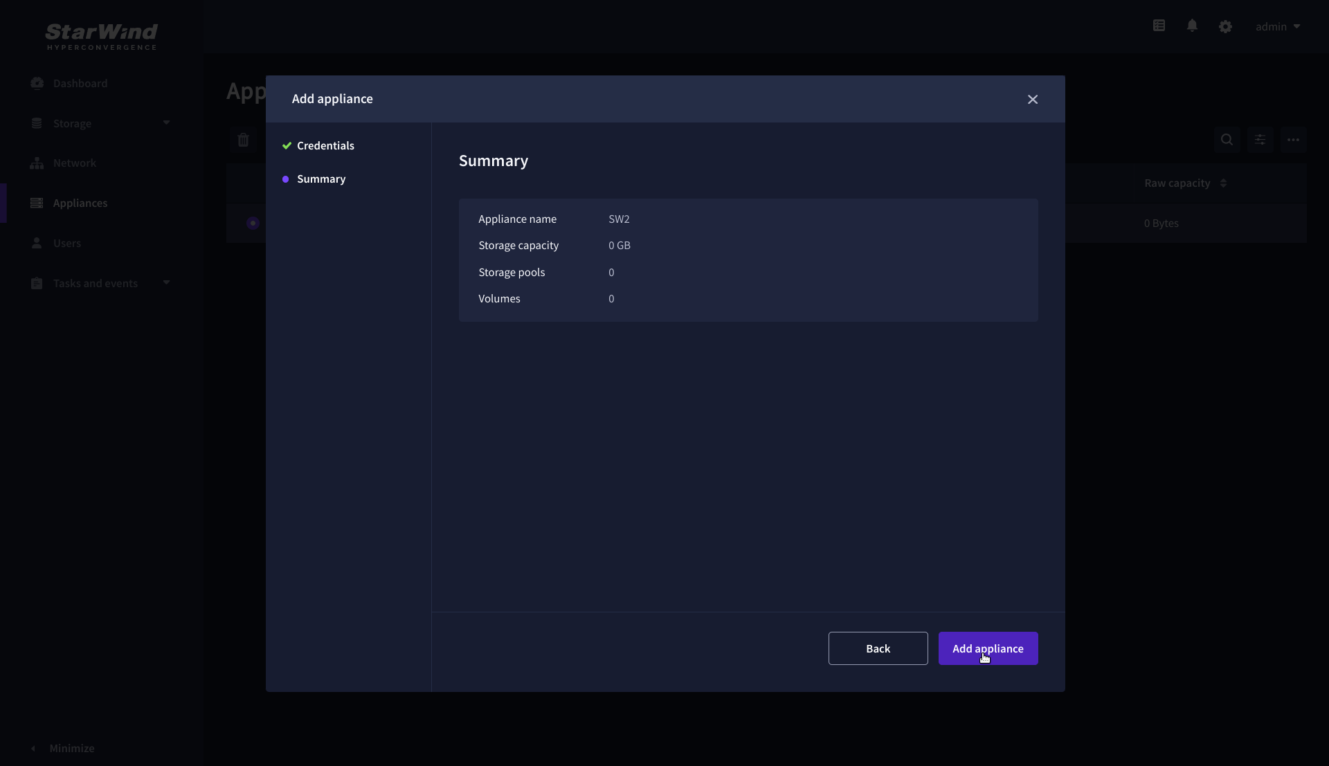
5. On the Summary step, review the properties of the partner appliance, then click Add Appliance.
Configure HA networking
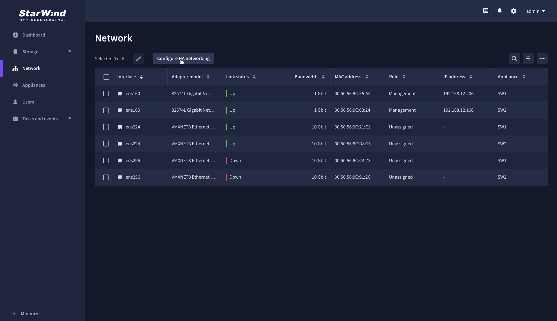
1. Navigate to the Network page and open Configure HA networking wizard.
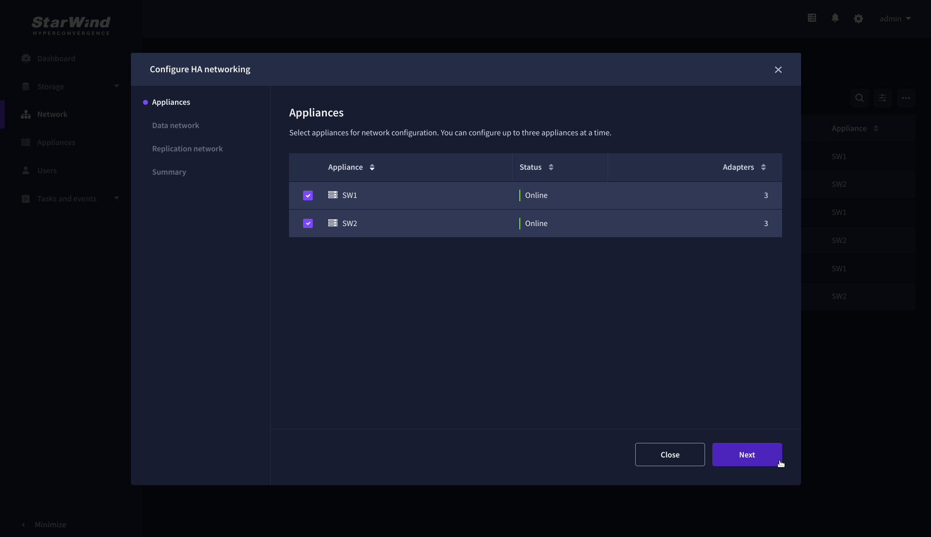
2. On the Appliances step, select either 2 partner appliances to configure two-way replication, or 3 appliances for three-way replication, then click Next.
NOTE: The number of appliances in the cluster is limited by your StarWind Virtual SAN license.
3. On the Data Network step, select the network interfaces designated to carry iSCSI or NVMe-oF storage traffic. Assign and configure at least one interface on each appliance (in our example: 172.16.10.10 and 172.16.10.20) with a static IP address in a unique network (subnet), specify the subnet mask and Cluster MTU size.
IMPORTANT: For a redundant, high-availability configuration, configure at least 2 network interfaces on each appliance. Ensure that the Data Network interfaces are interconnected between appliances through multiple direct links or via redundant switches.
4. Assign MTU value on all selected network adapters, e.g. 1500 or 9000 bytes. If you are using network switches with the selected Data Network adapters, ensure that they are configured with the same MTU size value. In case of MTU settings mismatch, stability and performance issues might occur on the whole setup.
NOTE: Setting MTU to 9000 bytes on some physical adapters (like Intel Ethernet Network Adapter X710, Broadcom network adapters, etc.) might cause stability and performance issues depending on the installed network driver. To avoid them, use 1500 bytes MTU size or install the stable version of the driver.
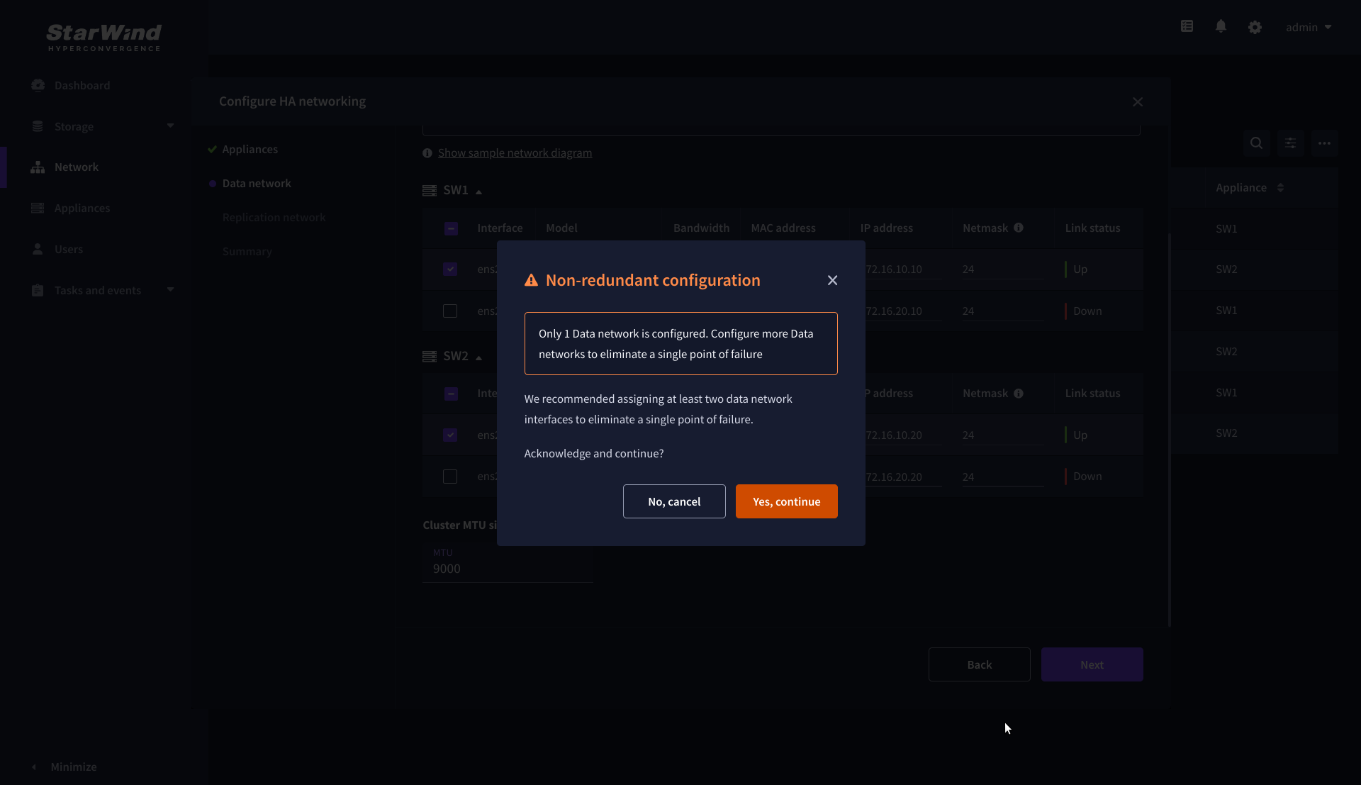
5. Once configured, click Next to validate network settings.

6. The warning might appear if a single data interface is configured. Click Yes, continue to proceed with the configuration.
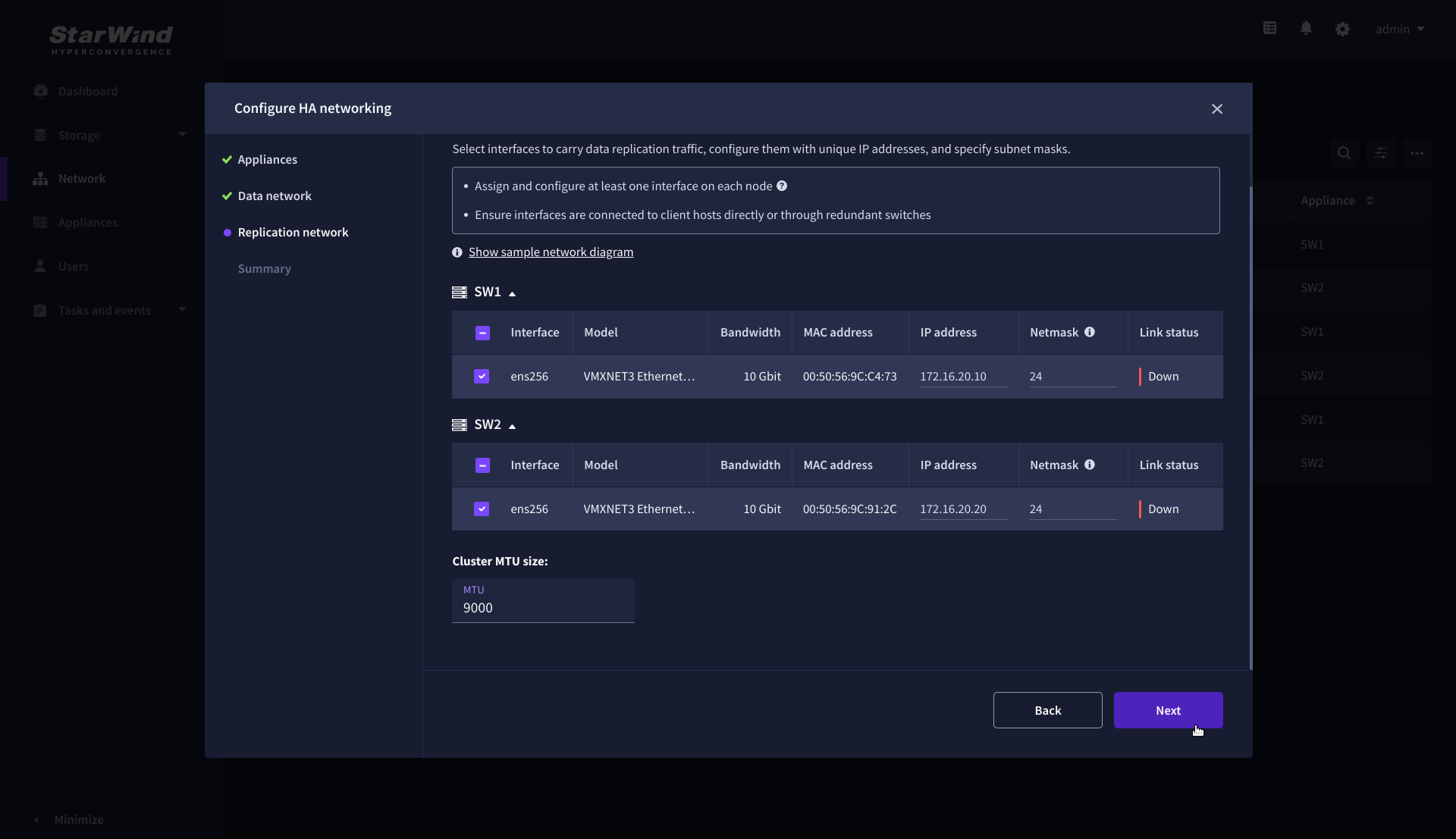
7. On the Replication Network step, select the network interfaces designated to carry the traffic for synchronous replication. Assign and configure at least one interface on each appliance with a static IP address in a unique network (subnet), specify the subnet mask and Cluster MTU size.
IMPORTANT: For a redundant, high-availability configuration, configure at least 2 network interfaces on each appliance. Ensure that the Replication Network interfaces are interconnected between appliances through multiple direct links or via redundant switches.
8. Assign MTU value on all selected network adapters, e.g. 1500 or 9000 bytes. If you are using network switches with the selected Replication Network adapters, ensure that they are configured with the same MTU size value. In case of MTU settings mismatch, stability and performance issues might occur on the whole setup.
NOTE: Setting MTU to 9000 bytes on some physical adapters (like Intel Ethernet Network Adapter X710, Broadcom network adapters, etc.) might cause stability and performance issues depending on the installed network driver. To avoid them, use 1500 bytes MTU size or install the stable version of the driver.
9. Once configured, click Next to validate network settings.
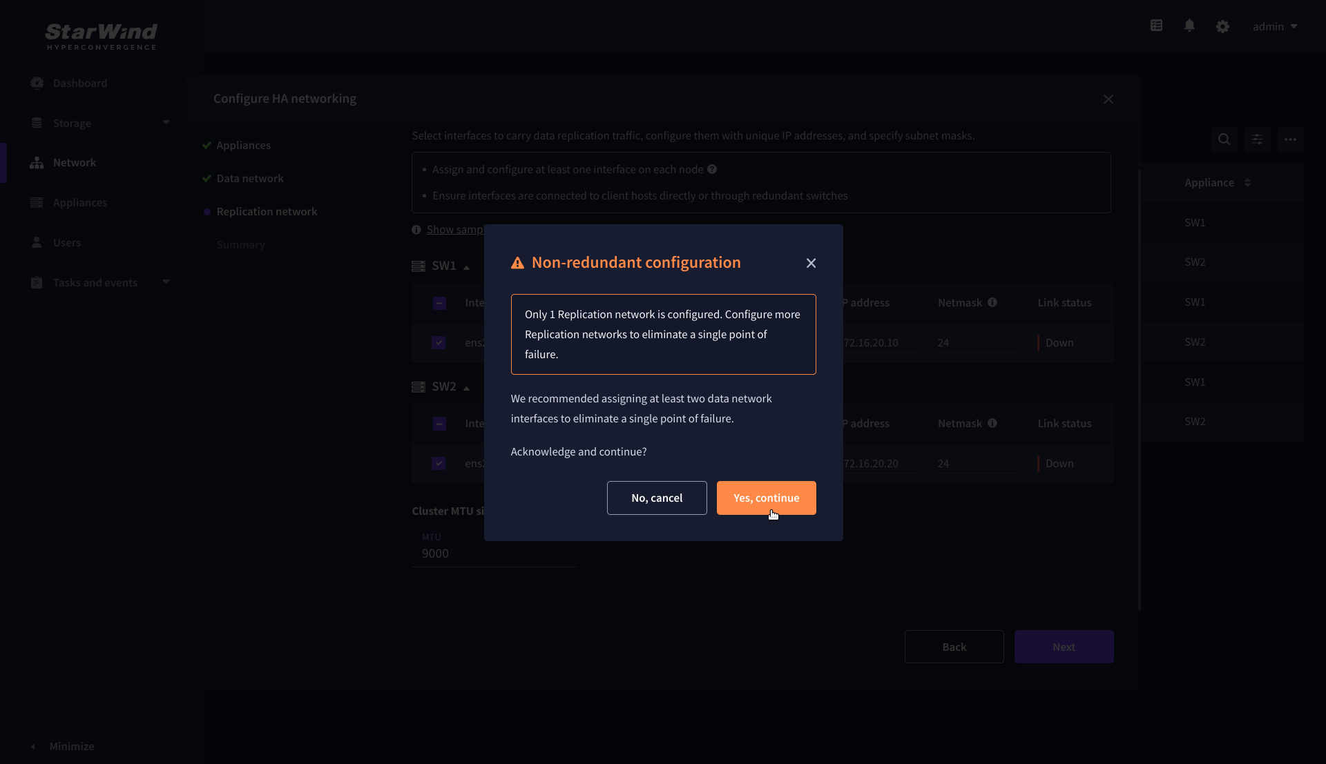
10. If only one Replication Network interface is configured on each partner appliance, a warning message will pop up. Click Yes, continue to acknowledge the warning and proceed.
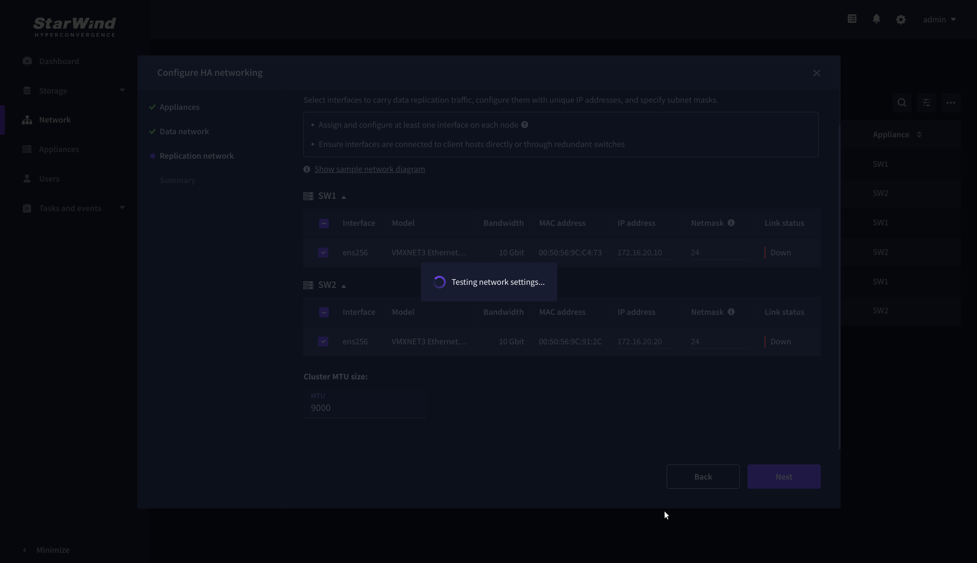
11. Wait for the configuration completion.
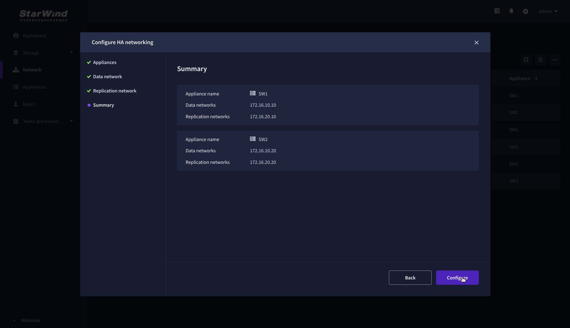
12. On the Summary step, review the specified network settings and click Configure to apply the changes.
Create Storage Pool
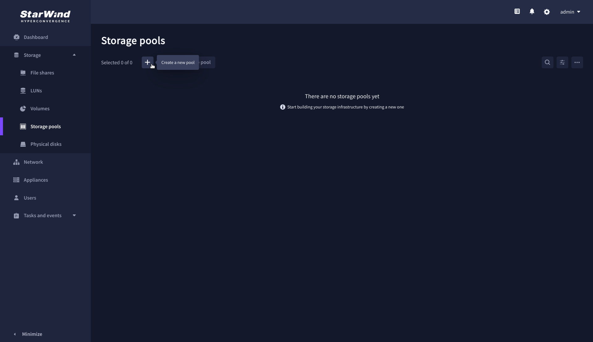
1. Navigate to the Storage pools page and click the + button to open the Create storage pool wizard .
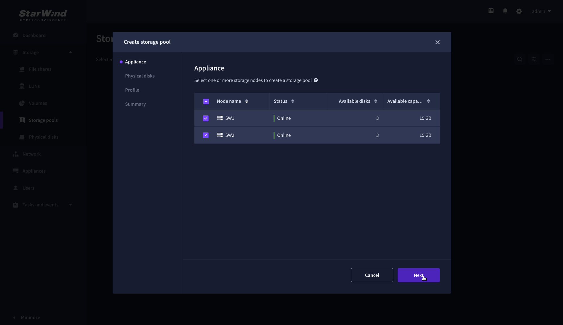
2. On the Appliance step, select partner appliances on which to create new storage pools, then click Next.
NOTE: Select 2 appliances for configuring storage pools if you are deploying a two-node cluster with two-way replication, or select 3 appliances for configuring a three-node cluster with a three-way mirror.
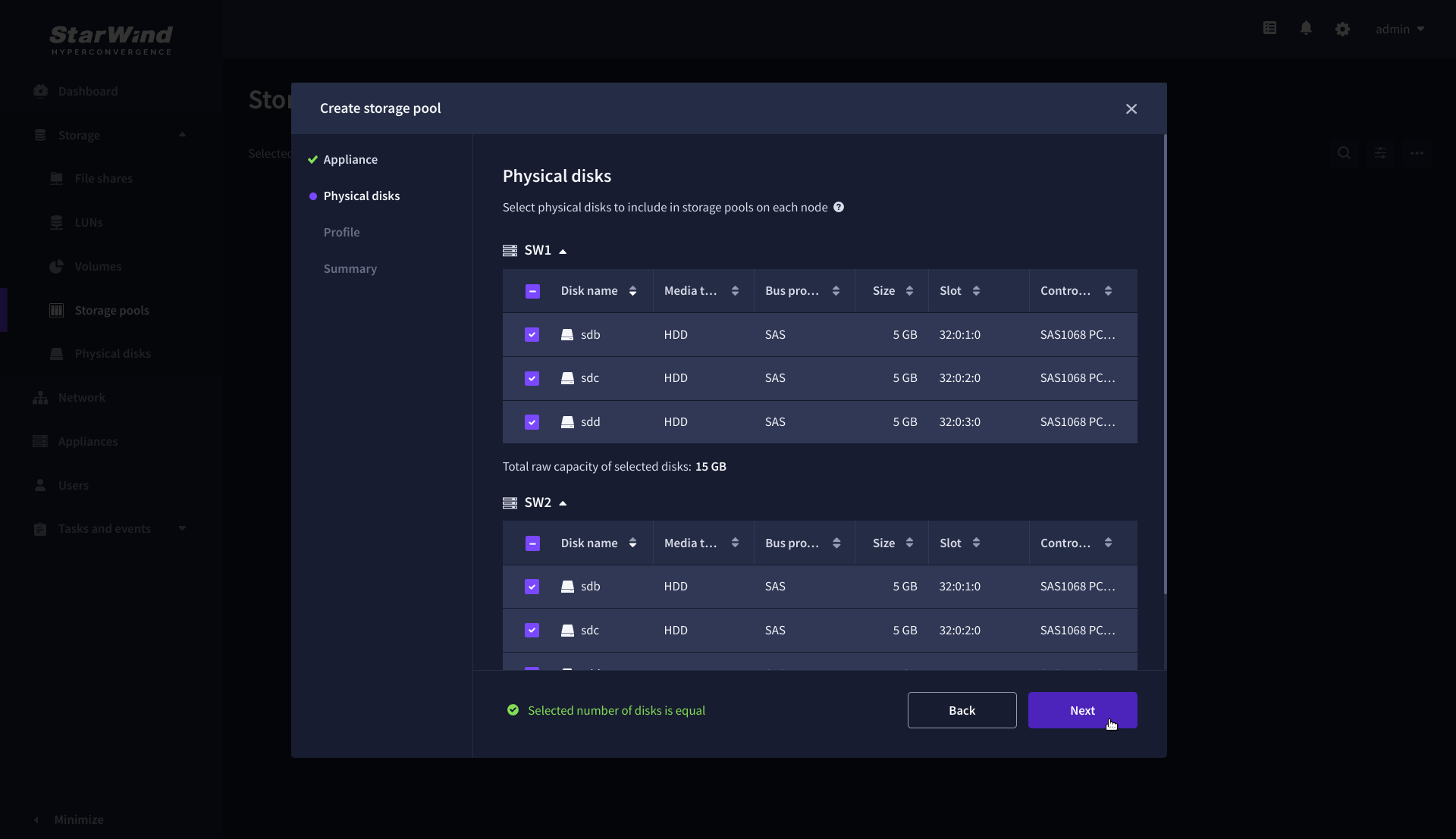
3. On the Physical disks step, select physical disks to be pooled on each node, then click Next.
IMPORTANT: Select an identical type and number of disks on each appliance to create storage pools with a uniform configuration.
4. On the Profile step, select one of the preconfigured storage profiles, or choose Manual to configure the storage pool manually based on your redundancy, capacity, and performance requirements, then click Next.
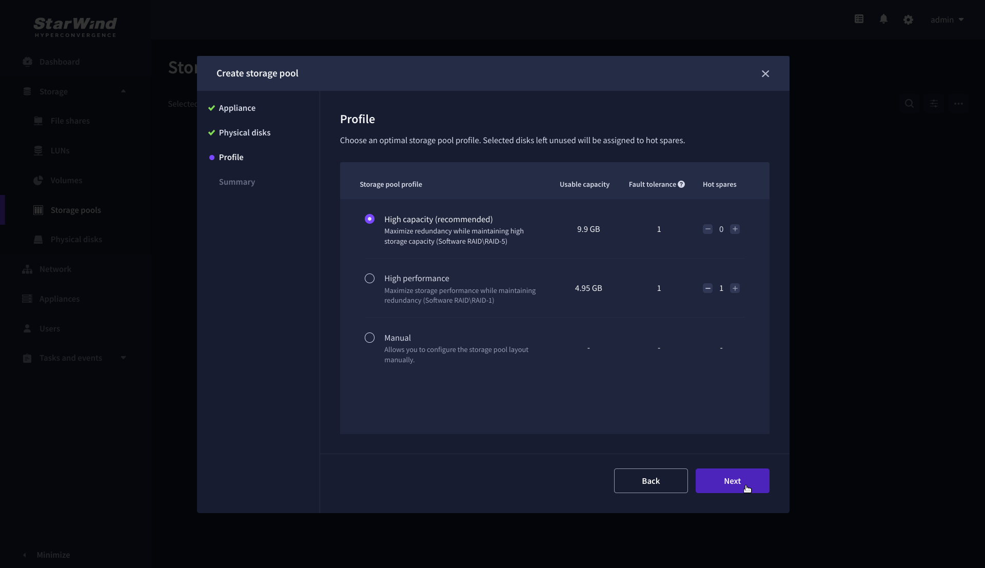
NOTE: Hardware RAID, Linux Software RAID, and ZFS storage pools are supported. To simplify the configuration of storage pools, preconfigured storage profiles are provided. These profiles recommend a pool type and layout based on the attached storage:
- High capacity – creates Linux Software RAID-5 to maximize storage capacity while maintaining redundancy.
- High performance – creates Linux Software RAID-10 to maximize storage performance while maintaining redundancy.
- Hardware RAID – configures a hardware RAID virtual disk as a storage pool. This option is available only if a hardware RAID controller is passed through to the StarWind Virtual SAN.
- Better redundancy – creates ZFS Striped RAID-Z2 (RAID 60) to maximize redundancy while maintaining high storage capacity.
- Manual – allows users to configure any storage pool type and layout with the attached storage.
5. On the Summary step, review the storage pool settings and click Create to configure new storage pools on the selected appliances.
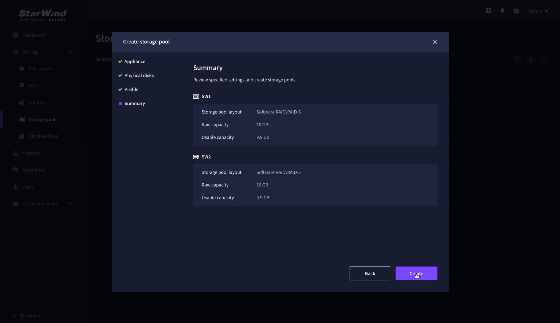
NOTE: The storage pool configuration may take some time, depending on the type of pooled storage and the total storage capacity. Once the pools are created, a notification will appear in the upper right corner of the Web UI.
IMPORTANT: In some cases, additional tweaks are required to optimize the storage performance of the disks added to the Controller Virtual Machine. Please follow the steps in this KB to change the scheduler type depending on the disks type: https://knowledgebase.starwindsoftware.com/guidance/starwind-vsan-for-vsphere-changing-linux-i-o-scheduler-to-optimize-storage-performance/
Create Volume
1. Navigate to the Volumes page and click the + button to open the Create volume wizard.

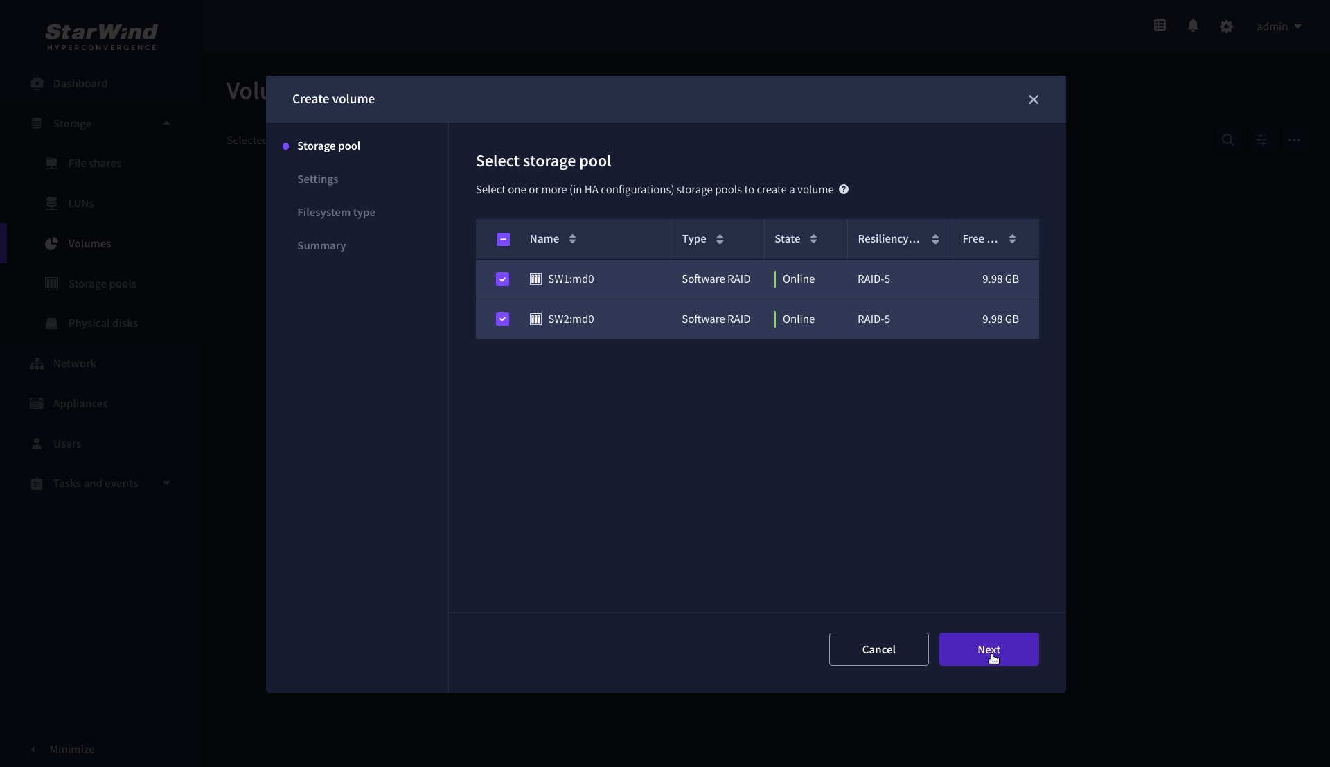
2. On the Storage pool step, select partner appliances on which to create new volumes, then click Next.
NOTE: Select 2 appliances for configuring volumes if you are deploying a two-node cluster with two-way replication, or select 3 appliances for configuring a three-node cluster with a three-way mirror.
3. On the Settings step, specify the volume name and size, then click Next.

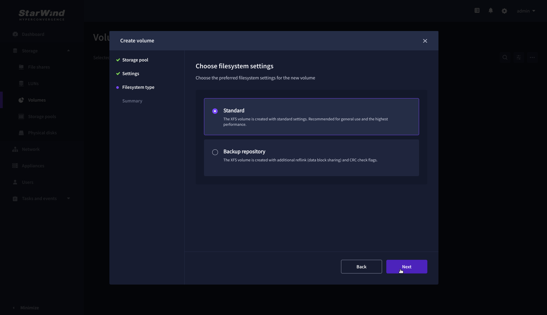
4. On the Filesystem type step, select Standard, then click Next.
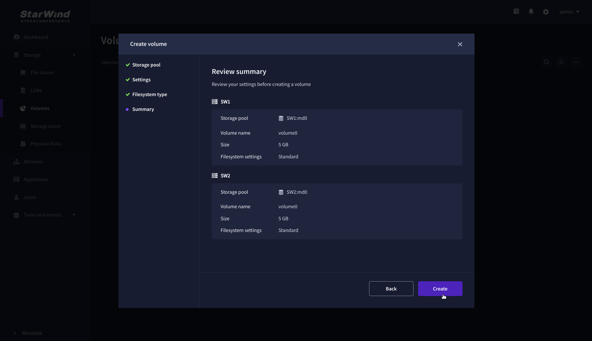
5. Review Summary and click the Create button to create the pool.
Create HA LUN using WebUI
This section describes how to create LUN in Web UI. This option is available for the setups with Commercial, Trial, and NFR licenses applied.
For setups with a Free license applied, the PowerShell script should be used to create the LUN – please follow the steps described in the section: Create StarWind HA LUNs using PowerShell
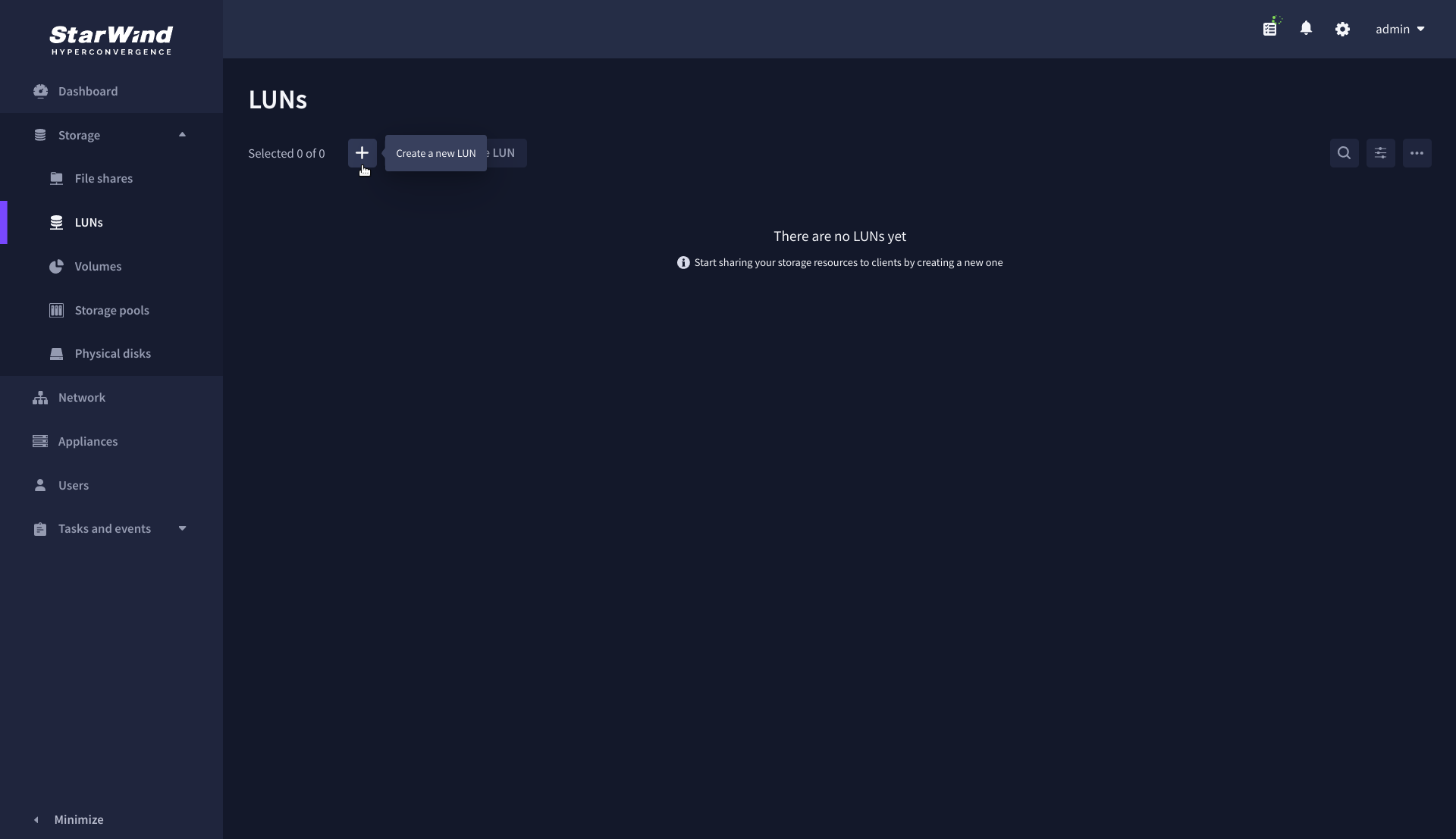
1. Navigate to the LUNs page and click the + button to open the Create LUN wizard.
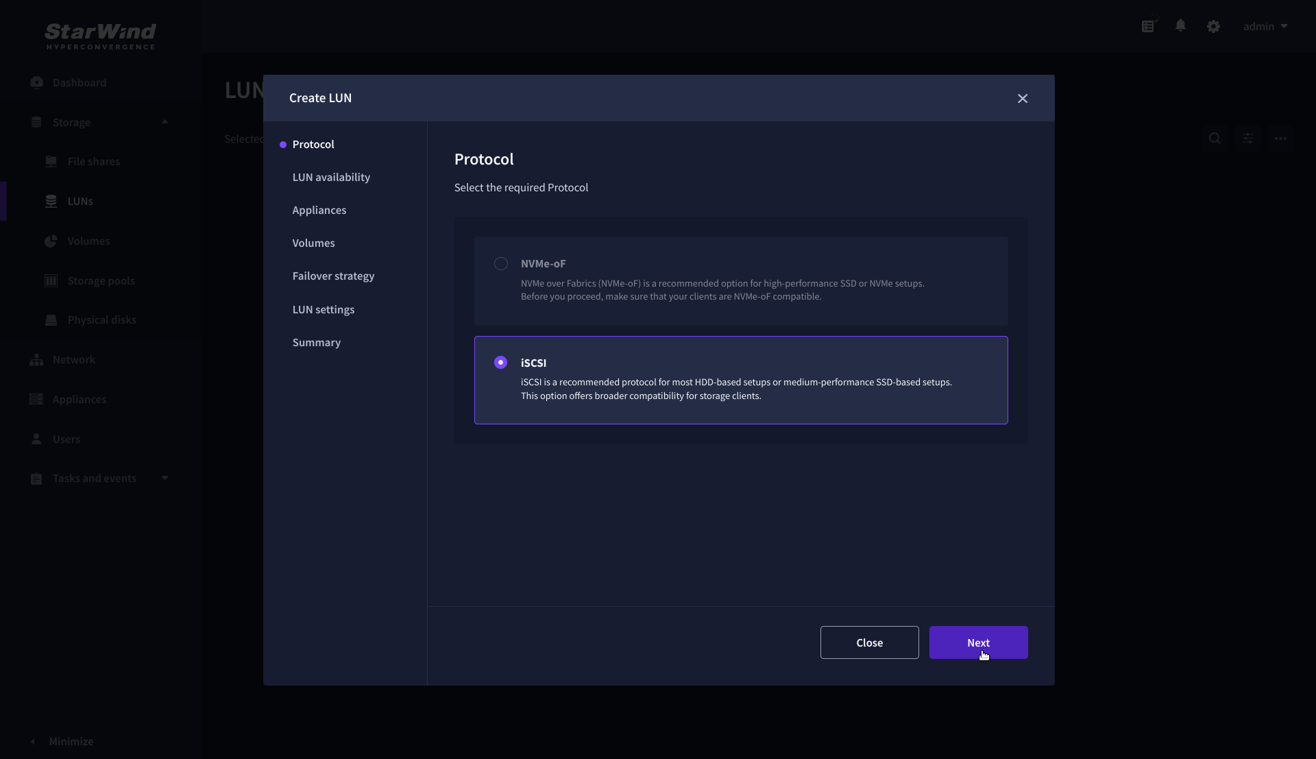
2. On the Protocols step, select the preferred storage protocol and click Next.
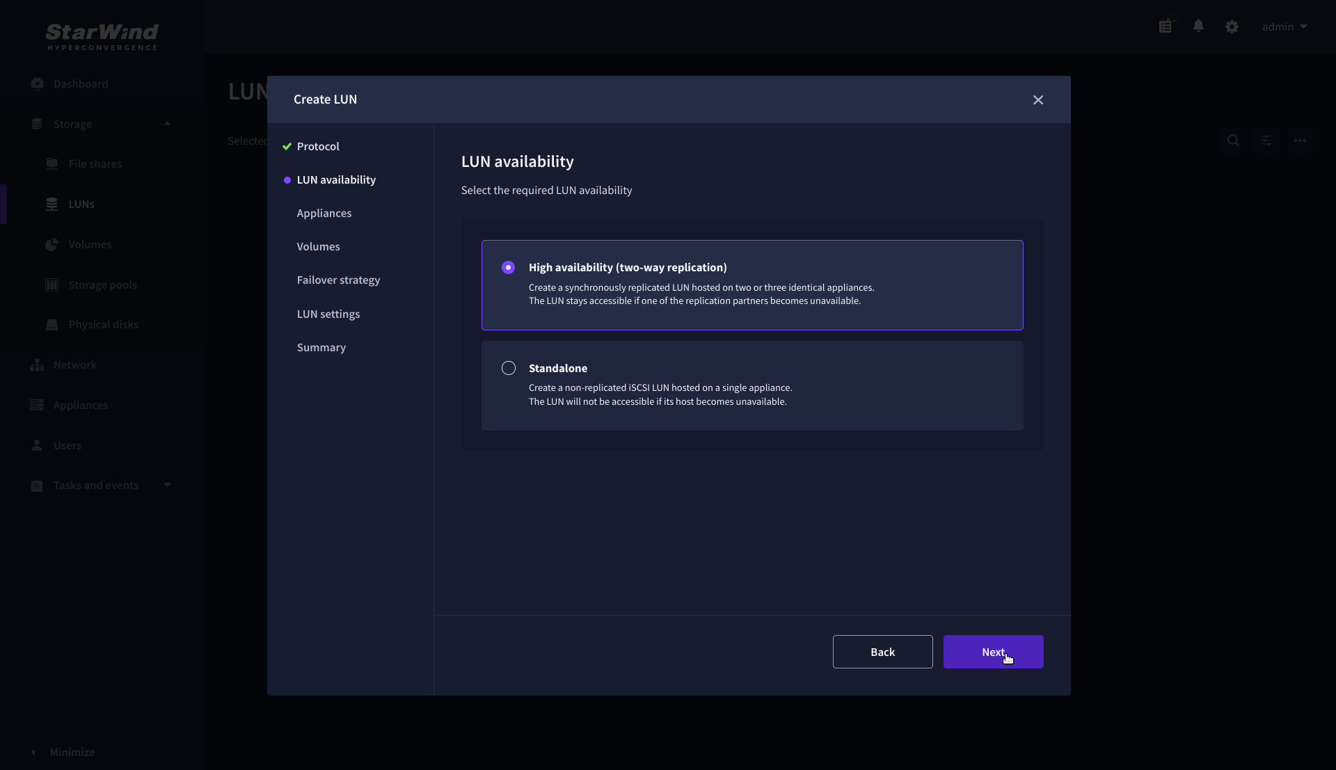
3. On the LUN availability step, select the High availability and click Next.
NOTE: The availability options for a LUN can be Standalone (without replication) or High Availability (with 2-way or 3-way replication), and are determined by the StarWind Virtual SAN license.
Below are the steps for creating a high-availability iSCSI LUN.
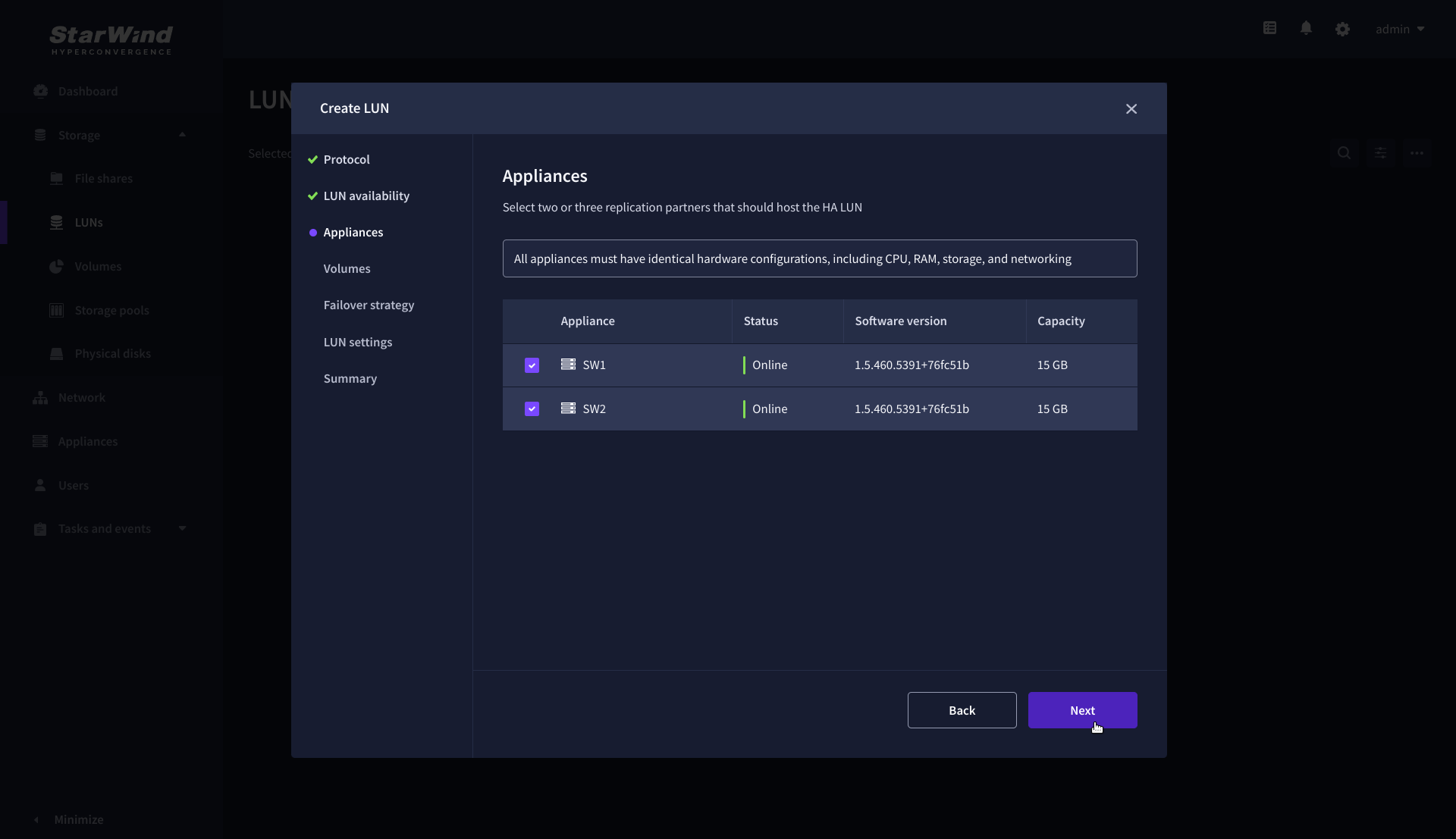
4. On the Appliances step, select partner appliances that will host new LUNs and click Next.
IMPORTANT: Selected partner appliances must have identical hardware configurations, including CPU, RAM, storage, and networking.
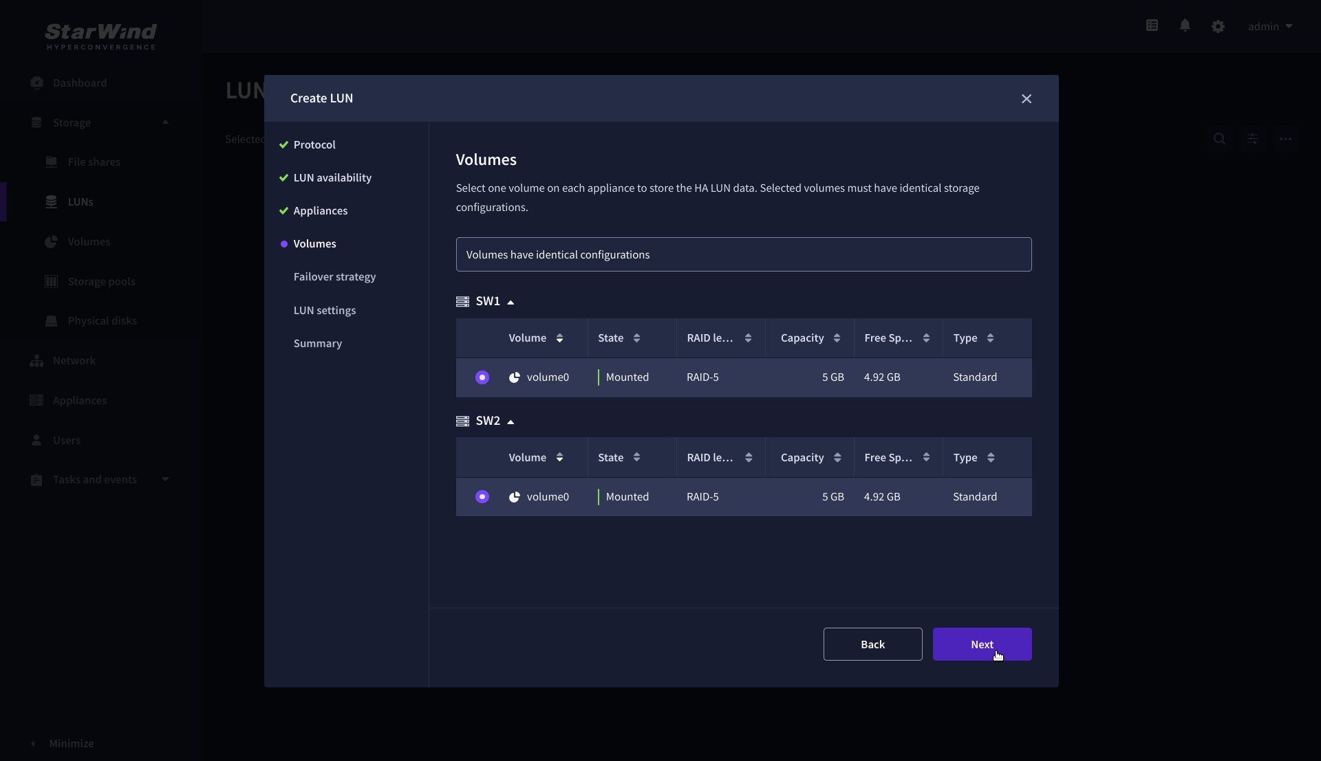
5. On the Volumes step, select the volumes for storing data on the partner appliances and click Next.
IMPORTANT: For optimal performance, the selected volumes must have identical underlying storage configurations.
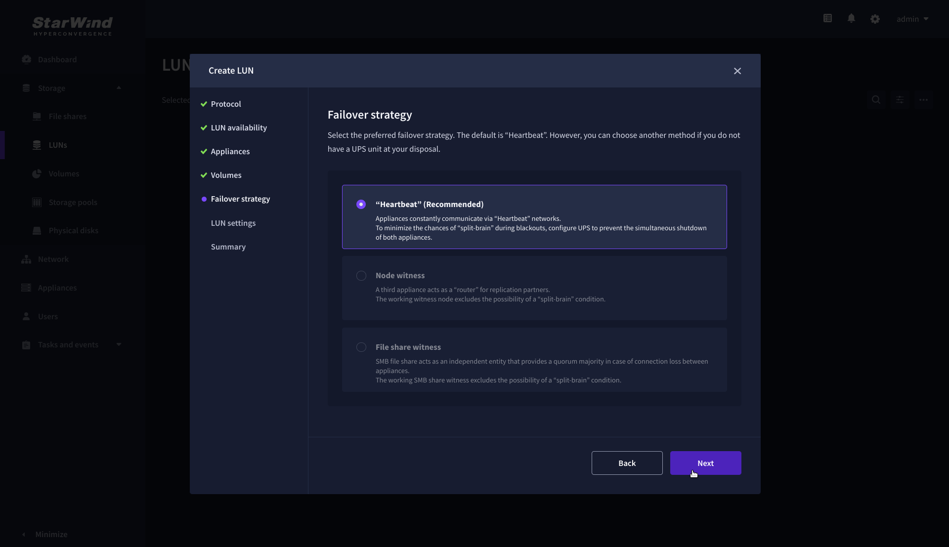
6. On the Failover strategy step, select the preferred failover strategy and click Next.
NOTE: The failover strategies for a LUN can be Heartbeat or Node Majority. In case of 2-nodes setup and None Majority failover strategy, Node witness (requires an additional third witness node), or File share witness (requires an external file share) should be configured. These options are determined by StarWind Virtual SAN license and setup configuration. Below are the steps for configuring the Heartbeat failover strategy in a two-node cluster.
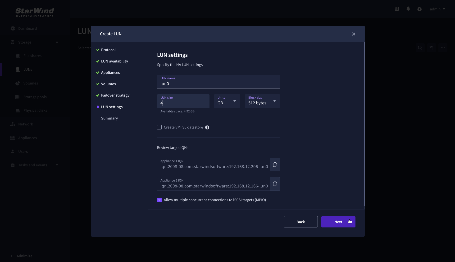
7. On the LUN settings step, specify the LUN name, size, block size, then click Next.
NOTE: For high-availability configurations, ensure that MPIO checkbox is selected.
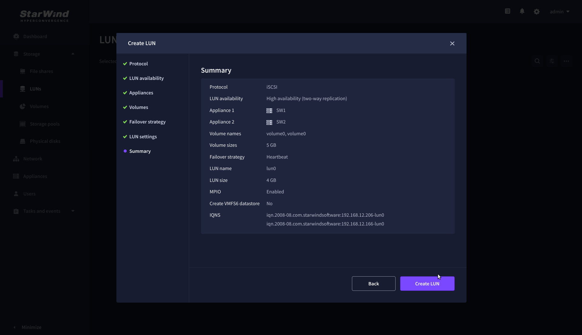
8. On the Summary step, review the LUN settings and click Create to configure new LUNs on the selected volumes.
Create HA LUN using PowerShell
This section describes how to create LUN using PowerShell. This option should be used on the setups with Free license applied. It also can be used to automate LUNs creation on the setups with Commercial, Trial, and NFR licenses applied.
To create the LUN using Web UI, please follow the steps described in the section: Create HA LUN using WebUI
The Windows machine that will be used to execute the scripts should have access to each StarWind appliance (node) over port 3261 to manage StarWind service on them.
Install PowerShell samples
1. Using WebUI, open Settings and go to the Downloads tab.
2. Click Download samples to download the installer to any Windows machine.

3. Run the downloaded installation file on Windows machine that will be used for scripts execution.
4. Choose “Install StarWindX” to install the StarWindX PowerShell IDE and sample scripts.
Creating StarWind HA LUNs using PowerShell
1. Open PowerShell ISE as Administrator.
2. Open StarWindX sample CreateHA_2.ps1 using PowerShell ISE. It can be found here: C:\Program Files\StarWind Software\StarWind\StarWindX\Samples\
NOTE: The script below creates a 1TB size 2-node HA device with a heartbeat failover strategy on StarWind nodes with management IP addresses 192.168.0.1 and 192.168.0.2 correspondingly.
The IP addresses 172.16.10.1 and 172.16.10.2 are used as heartbeat interfaces along with 192.168.0.1 and 192.168.0.2 for redundancy.
The IP addresses 172.16.20.1 and 172.16.20.2 on each node correspondingly as well as 172.16.21.1 and 172.16.21.2 are used for the devices synchronization between the nodes.
The script does not create a directory. Make sure you create the directory listed as $imagePath value before running the script.
Make sure to open 3261 and 3260 ports.
The same approach applies to CreateHA_3.ps1 which allow to create a 3-way replica HA device.
3. Configure script parameters according to the following example:
param($addr="192.168.0.1", $port=3261, $user="root", $password="starwind",
      $addr2="192.168.0.2", $port2=$port, $user2=$user, $password2=$password,
#common
      $initMethod="NotSynchronize",
      $size=1048576,
      $sectorSize=512,
      $failover=0,
      $bmpType=1,
      $bmpStrategy=0,
#primary node
      $imagePath="/mnt/sdb1/volume1",
      $imageName="device1",
      $createImage=$true,
      $storageName="",
      $targetAlias="target1",
      $poolName="pool1",
      $syncSessionCount=1,
      $aluaOptimized=$true,
      $cacheMode="none",
      $cacheSize=0,
      $syncInterface="#p2=172.16.20.2:3260,172.16.21.2:3260",
      $hbInterface="#p2=172.16.10.2:3260,192.168.0.2:3260",
      $createTarget=$true,
      $bmpFolderPath="",
#secondary node
      $imagePath2="/mnt/sdb1/volume1",
      $imageName2="device1",
      $createImage2=$true,
      $storageName2="",
      $targetAlias2="target1",
      $poolName2="pool1",
      $syncSessionCount2=1,
      $aluaOptimized2=$false,
      $cacheMode2=$cacheMode,
      $cacheSize2=$cacheSize,
      $syncInterface2="#p1=172.16.20.1:3260,172.16.21.1:3260",
      $hbInterface2="#p1=172.16.10.1:3260,192.168.0.1:3260",
      $createTarget2=$true,
      $bmpFolderPath2=""
 )

Import-Module StarWindX

try
{
	Enable-SWXLog -level SW_LOG_LEVEL_DEBUG

	$server = New-SWServer -host $addr -port $port -user $user -password $password

	$server.Connect()

	$firstNode = new-Object Node

	$firstNode.HostName = $addr
	$firstNode.HostPort = $port
	$firstNode.Login = $user
	$firstNode.Password = $password
	$firstNode.ImagePath = $imagePath
	$firstNode.ImageName = $imageName
	$firstNode.Size = $size
	$firstNode.CreateImage = $createImage
	$firstNode.StorageName = $storageName
	$firstNode.TargetAlias = $targetAlias
	$firstNode.AutoSynch = $autoSynch
	$firstNode.SyncInterface = $syncInterface
	$firstNode.HBInterface = $hbInterface
	$firstNode.PoolName = $poolName
	$firstNode.SyncSessionCount = $syncSessionCount
	$firstNode.ALUAOptimized = $aluaOptimized
	$firstNode.CacheMode = $cacheMode
	$firstNode.CacheSize = $cacheSize
	$firstNode.FailoverStrategy = $failover
	$firstNode.CreateTarget = $createTarget
	$firstNode.BitmapStoreType = $bmpType
	$firstNode.BitmapStrategy = $bmpStrategy
	$firstNode.BitmapFolderPath = $bmpFolderPath

	#
	# device sector size. Possible values: 512 or 4096(May be incompatible with some clients!) bytes.
	#
	$firstNode.SectorSize = $sectorSize

	$secondNode = new-Object Node

	$secondNode.HostName = $addr2
	$secondNode.HostPort = $port2
	$secondNode.Login = $user2
	$secondNode.Password = $password2
	$secondNode.ImagePath = $imagePath2
	$secondNode.ImageName = $imageName2
	$secondNode.CreateImage = $createImage2
	$secondNode.StorageName = $storageName2
	$secondNode.TargetAlias = $targetAlias2
	$secondNode.AutoSynch = $autoSynch2
	$secondNode.SyncInterface = $syncInterface2
	$secondNode.HBInterface = $hbInterface2
	$secondNode.SyncSessionCount = $syncSessionCount2
	$secondNode.ALUAOptimized = $aluaOptimized2
	$secondNode.CacheMode = $cacheMode2
	$secondNode.CacheSize = $cacheSize2
	$secondNode.FailoverStrategy = $failover
	$secondNode.CreateTarget = $createTarget2
	$secondNode.BitmapFolderPath = $bmpFolderPath2

	$device = Add-HADevice -server $server -firstNode $firstNode -secondNode $secondNode -initMethod $initMethod

	while ($device.SyncStatus -ne [SwHaSyncStatus]::SW_HA_SYNC_STATUS_SYNC)
	{
		$syncPercent = $device.GetPropertyValue("ha_synch_percent")
	        Write-Host "Synchronizing: $($syncPercent)%" -foreground yellow

		Start-Sleep -m 2000

		$device.Refresh()
	}
}
catch
{
	Write-Host $_ -foreground red
}
finally
{
	$server.Disconnect()
}
Detailed explanation of script parameters:
-addr, -addr2 — partner nodes IP address.
Format: string. Default value: 192.168.0.1, 192.168.0.2
allowed values: localhost, IP-address
-port, -port2 — local and partner node port.
Format: string. Default value: 3261
-user, -user2 — local and partner node user name.
Format: string. Default value: root
-password, -password2 — local and partner node user password.
Format: string. Default value: starwind
#common
-initMethod – set the initial synchronization option.
Format: string.
Values:
Clear – default
NotSynchronize – skips synchronization (works ONLY IF THERE IS NO DATA TO SKIP THE ORIGINAL SYNCHRONIZATION).
SyncFromFirst or SyncFromSecond or SyncFromThird – runs full synchronization from the specific node. Use it for recreating replicas.
-size – set size for HA-device (in MB)
Format: integer. Default value: 12
-sectorSize – set sector size for HA-device
Format: integer. Default value: 512
allowed values: 512, 4096
-failover – set type failover strategy
Format: integer. Default value: 0 (Heartbeat)
allowed values: 0, 1 (Node Majority)
-bmpType – set bitmap type, is set for both partners at once
Format: integer. Default value: 1 (RAM)
allowed values: 1, 2 (DISK)
-bmpStrategy – set journal strategy, is set for both partners at once
Format: integer. Default value: 0
allowed values: 0, 1 – Best Performance (Failure), 2 – Fast Recovery (Continuous)
-storageName is used only if you plan to add the partner to the existing device. For CreateHA_2.ps1 use, leave it as is.
#primary node
-imagePath – set path to store the device file
Format: string. Default value: My computer\C\starwind”. For Linux the following format should be used: “VSA Storage\mnt\mount_point”
-imageName – set name device
Format: string. Default value: masterImg21
-createImage – set create image file
Format: boolean. Default value: true
-targetAlias – set alias for target
Format: string. Default value: targetha21
-poolName – set storage pool. Do not change it and keep default value.
Format: string. Default value: pool1
-aluaOptimized – set Alua Optimized
Format: boolean. Default value: true
-cacheMode – set type L1 cache (optional parameter)
Format: string. Default value: wb
allowed values: none, wb, wt
-cacheSize – set size for L1 cache in MB (optional parameter)
Format: integer. Default value: 128
allowed values: 1 and more
-syncInterface – set sync channel IP-address from partner node
Format: string. Default value: “#p2={0}:3260”
-hbInterface – set heartbeat channel IP-address from partner node
Format: string. Default value: “”
-createTarget – set creating target
Format: string. Default value: true
Even if you do not specify the parameter -createTarget, the target will be created automatically.
If the parameter is set as -createTarget $false, then an attempt will be made to create the device with existing targets, the names of which are specified in the -targetAlias (targets must already be created)
-bmpFolderPath – set path to save bitmap file
Format: string.
#secondary node
-imagePath2 – set path to store the device file
Format: string. Default value: “My computer\C\starwind”. For Linux the following format should be used: “VSA Storage\mnt\mount_point”
-imageName2 – set name device
Format: string. Default value: masterImg21
-createImage2 – set create image file
Format: boolean. Default value: true
-targetAlias2 – set alias for targetFormat: string.
Default value: targetha22
-poolName2 – set storage pool. Do not change it and keep default value.
Format: string. Default value: pool1
-aluaOptimized2 – set Alua Optimized
Format: boolean. Default value: true
-cacheMode2 – set type L1 cache (optional parameter)
Format: string. Default value: wb
allowed values: wb, wt
-cacheSize2 – set size for L1 cache in MB (optional parameter)
Format: integer. Default value: 128
allowed values: 1 and more
-syncInterface2 – set sync channel IP-address from partner node
Format: string. Default value: “#p1={0}:3260”
-hbInterface2 – set heartbeat channel IP-address from partner node
Format: string. Default value: “”
-createTarget2 – set creating target
Format: string. Default value: true
Even if you do not specify the parameter -createTarget, the target will be created automatically.If the parameter is set as -createTarget $false, then an attempt will be made to create the device with existing targets, the names of which are specified in the -targetAlias (targets must already be created)
-bmpFolderPath2 – set path to save bitmap file
Format: string.
IMPORTANT: If the script should be executed again with the same parameters, (for example, the first time execution has failed) make sure to do the following for one node at a time before the next attempt to execute the script:
1. Stop StarWind Service:
sudo systemctl stop starwind-virtual-san2. Go to /opt/starwind/starwind-virtual-san/drive_c/starwind/headers and delete the headers you do not need.
3. Go to the underlying storage specified as $imagePath and delete the header and imagefile there.
4. Go to the folder with StarWind.cfg (/opt/starwind/starwind-virtual-san/drive_c/starwind/StarWind.cfg ) and copy it.
5. Edit StarWind.cfg:
sudo nano /opt/starwind/starwind-virtual-san/drive_c/starwind/StarWind.cfg6. Navigate under <targets>, remove target you do not need.
7. Navigate under <devices>, and remove the device entry you do not need.
8. Start the service:
sudo systemctl start starwind-virtual-san9. Wait for the devices synchronization.
10. Repeat for the remaining StarWind VSAN instance.
Connecting and Provisioning StarWind HA Storage on Windows Server Hosts
The sections below describe how to discover and connect iSCSI targets, presented by StarWind VSAN services on
different nodes, on Windows servers. In order to get the redundant storage connection, each target from each
StarWind node should be connected on each cluster node.
If there is a need to make multiple iSCSI connections in Windows the parameter
iScsiDiscoveryListInterfaces in StarWind configuration file should be set to 1. Follow the steps
below to edit the StarWind.cfg:
1. Using StarWind WebUI, confirm that StarWind devices are synchronized on all nodes.
2. Using WebUI, enable SSH on the node (Settings->Services->Select SSH service and press
Start).
3. Connect to the StarWind CVM using an SSH terminal (e.g., PuTTY).
4. Stop StarWindService for one node via the SSH terminal.
sudo systemctl stop starwind-virtual-san 5. Locate the StarWind configuration file:
/opt/starwind/starwind-virtual-san/drive_c/starwind/StarWind.cfg
6. Copy StarWind.cfg to make a backup.
7. Edit StarWind.cfg and change the parameter iScsiDiscoveryListInterfaces to 1.
sudo nano /opt/starwind/starwind-virtual-san/drive_c/starwind/StarWind.cfg8. Start StarWindService:
sudo systemctl start starwind-virtual-san 9. Wait for fast synchronization to complete.
10. Repeat for the remaining nodes.
2-Node: Provisioning StarWind HA Storage to Windows Server Hosts
Discovery of StarWind iSCSI targets on Windows Server hosts
1. Open Start/Search and type “iSCSI Initiator” to Launch Microsoft iSCSI Initiator. Alternatively, start Command Prompt (CMD) and execute the following command:
iscsicpl
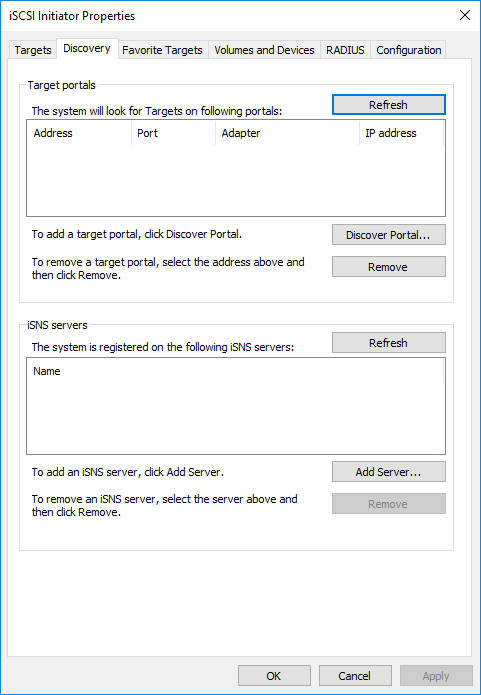
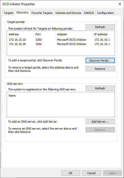
2. In the iSCSI Initiator Properties window, navigate to the Discovery tab and click Discover Portal…
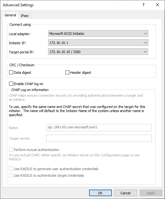
3. In the Discover Target Portal window, enter the IP address of the first StarWind Appliance’s Data network interface (for example, appliance “SW1” with the IP address 172.16.10.10), then click Advanced…
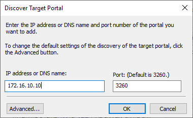
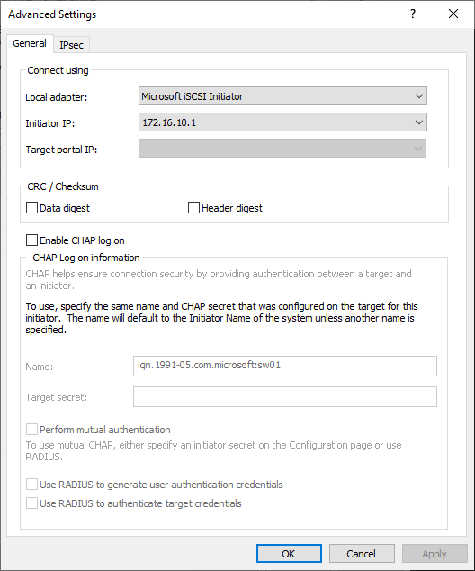
4. In the Advanced Settings window, under the Connect using section, select Microsoft iSCSI Initiator as the Local adapter. Then, select the IP address of the Data/Heartbeat network of the current Windows Server host as the Initiator IP, and click Apply.
5. In the Discovery tab, click Discover Portal…

6. In the Discover Target Portal window, enter the IP address of the second StarWind Appliance’s Data network interface (for example, appliance “SW2” with the IP address 172.16.10.20), then click Advanced…
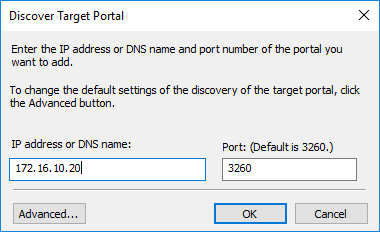
7. In the Advanced Settings window, under the Connect using section, select Microsoft iSCSI Initiator as the Local adapter. Then, select the IP address of the Data/Heartbeat network of the current Windows Server host as the Initiator IP, and click Apply.
8. Now, all iSCSI target portals have been added to the first Windows Server host.
9. Repeat the steps 1-8 on the partner node.
Connecting StarWind iSCSI targets to Windows Server hosts
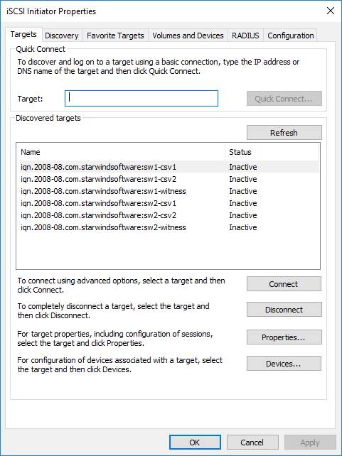
1. Click the Targets tab. The previously created targets are listed in the Discovered Targets section.
NOTE: If the created targets are not listed, check the firewall settings of the StarWind Server as well as the list of networks served by the StarWind Server (go to StarWind Management Console -> Configuration -> Network). Alternatively, check the Access Rights tab in StarWind Management Console for any restrictions.
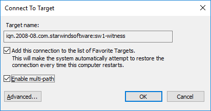
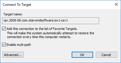
2. Select the Witness target from the local server and click Connect.
3. Enable checkboxes as shown in the image below. Click Advanced.
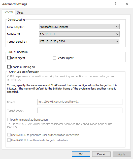
4. Select Microsoft iSCSI Initiator in the Local adapter dropdown menu. In the Initiator IP field, select the IP address for the Data network. In the Target portal IP, select the portal IP from the same subnet. Confirm the actions.
5. Repeat the steps 2-4 to connect the Witness target from the partner node.
Advanced settings should look like in the picture below with the target portal IP 172.16.10.20:
6. Select the CSV1 target discovered from the local server and click Connect.
7. Enable checkboxes as shown in the image below. Click Advanced.
8. Select Microsoft iSCSI Initiator in the Local adapter dropdown menu. In Target portal IP, select 172.16.10.10. Confirm the actions.
9. Select the CSV1 target from the partner StarWind node and click Connect.
10. Enable checkboxes Add this connection to the list of Favorite Targets… and Enable multi-path. Click Advanced.
11. Select Microsoft iSCSI Initiator in the Local adapter dropdown menu. In the Initiator IP field, select the IP address for the Data network. In the Target portal IP, select the portal IP from the same subnet. Confirm the actions.
12. Repeat the steps 1-11 for all remaining HA device targets.
13. Repeat steps 1-12 on the other StarWind node, specifying corresponding Data network IP addresses.
NOTE: Multiple (2,3 or 4) identical iSCSI connections to the same target might be configured depending on the network throughput used for Data and Replication, underlying storage performance, or CPU performance.
Configuring Multipath
It is recommended to configure the different MPIO policies depending on iSCSI channel throughput. It is recommended to set Least Queue Depth MPIO load balancing policy.
NOTE: Different MPIO policies can be set depending on the network throughput, storage performance or setup peculiarities.
1. Configure the MPIO policy for each target with the load balance policy of choice. Select the Target located on the local server and click Devices.
2. In the Devices dialog, click MPIO.
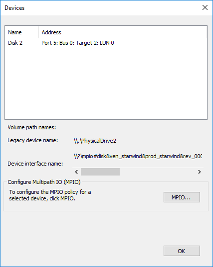
3. Select the appropriate load balancing policy.
4. Repeat the steps 1-3 for configuring the MPIO policy for each remaining device on the current node and on the partner node.
Connecting Disks to Servers
1. Open the Disk Management snap-in. The StarWind disks will appear as unallocated and offline.

2. Bring the disks online by right-clicking on them and selecting the Online menu option.
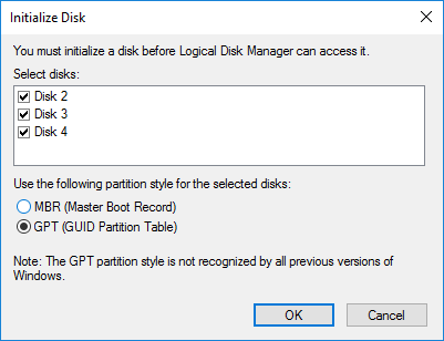
3. Select the CSV disk (check the disk size to be sure) and right-click on it to initialize.
4. By default, the system will offer to initialize all non-initialized disks. Use the Select Disks area to choose the disks. Select GPT (GUID Partition Style) for the partition style to be applied to the disks. Press OK to confirm.
5. Right-click on the selected disk and choose New Simple Volume.
6. In New Simple Volume Wizard, indicate the volume size. Click Next.
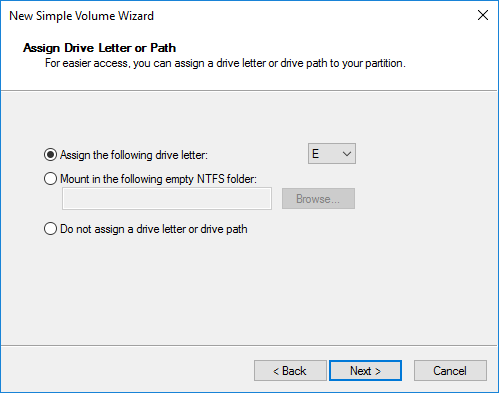
7. Assign a drive letter to the disk. Click Next.
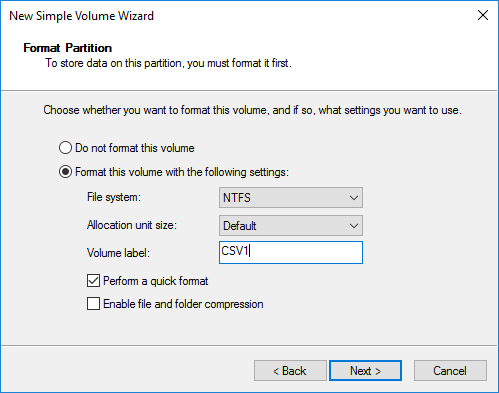
8. Select NTFS in the File System dropdown menu. Keep Allocation unit size as Default. Set the Volume Label of choice. Click Next.
9. Press Finish to complete.
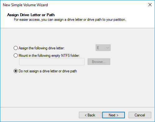
10. Complete the steps 1-9 for the Witness disk. Do not assign any drive letter or drive path for it.
11. On the partner node, open the Disk Management snap-in. All StarWind disks will appear offline. If the status is different from the one shown below, click Action->Refresh in the top menu to update the information about the disks.
12. Repeat steps from the 2nd to bring all the remaining StarWind disks online.
Creating a Failover Cluster in Windows Server
NOTE: To avoid issues during the cluster validation configuration, it is recommended to install the latest Microsoft updates on each node.
NOTE: Server Manager can be opened on the server with desktop experience enabled (necessary features should be installed). Alternatively, the Failover cluster can be managed with Remote Server Administration Tools:
https://docs.microsoft.com/en-us/windows-server/remote/remote-server-administration-tools
NOTE: For converged deployment (SAN & NAS running as a dedicated storage cluster) the Microsoft Failover Cluster is deployed on separate computing nodes. Additionally, for the converged deployment scenario, the storage nodes that host StarWind SAN & NAS as CVM or bare metal do not require a domain controller and Failover Cluster to operate.
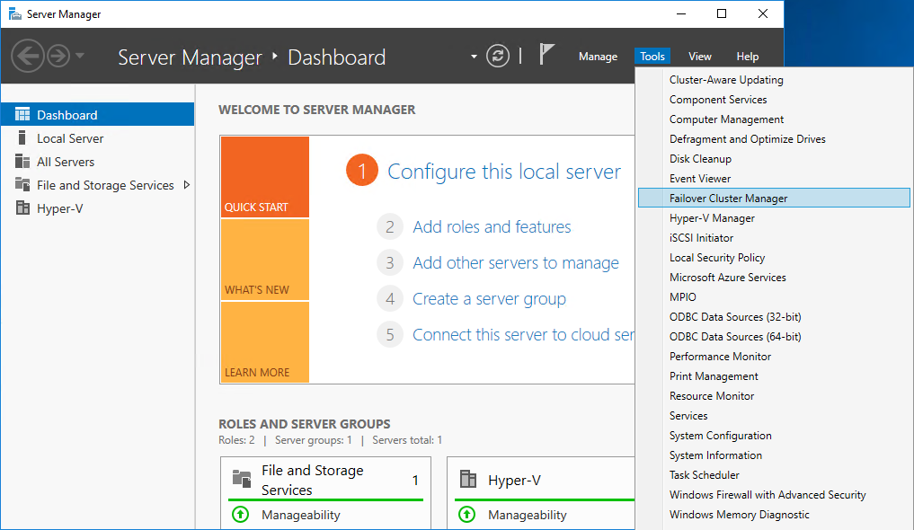
1. Open Server Manager. Select the Failover Cluster Manager item from the Tools menu.
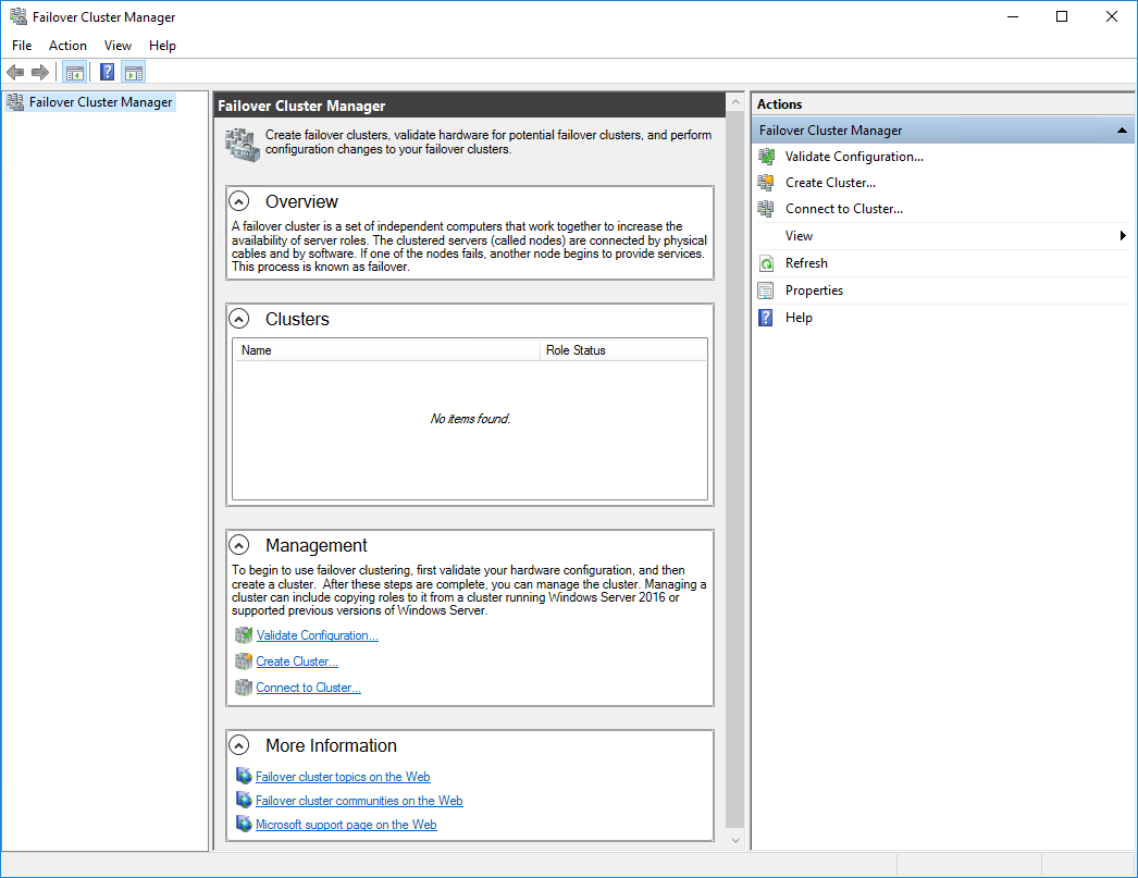
2. Click the Create Cluster link in the Actions section of Failover Cluster Manager.
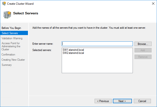
3. Specify the servers to be added to the cluster. Click Next to continue.
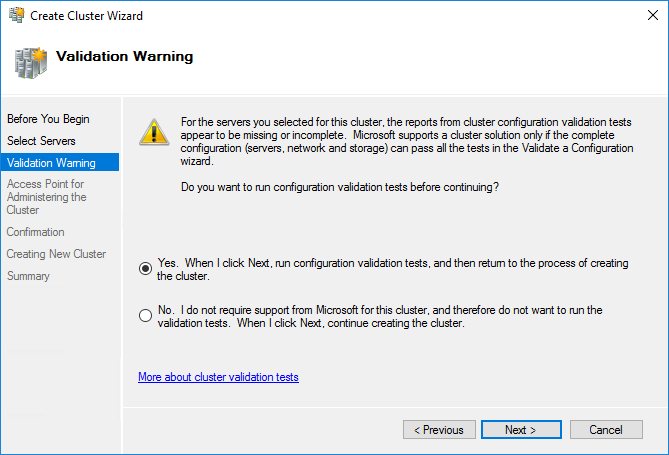
4. Validate the configuration by running the cluster validation tests: select Yes… and click Next to continue.
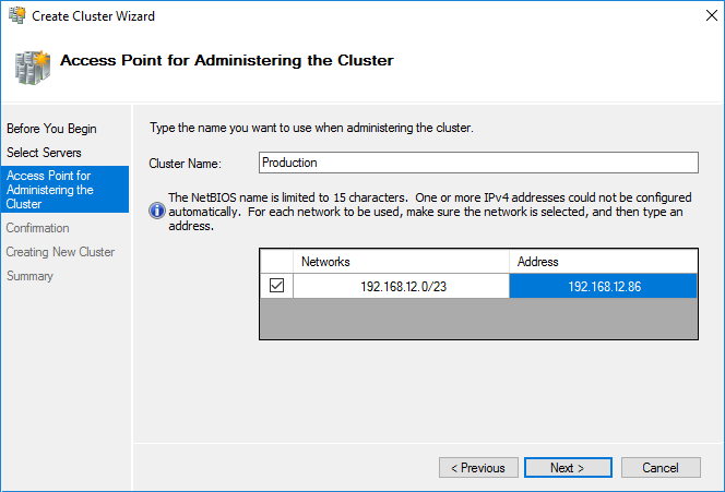
5. Specify the cluster name.
NOTE: If the cluster servers get IP addresses over DHCP, the cluster also gets its IP address over DHCP. If the IP addresses are set statically, set the cluster IP address manually.
6. Make sure that all settings are correct. Click Previous to make any changes or Next to proceed.
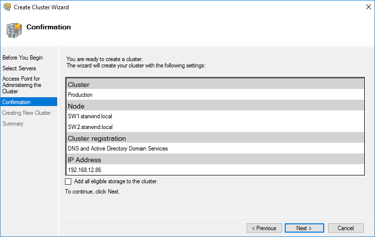
NOTE: If checkbox Add all eligible storage to the cluster is selected, the wizard will add all disks to the cluster automatically. The device with the smallest storage volume will be assigned as a Witness. It is recommended to uncheck this option before clicking Next and add cluster disks and the Witness drive manually.
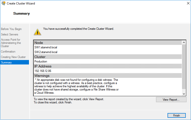
7. The process of the cluster creation starts. Upon the completion, the system displays the summary with the detailed information. Click Finish to close the wizard.
Adding Storage to the Cluster
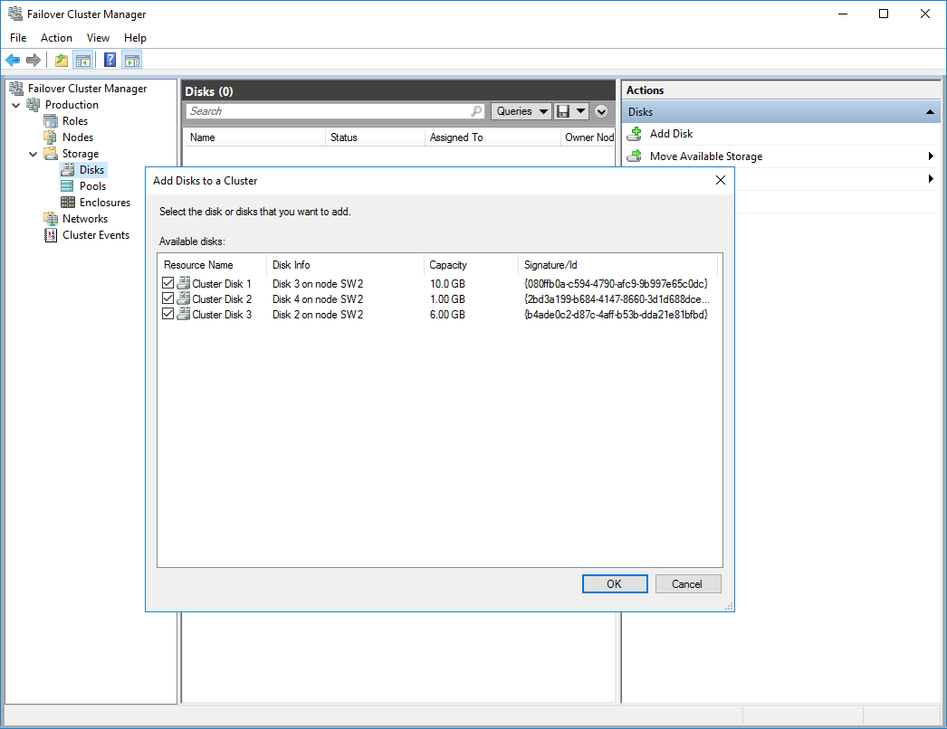
1. In Failover Cluster Manager, navigate to Cluster -> Storage -> Disks. Click Add Disk in the Actions panel, choose StarWind disks from the list and confirm the selection.
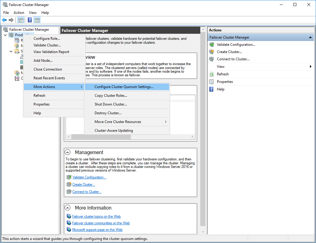
2. To configure the cluster witness disk, right-click on Cluster and proceed to More Actions -> Configure Cluster Quorum Settings.
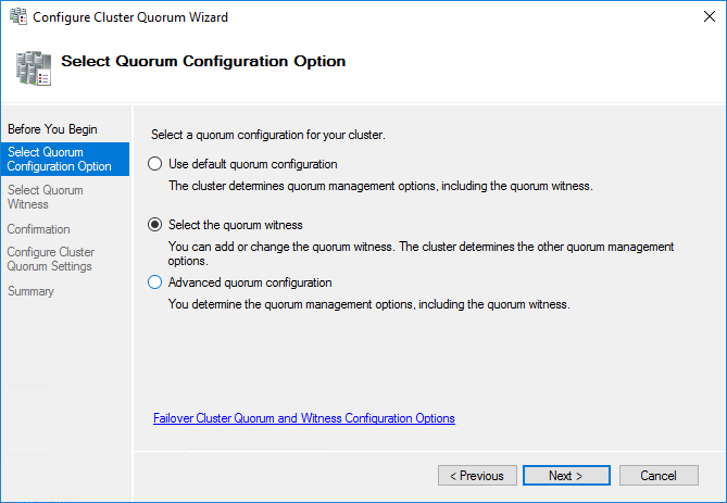
3. Follow the wizard and use the Select the quorum witness option. Click Next.
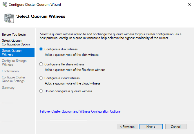
4. Select Configure a disk witness. Click Next.
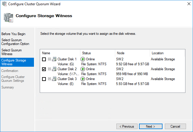
5. Select the Witness disk to be assigned as the cluster witness disk. Click Next and press Finish to complete the operation.
6. In Failover Cluster Manager, Right-click the disk and select Add to Cluster Shared Volumes.
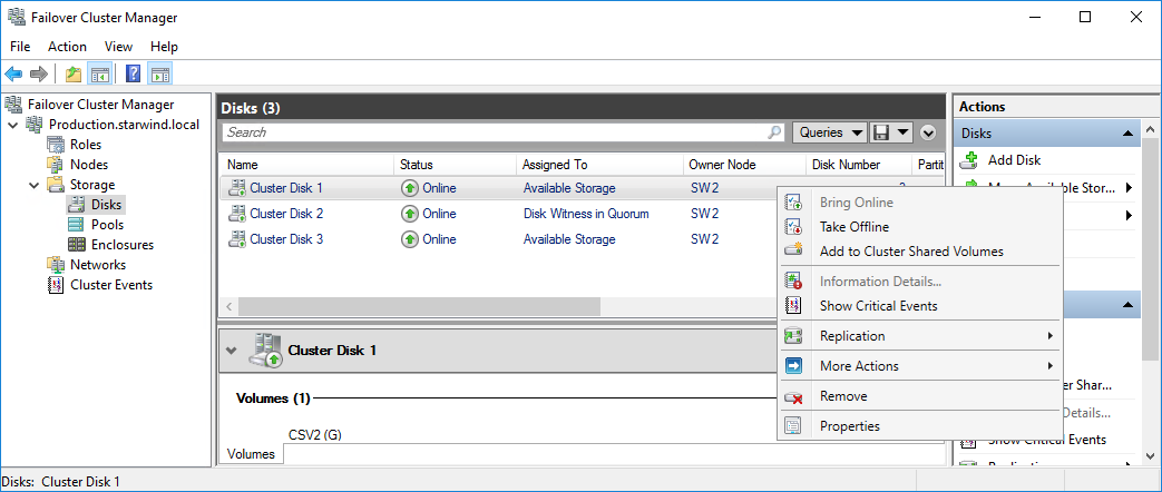
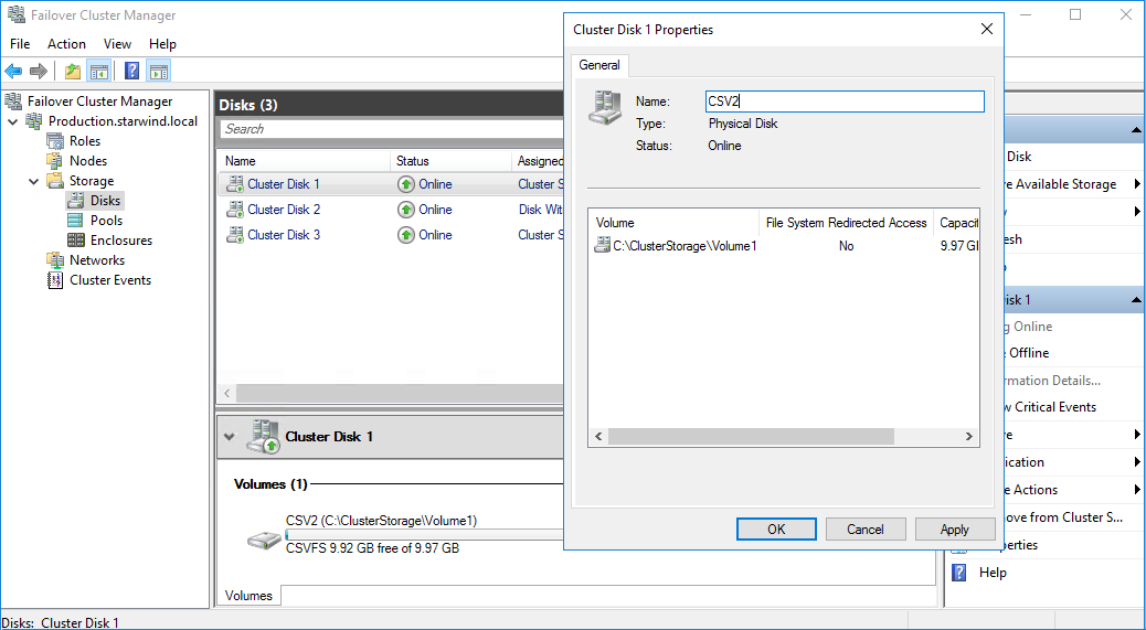
7. If renaming of the cluster shared volume is required, right-click on the disk and select Properties. Type the new name for the disk and click Apply followed by OK.
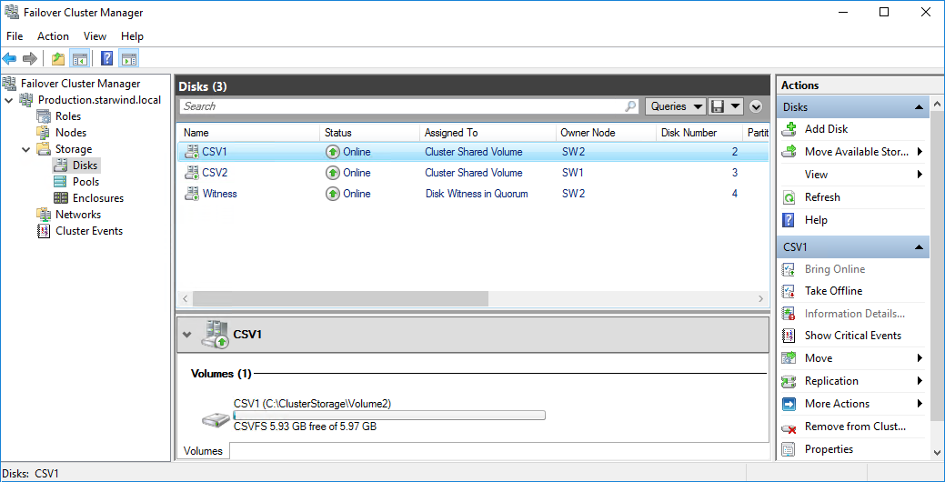
8. Perform the steps 6-7 for any other disk in Failover Cluster Manager. The resulting list of disks will look similar to the screenshot below.
Configuring Cluster Network Preferences
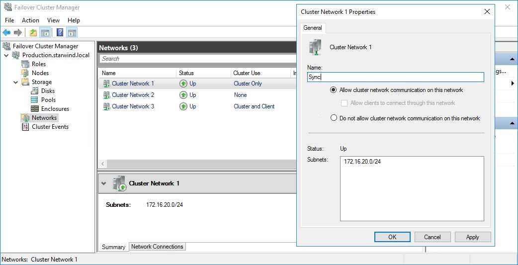
1. In the Networks section of the Failover Cluster Manager, right-click on the network from the list. Set its new name if required to identify the network by its subnet. Apply the change and press OK.
NOTE: Double-check that cluster communication is configured with redundant networks:
https://docs.microsoft.com/en-us/windows-server/failover-clustering/smb-multichannel
2. Rename other networks as described above, if required.
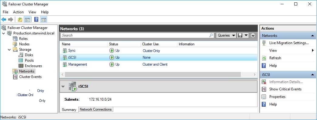
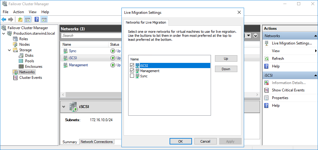
3. In the Actions tab, click Live Migration Settings. Uncheck the synchronization network, while the iSCSI network can be used if it is 10+ Gbps. Apply the changes and click OK.
The cluster configuration is completed and it is ready for virtual machines deployment. Select Roles and in the Action tab, click Virtual Machines -> New Virtual Machine. Complete the wizard.
Installing File Server Roles
Please follow the steps below if file shares configuration is required
Scale-Out File Server (SOFS) for application data
1. Open Server Manager: Start -> Server Manager.
2. Select: Manage -> Add Roles and Features.
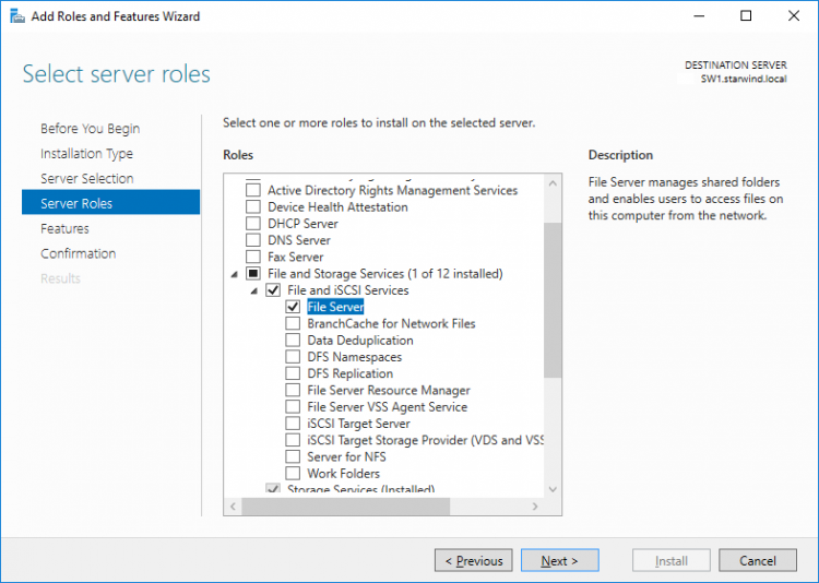
3. Follow the installation wizard steps to install the roles selected in the screenshot below:
4. Restart the server after installation is completed and perform steps above on the each server.
File Server for general use with SMB share
1. Open Server Manager: Start -> Server Manager.
2. Select: Manage -> Add Roles and Features.
3. Follow the installation wizard steps to install the roles selected in the screenshot below:
4. Restart the server after installation is completed and perform steps above on each server.
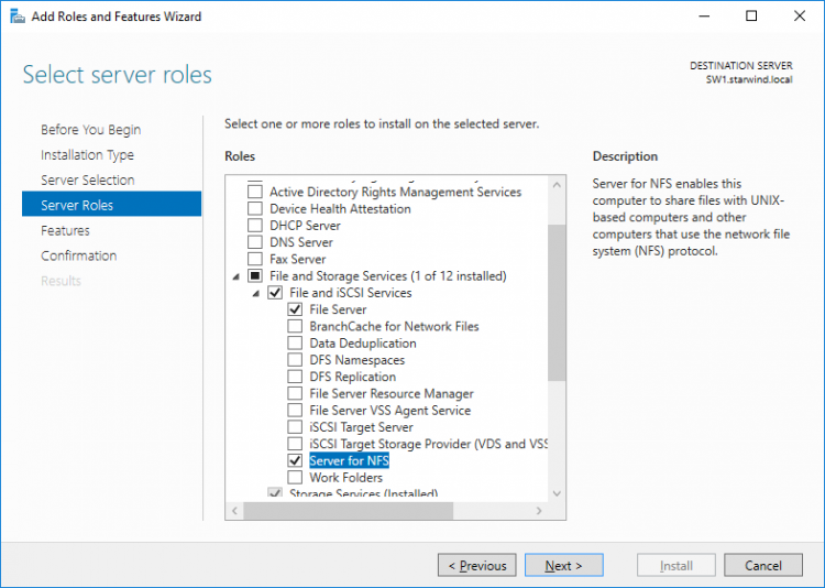
File Server for general use with NFS share
1. Open Server Manager: Start -> Server Manager.
2. Select: Manage -> Add Roles and Features.
3. Follow the installation wizard steps to install the roles selected in the screenshot below:
4. Restart the server after installation is completed and perform steps above on each server.
Configuring File Shares
Please follow the steps below if file shares should be configured on cluster nodes.
Configuring the Scale-Out File Server Role
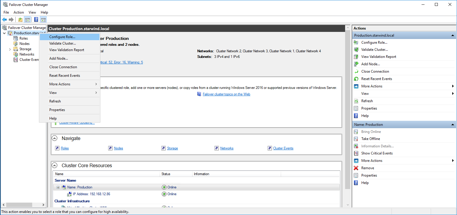
1. To configure the Scale-Out File Server Role, open Failover Cluster Manager.
2. Right-click the cluster name, then click Configure Role and click Next to continue.
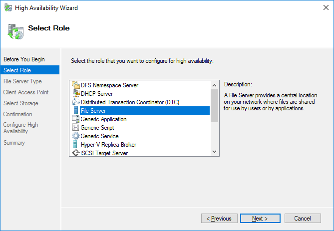
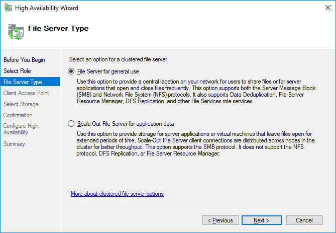
3. Select the File Server item from the list in High Availability Wizard and click Next to continue.
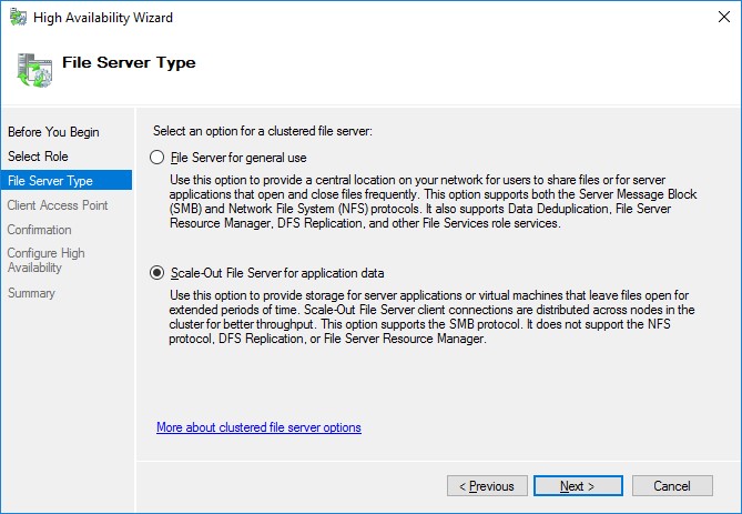
4. Select Scale-Out File Server for application data and click Next.
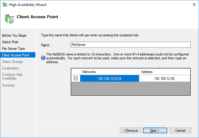
5. On the Client Access Point page, in the Name text field, type the NetBIOS name that will be used to access a Scale-Out File Server.
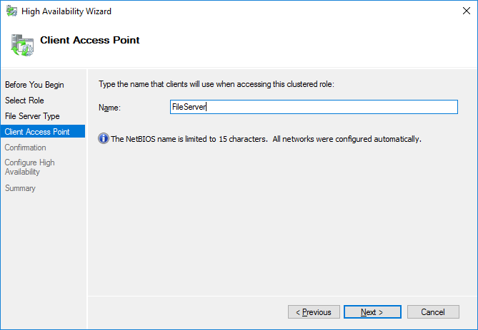
Click Next to continue.
6. Check whether the specified information is correct. Click Next to continue or Previous to change the settings.
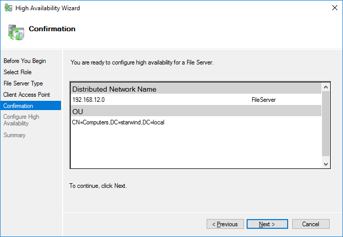
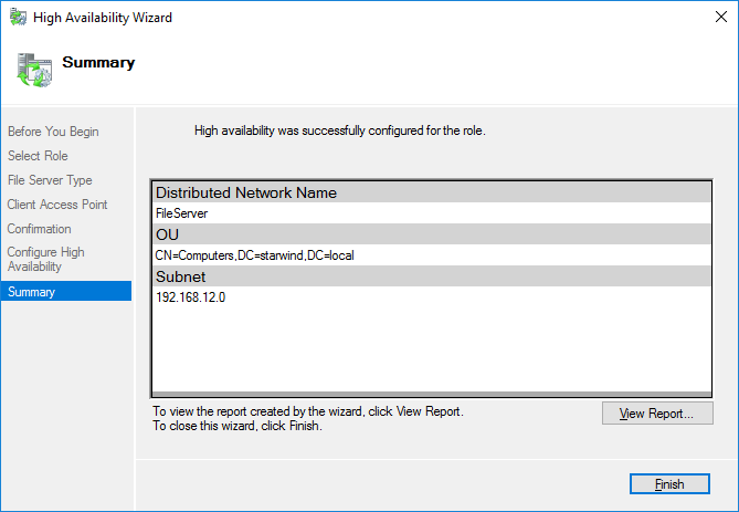
7. Once the installation is finished successfully, the Wizard should now look like the screenshot below.
Click Finish to close the Wizard.
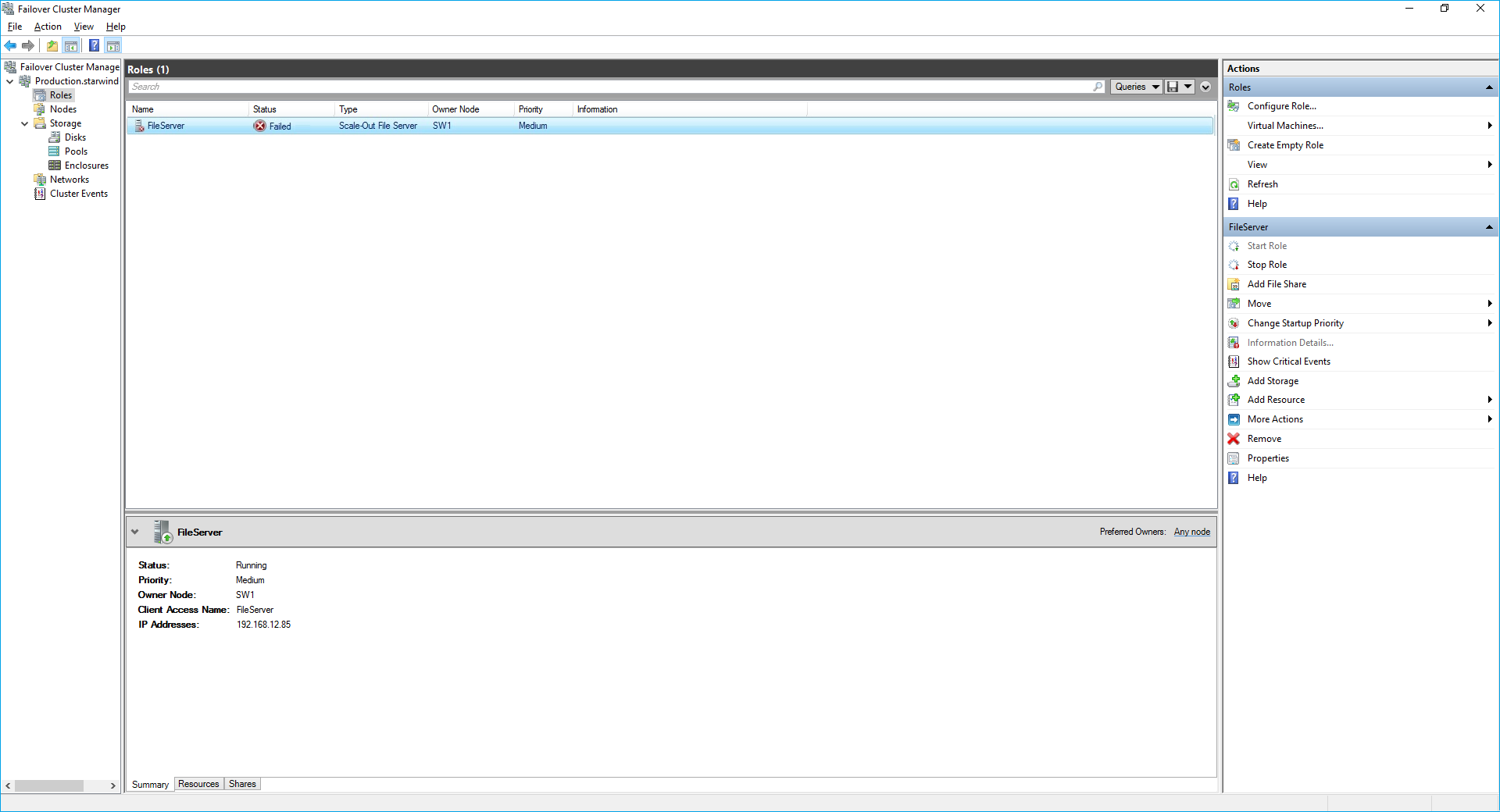
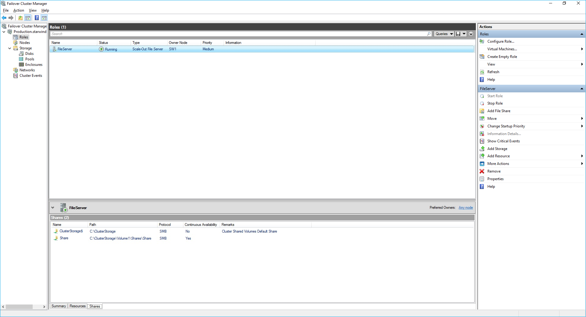
8. The newly created role should now look like the screenshot below.

NOTE: If the role status is Failed and it is unable to Start, please, follow the next steps:
- open Active Directory Users and Computers
- enable the Advanced view if it is not enabled
- edit the properties of the OU containing the cluster computer object (in this case – Production)
- open the Security tab and click Advanced
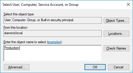
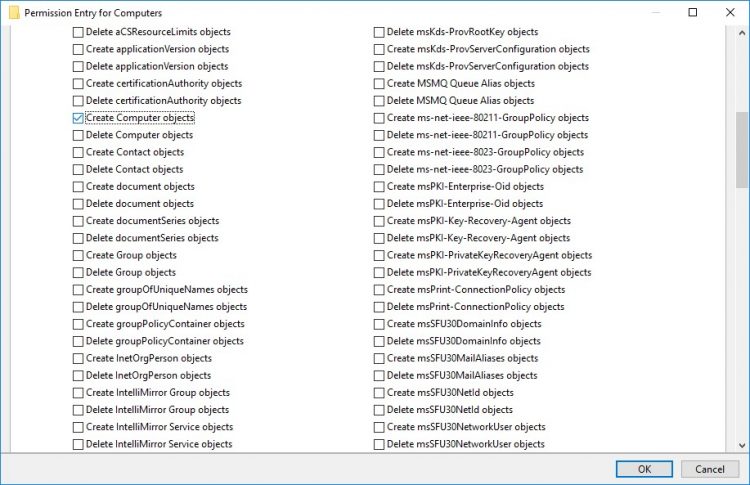
- in the appeared window, press Add (the Permission Entry dialog box opens), click Select a principal
- in the appeared window, click Object Types, select Computers, and click OK
- enter the name of the cluster computer object (in this case – Production)
- go back to Permission Entry dialog, scroll down, and select Create Computer Objects,
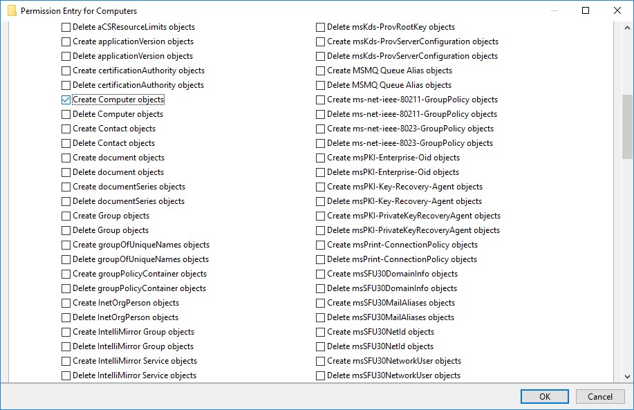
- click OK on all opened windows to confirm the changes
- open Failover Cluster Manager, right-click SOFS role and click Start Role
Configuring File Share
To Add File Share:
- open Failover Cluster Manager
- expand the cluster and then click Roles
- right-click the file server role and then press Add File Share
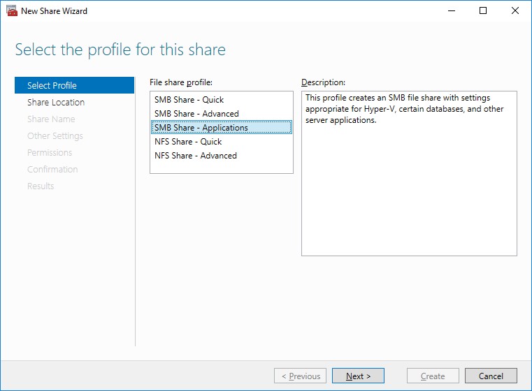
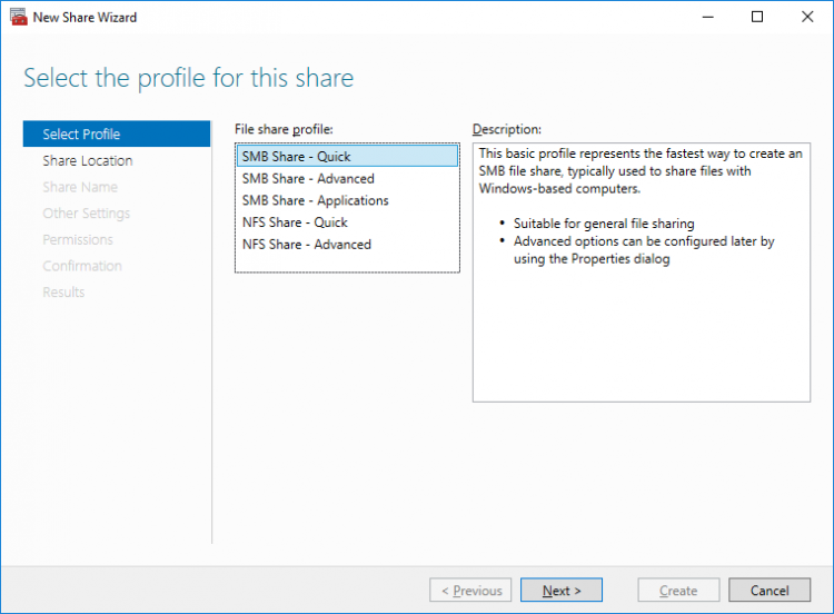
- on the Select the profile for this share page, click SMB Share – Applications and then click Next
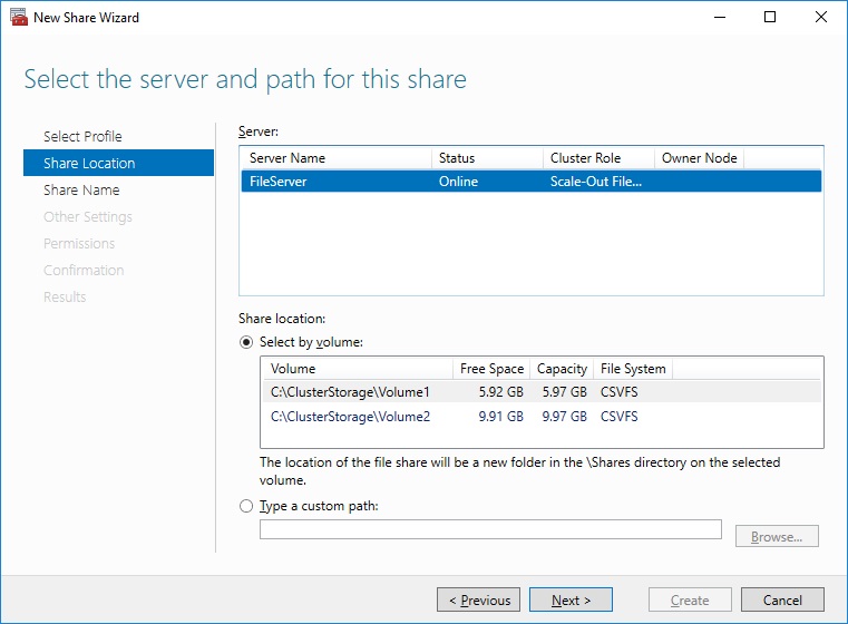
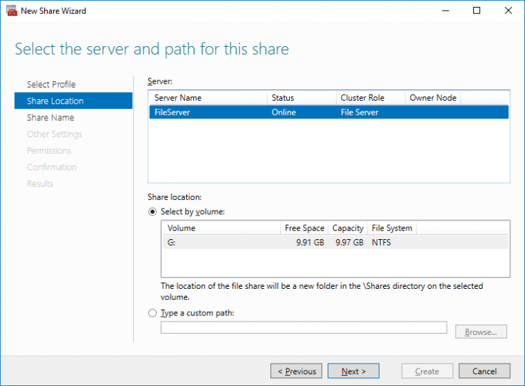
5. Select a CSV to host the share. Click Next to proceed.
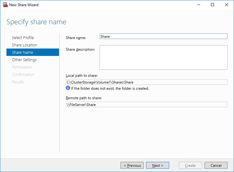
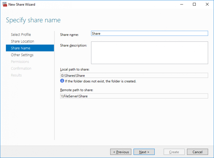
6. Type in the file share name and click Next.
7. Make sure that the Enable Continuous Availability box is checked. Click Next to proceed.
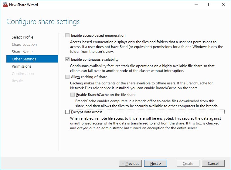
8. Specify the access permissions for the file share.
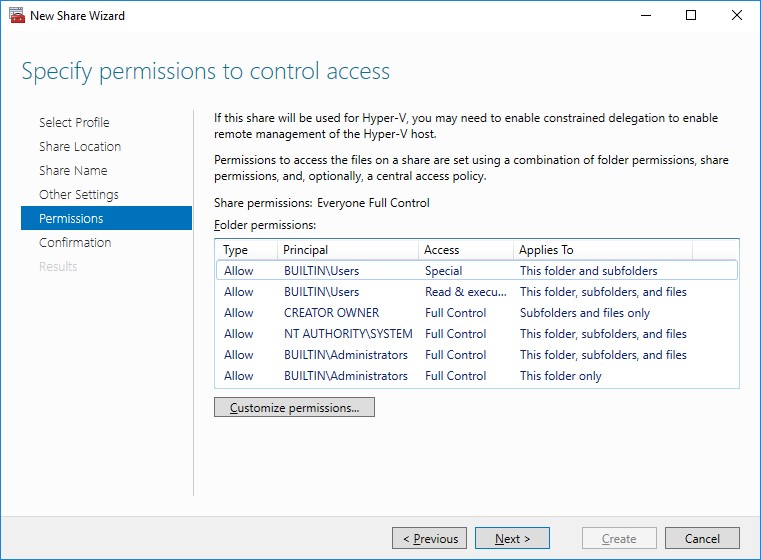
NOTE:
- for the Scale-Out File Server for Hyper-V, all Hyper-V computer accounts, the SYSTEM account, and all Hyper-V administrators must be provided with the full control on the share and file system
- for the Scale-Out File Server on Microsoft SQL Server, the SQL Server service account must be granted full control on the share and the file system
9. Check whether specified settings are correct. Click Previous to make any changes or click Create to proceed.
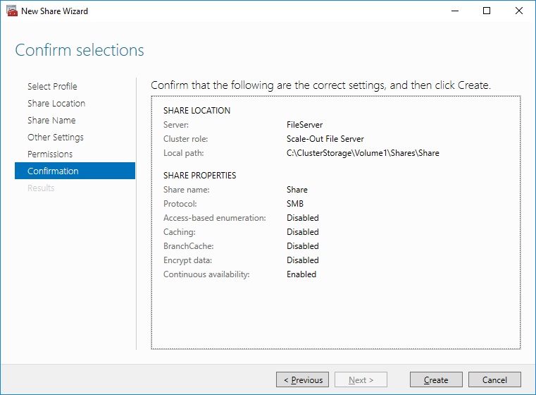
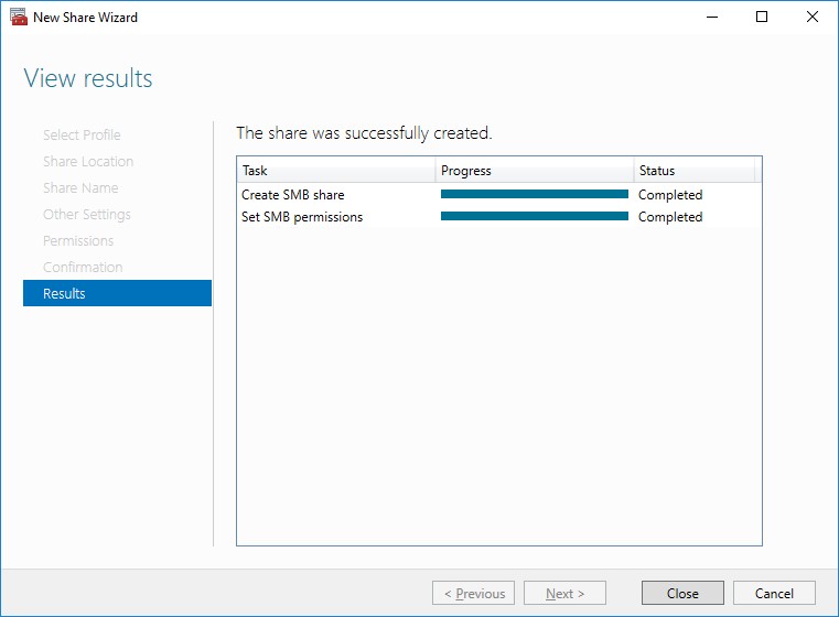
10. Check the summary and click Close to close the Wizard.
To Manage Created File Shares:
- open Failover Cluster Manager
- expand the cluster and click Roles
- choose the file share role, select the Shares tab, right-click the created file share, and select Properties:
Configuring the File Server for General Use Role
NOTE: To configure File Server for General Use, the cluster should have available storage
1. To configure the File Server for General Use role, open Failover Cluster Manager.
2. Right-click on the cluster name, then click Configure Role and click Next to continue.
3. Select the File Server item from the list in High Availability Wizard and click Next to continue.
4. Select File Server for general use and click Next.
5. On the Client Access Point page, in the Name text field, type the NETBIOS name that will be used to access the File Server and IP for it.
Click Next to continue.
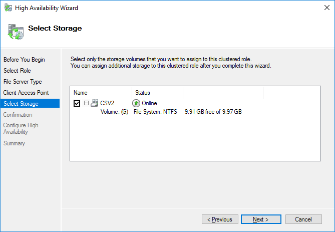
6. Select the Cluster disk and click Next.
7. Check whether the specified information is correct. Click Next to proceed or Previous to change the settings.
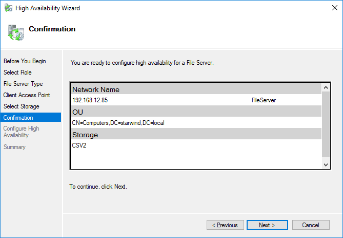
8. Once the installation has been finished successfully, the Wizard should now look like the screenshot below.
Click Finish to close the Wizard.
9. The newly created role should now look like the screenshot below.

NOTE: If the role status is Failed and it is unable to Start, please, follow the next steps:
- open Active Directory Users and Computers
- enable the Advanced view if it is not enabled
- edit the properties of the OU containing the cluster computer object (in this case – Production)
- open the Security tab and click Advanced
- in the appeared window, press Add (the Permission Entry dialog box opens), click Select a principal
- in the appeared window, click Object Types, select Computers, and click OK
- enter the name of the cluster computer object (in this case – Production)
- go back to Permission Entry dialog, scroll down, and select Create Computer Objects
- click OK on all opened windows to confirm the changes
- open Failover Cluster Manager, right-click File Share role and click Start Role
Configuring SMB File Share
To Add SMB File Share
1. Open Failover Cluster Manager.
2. Expand the cluster and then click Roles.
3. Right-click the File Server role and then press Add File Share.
4. On the Select the profile for this share page, click SMB Share – Quick and then click Next.
5. Select available storage to host the share. Click Next to continue.
6. Type in the file share name and click Next.
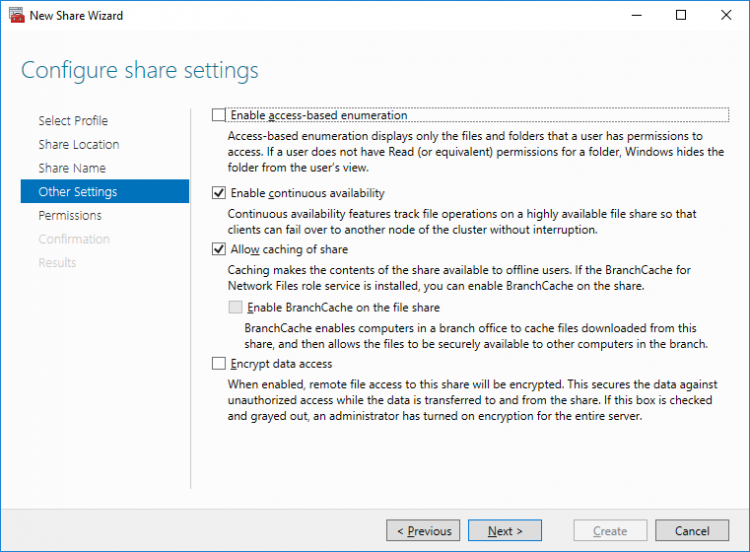
7. Make sure that the Enable Continuous Availability box is checked. Click Next to continue.
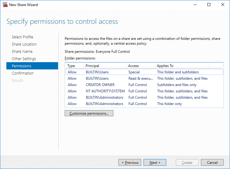
8.Specify the access permissions for the file share.
9. Check whether specified settings are correct. Click Previous to make any changes or Next/Create to continue.

10. Check the summary and click Close.

To manage created SMB File Shares
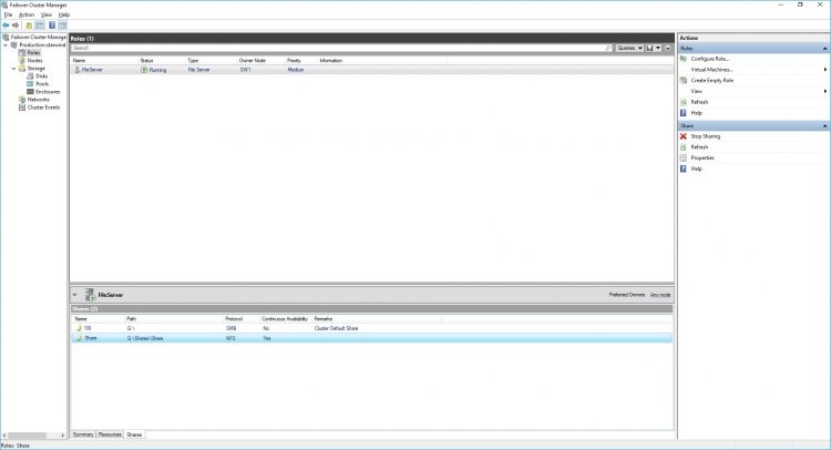
11. Open Failover Cluster Manager.
12. Expand the cluster and click Roles.
13. Choose the File Share role, select the Shares tab, right-click the created file share, and select Properties.
Configuring NFS file share
To Add NFS File Share
1. Open Failover Cluster Manager.
2. Expand the cluster and then click Roles.
3. Right-click the File Server role and then press Add File Share.
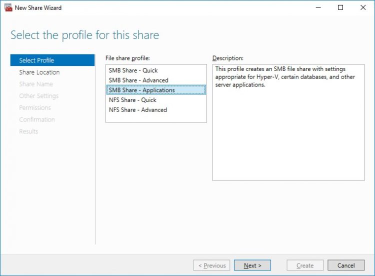
4. On the Select the profile for this share page, click NFS Share – Quick and then click Next.
5. Select available storage to host the share. Click Next to continue.
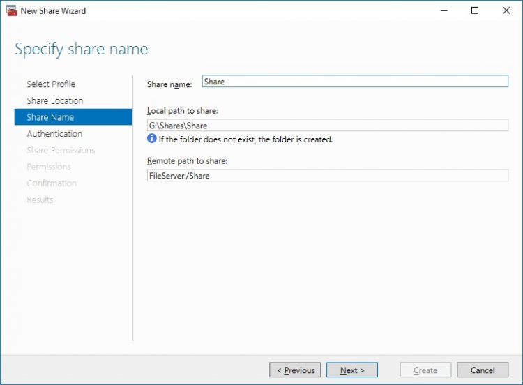
6. Type in the file share name and click Next.
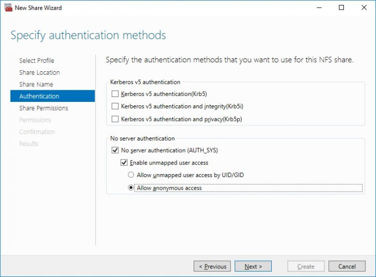
7. Specify the Authentication. Click Next and confirm the message in pop-up window to continue.
8. Click Add and specify Share Permissions.
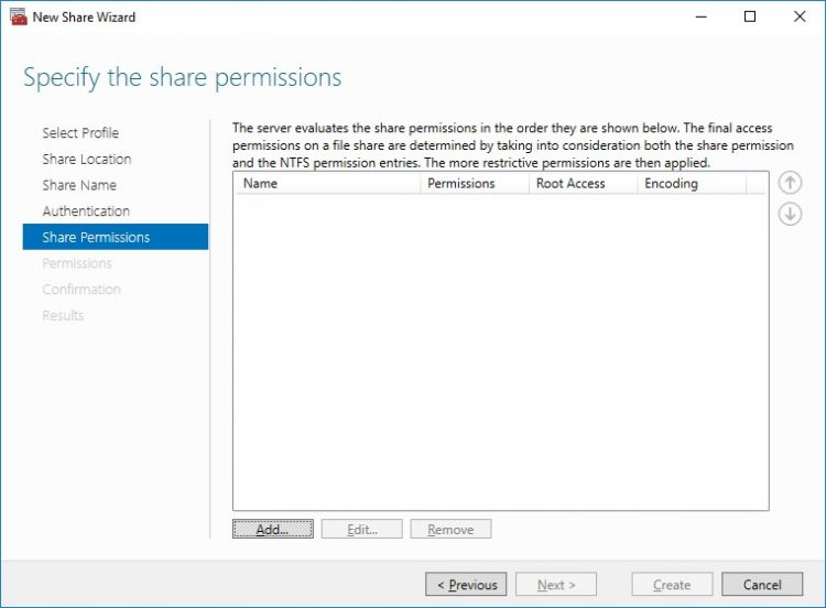
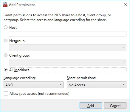
9. Specify the access permissions for the file share.
10. Check whether specified settings are correct. Click Previous to make any changes or click Create to continue.
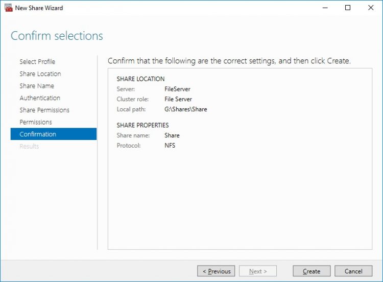
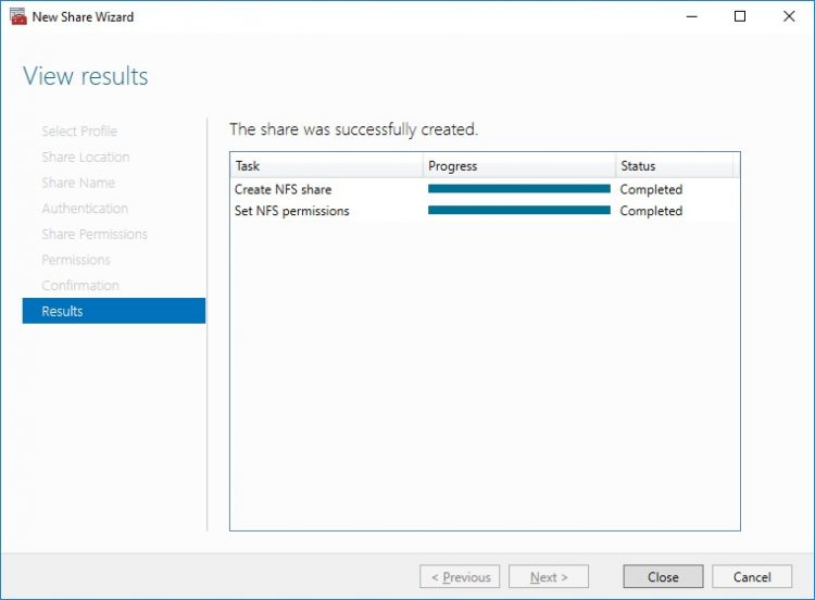
11. Check a summary and click Close to close the Wizard.
To manage created NFS File Shares:
- open Failover Cluster Manager
- expand the cluster and click Roles
- choose the File Share role, select the Shares tab, right-click the created file share, and select Properties
Conclusion
Following this guide, a 2-node Failover Cluster was deployed and configured with StarWind Virtual SAN (VSAN) running in a CVM on each host. As a result, a virtual shared storage “pool” accessible by all cluster nodes was created for storing highly available virtual machines.
