

StarWind Virtual SAN: Feature Configuration Guide for SQL Server 2019 Failover Cluster Instances Deployment on Microsoft Windows Server [Hyper-V]
- October 30, 2018
- 31 min read
INTRODUCTION
This guide is intended for experienced Windows system administrators, IT professionals, and the SQL Server database administrators who would like to install and configure a 2-node Windows Server 2016 Failover Cluster that will host SQL Server Failover Cluster Instance (FCI).
The Windows Server 2016 hosted storage that will be used for building Windows Server Failover Cluster (WSFC) leverages StarWind Virtual SAN for the implementation of a block-level replication.
This document assumes that:
- Windows Server 2016 is installed on each server that would be joined to the cluster and to the Active Directory (AD) domain.
- The disks (LUNs) are exposed to the servers that should be clustered and are configured according to the StarWind Virtual SAN High Availability Best Practices documentation.
- Cluster witness will be located on file share;
A full set of up-to-date technical documentation can always be found here, or by pressing the Help button in StarWind Management Console.
For any technical inquiries please visit our online community, Frequently Asked Questions page, or use the support form to contact our technical support department.
Preconfiguring the Servers
The diagram below illustrates the network and storage configuration of the solution described in this guide.
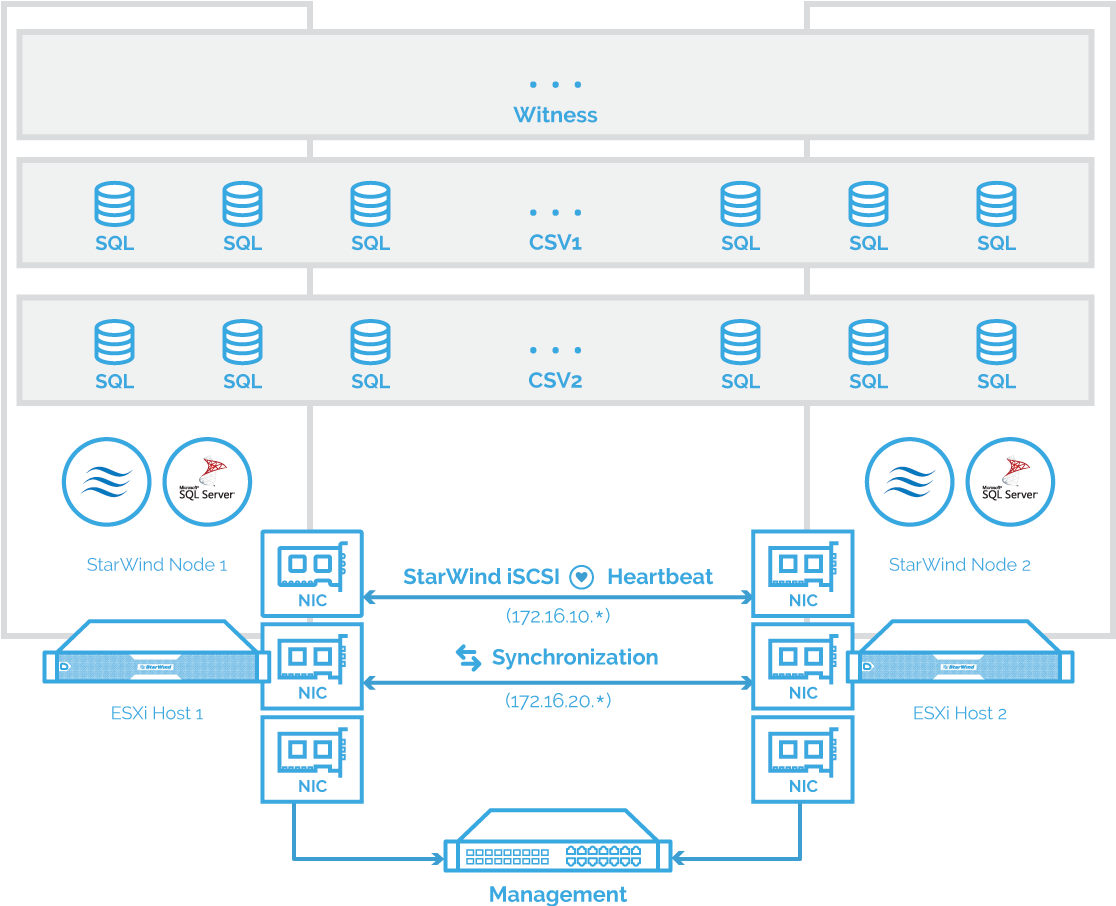
The diagram of a 2-node HA SQL Cluster based on StarWind Virtual SAN
NOTE: Additional network connections may be necessary, depending on the cluster setup and application requirements. For any technical help in regards to configuring additional networks, please, do not hesitate to contact the StarWind Support Department via online community forum, or via support form (depending on the support plan).
1.Make sure to have a domain controller and the servers added to the domain.
2. Install Failover Clustering and Multipath I/O features on both servers.
3. Configure network interfaces on each node to make sure that Synchronization and iSCSI/StarWind Heartbeat interfaces are in different subnets and connected according to the network diagram above. In this document, 10.1.1.x subnet is used for iSCSI/StarWind Heartbeat traffic, while 10.1.2.x subnet is used for the Synchronization traffic.
The procedures mentioned above can be performed by following the instructions below.
SQL Server 2019 Windows System Requirements
Make sure that server used for SQL Server 2019 deployment satisfies the requirements listed below.
Hardware requirements
Memory: 512 MB minimum for Express, 1 GB for Standard, Developer & Enterprise.
File System: NTFS or ReFS. Please note that other file systems, such as FAT32, are not supported.
Disk space: 6 GB minimum.
Processor speed: Clockspeed of 2 GHz or more. 1.4 GHz minimum.
Processor cores: 2 cores (virtual or physical).
Processor type: 64-bit x64-compatible AMD or Intel CPU only.
All the requirements for the components can be found at following the link:
Software Requirements
- A minimum of .NET 4.6.1 is required. The SQL Server 2019 setup will install the necessary files before the actual installation.
- The SQL Server setup support files and the native client should be installed first.
- Client versions of Windows 10 or 8.1 and Windows Server 2016 or Windows Server 2012 R2. Windows Server Essentials and Foundation Editions are also supported.
However, the SQL Server setup requires a GUI and will not work on the Core editions. - To install all the components, 8030 MB of the hard disk space is required.
- The supported storage types are the following:
– Local
– Shared
– Storage Spaces (including S2D)
– SMB (supported with certain limitations)
- SQL Server has limitations when installing on a domain controller (DC). Failover clustering is not supported on a DC.
The SQL Server Core engine is 64-bit only and does not support the 32-bit editions of Windows 8 or Windows 10. Barring a few 32-bit components (such as Client Tools, Data Quality Client), all other parts require the native 64-bit support.
Enabling Multipath Support
4. Open the MPIO Properties manager: Start -> Windows Administrative Tools -> MPIO. Alternatively, run the following PowerShell command:
mpiocpl
5. In the Discover Multi-Paths tab, tick the Add support for iSCSI devices checkbox and click Add.
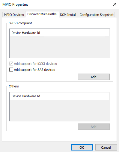
6. When prompted to restart the server, click Yes to proceed.
NOTE: Repeat the same procedure on the other server.
Installing and Configuring StarWind Virtual SAN
7. Download the StarWind setup executable file from StarWind website:
https://www.starwind.com/registration-starwind-virtual-san
NOTE: The setup file is the same for x86 and x64 systems, as well as for all Virtual SAN deployment scenarios.
The process outlined below should be performed on both SQLNODE1 and SQLNODE2 nodes.
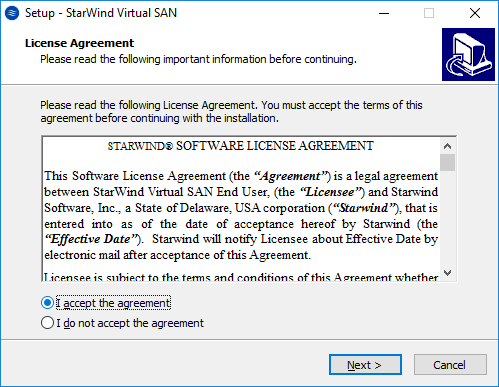
To install StarWind Virtual SAN, run the setup file on SQLNODE1.
8. Read and accept the License Agreement. Click Next to continue.
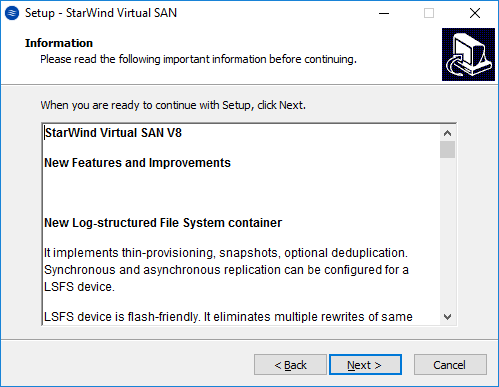
9. Carefully read the information about new features and improvements. Text highlighted in red indicates warnings for users who are updating existing software installations. Click Next to continue.
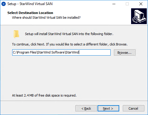
10. Click Browse to modify the installation path if necessary. Click Next to continue.
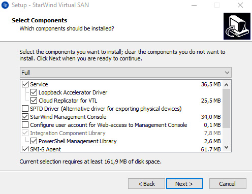
11. In the Select Components dialog box, select Full in the drop-down list and click Next.
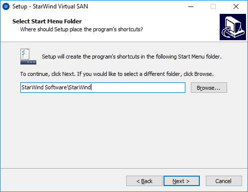
12. Specify the Start Menu Folder. Click Next to continue.
13. Enable the checkbox, if a desktop icon needs to be created. Click Next to continue.

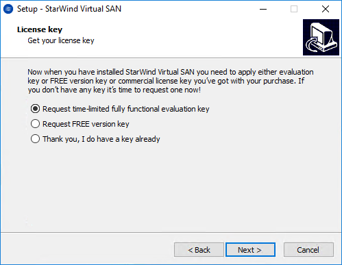
14. In the License key dialog box, provide the appropriate license key. Click Next.
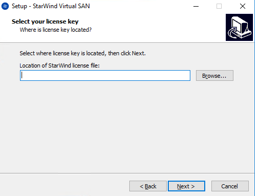
15. Click Browse… to locate the license file. Click Next to continue.
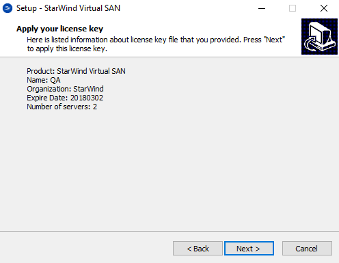
16. Review the licensing information. Click Next to continue.
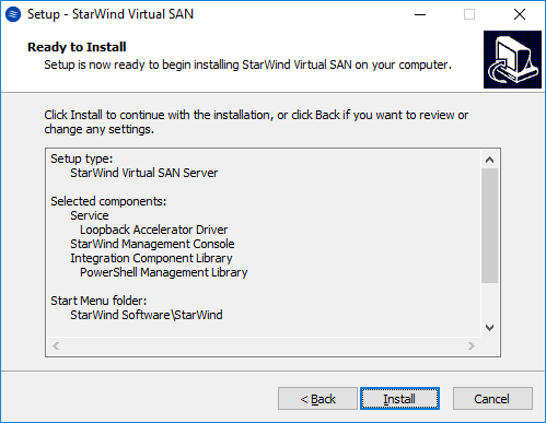
17. Verify the installation settings. Click Back to make any changes or click Install to proceed with the installation.
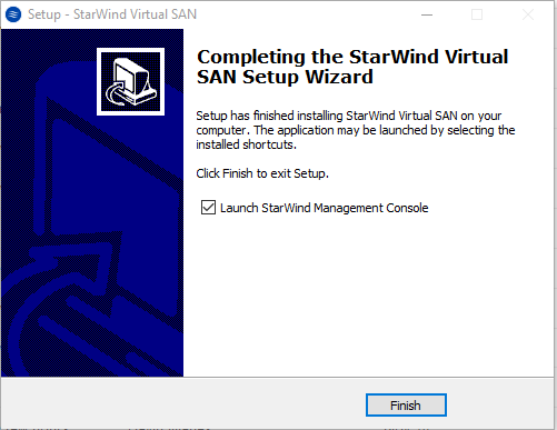
18. Enable the appropriate checkbox to launch StarWind Management Console right after the Setup Wizard is closed. Click Finish to close the Wizard.
19. After completing the installation, repeat all the steps to set up StarWind Virtual SAN on the second node (in this case, SQLNODE2).
Configuring StarWind Virtual SAN
20. After StarWind Virtual SAN has been set up on both SQLNODE1 and SQLNODE2 nodes, the highly-available storage for WSFC should be configured. These steps can be performed on any of the virtual machines with StarWind Virtual SAN installed. In this part, these steps will be performed on SQLNODE1.
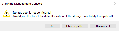
21. StarWind Management Console will ask to specify the default storage pool on the server which it connects to for the first time. Configure the default storage pool to use one of the volumes that have been prepared previously. All devices created through the Add Device Wizard will be stored on it. In case an alternative storage path is required for StarWind virtual disks, use the Add Device (advanced) menu item.
22. Press the Yes button to configure the storage pool. If the storage pool destination needs to be changed, click Choose path… and point the browser to the necessary disk.
NOTE: Any of the arrays which will be used by StarWind Virtual SAN to store virtual disk images should meet the following requirements:
- Be initialized as GPT.
- Have a single NTFS-formatted partition.
- Have a drive letter assigned.
The steps below cover the procedure of an HA device creation for the SQL-DISK-1 drive. Other devices should be created in the same way.
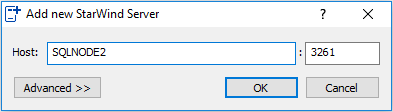
23. In StarWind Management Console, right-click the Servers field and press the Add Server button. Add a new StarWind Server which will be used as the second StarWind VSAN node.
24. Select the StarWind Server where the device needs to be created and press the Add Device (advanced) button on the toolbar.
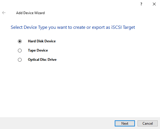
25. Add Device Wizard will appear. Select Hard Disk Device and click Next.
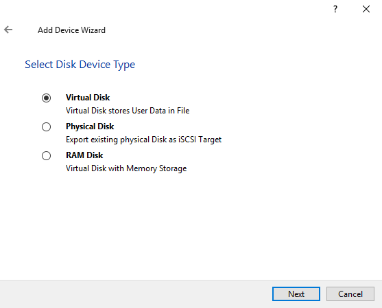
26. Select Virtual Disk as a device type and click Next.
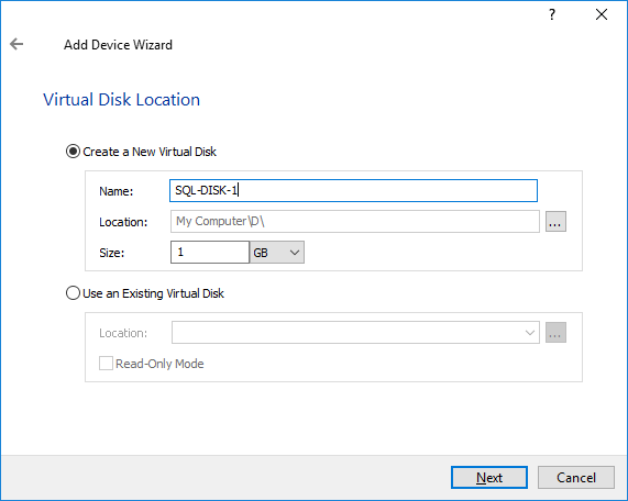
27. Specify the Virtual Disk Location, Name, and Size. Click Next.
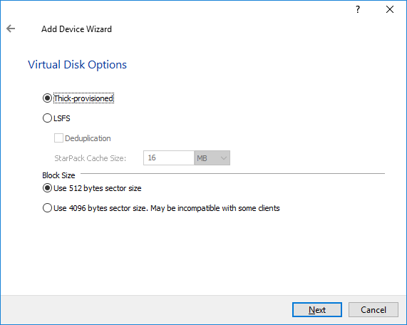
28. Specify Virtual Disk Options and click Next.
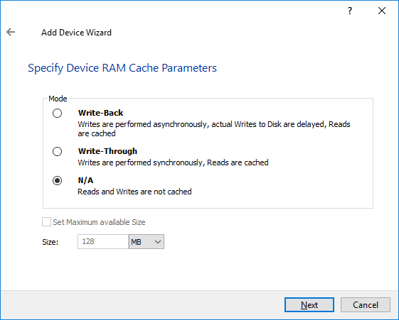
29. Define the caching policy and specify the cache size (in GB). Click Next to continue.
NOTE: The basic recommendation is to use 1 GB of L1 cache per 1 TB of storage capacity. The cache size should correspond to the storage working set of the servers.
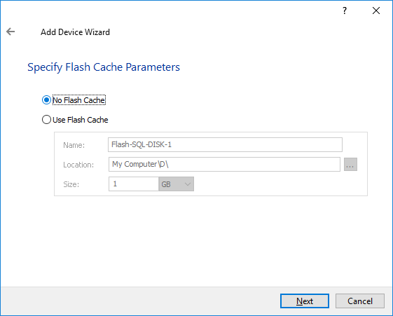
30. Define Flash Cache Parameters if necessary and click Next.
NOTE: The recommended size of the L2 cache is 10% of the initial StarWind device capacity.
31. Specify the Target Parameters. Enable the Target Name checkbox to customize the target name. Otherwise, the name will be generated automatically based on the target alias. Click Next.
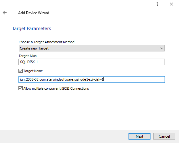
32. Click Create to add a new device and attach it to the target. Then click Close to complete the Wizard.
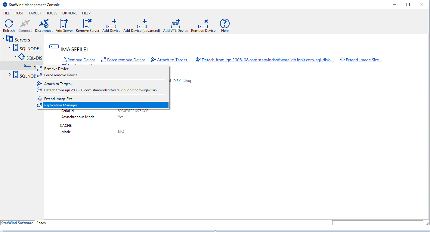
33. Right-click the newly created device and select Replication Manager. In the appeared window, press the Add Replica button.
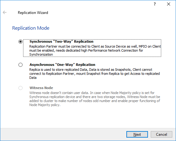
34. Select the Synchronous “Two-Way” Replication mode. Click Next to proceed.
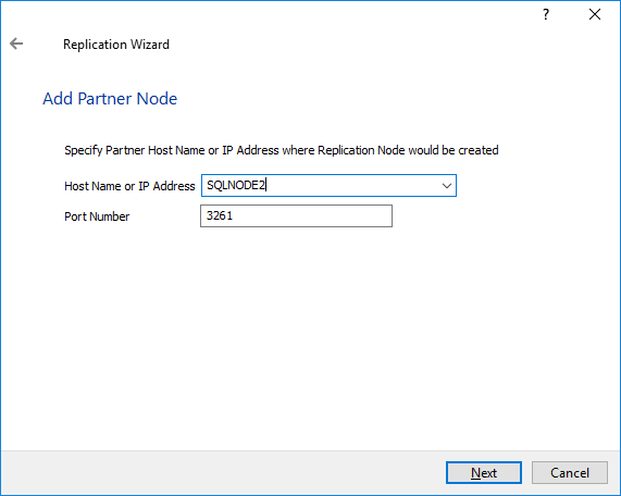
35. Specify the partner server Host Name or IP address. The default StarWind management port is 3261. If a different port has been configured, type it in the Port Number field. Click Next to continue.
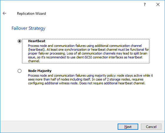
36. Select the Failover Strategy for the HA device. This document assumes configuring the Heartbeat failover strategy. Click Next to continue.
NOTE: With the Heartbeat failover strategy, one node remains active, even in case of all partner nodes failure.
With the Node Majority failover strategy, the system can tolerate failure of only one node. If two nodes fail, the third one will become unavailable to the clients’ requests.
The creation of an HA device with the Node Majority failover strategy is covered in the following document:
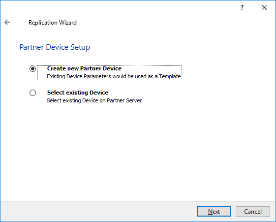
37. Select Create new Partner Device and click Next.
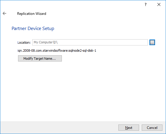
38. Specify the partner device Location if necessary, and/or modify the target name of the device. Click Next.
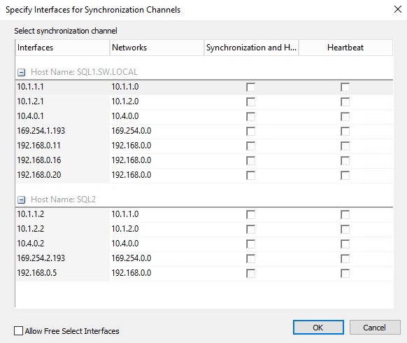
39. Select the Networks for Synchronization and Heartbeat for the HA device by clicking Change Network Settings.
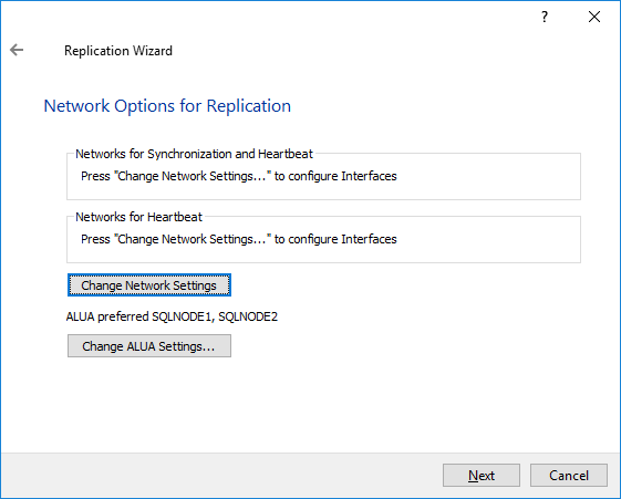
40. Specify the interfaces for Synchronization and Heartbeat. Press OK. Then click Next.
NOTE: It is recommended to configure the Heartbeat and iSCSI networks on the same interfaces to avoid the split-brain issue. If the Synchronization and Heartbeat interfaces are located on the same network adapter, it is recommended to assign one more Heartbeat interface to a separate adapter.
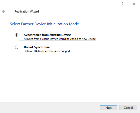
41. Select Synchronize from existing Device as a partner device initialization mode. Click Next.
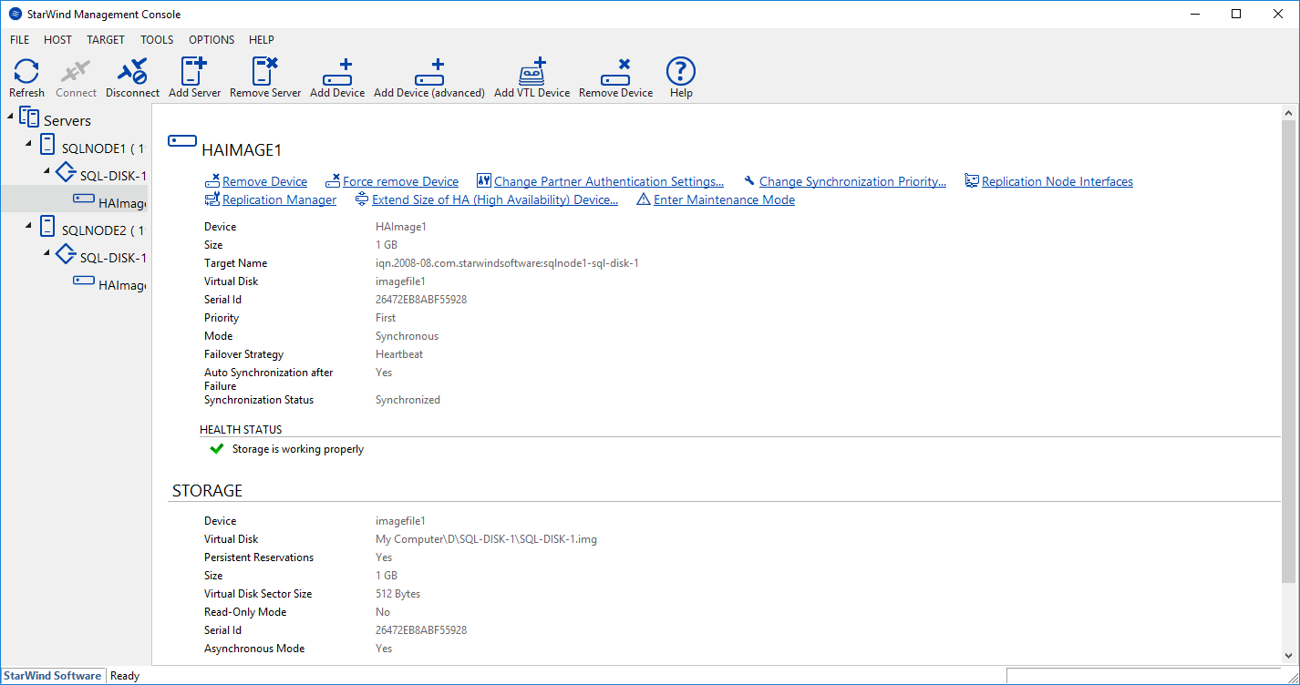
42. Press the Create Replica button and then click Close. The added devices will appear in StarWind Management Console.
Discovering Target Portals
This part describes how to connect the iSCSI storage to the servers that will be added to the cluster.
NOTE: Windows Server 2016 comes with the iSCSI Initiator software that enables connection of a Windows host to an iSCSI storage array using network adapters. In this example, the iSCSI target is the same as the WSFC nodes. To launch the tool from the Server Manager dashboard, in the Tools tab, select iSCSI Initiator.
Also, make sure that Windows Firewall is configured to allow the iSCSI traffic on both SQLNODE1 and SQLNODE2 nodes.
The steps below are performed initially on SQLNODE1.

43. The message informing that the Microsoft iSCSI service is not running appears. Ignore it and click Yes to continue.
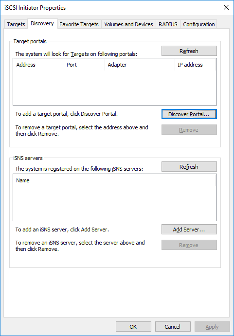
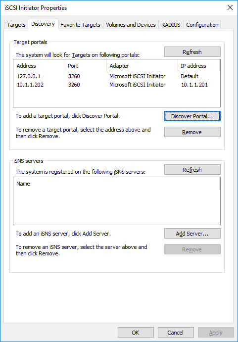
44. In the iSCSI Initiator Properties window, select the Discovery tab.
45. Click the Discover Portal… button. The Discover Target Portal dialog box appears.
46. Type in the first IP address of the partner node that will be used to connect to highly-available iSCSI devices. For this example, a loopback IP address of SQLNODE1 is 127.0.0.1.
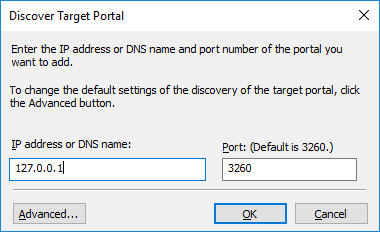
47. Click the Advanced button. Select Microsoft iSCSI Initiator as a Local adapter and select Initiator IP (leave default for 127.0.0.1). Confirm the actions to complete the Target Portal discovery.
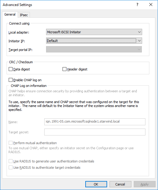
Click OK. Then click OK again to close the Discover Target Portal dialog box.
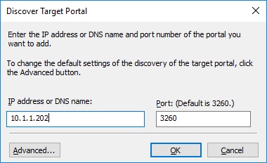
48. Click the Discover Portal button once again. The Discover Target Portal dialog appears.
49. Type in the IP address of the partner node that will be used to connect to the HA iSCSI devices. For this example, the IP address of SQLNODE2 is 10.1.1.202. Click the Advanced… button.
50. Select Microsoft iSCSI Initiator as the Local adapter. Select the Initiator IP in the same subnet as the IP address of the partner server from the previous step. Click OK to confirm the actions and complete the Target Portal discovery.
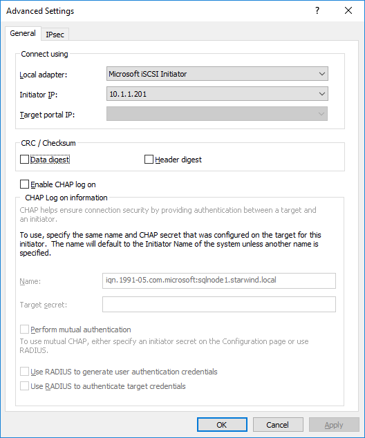
Then click OK again to close the Discover Target Portal dialog box.
SQLNODE1 should be connected to both iSCSI Targets via the following target portals.
51. Repeat the same steps for the second node SQLNODE2 to add all target portals.
NOTE: SQLNODE2 should be also connected to both iSCSI Targets via the following target portals.

Connecting Targets and Configuring Multipathing
This part describes how to connect the servers to the iSCSI targets and configure multipathing.
NOTE: The steps below are performed initially on SQLNODE1.
52. In the iSCSI Initiator Properties window, open the Targets tab. The iSCSI targets configured should be listed in the Discovered targets section.
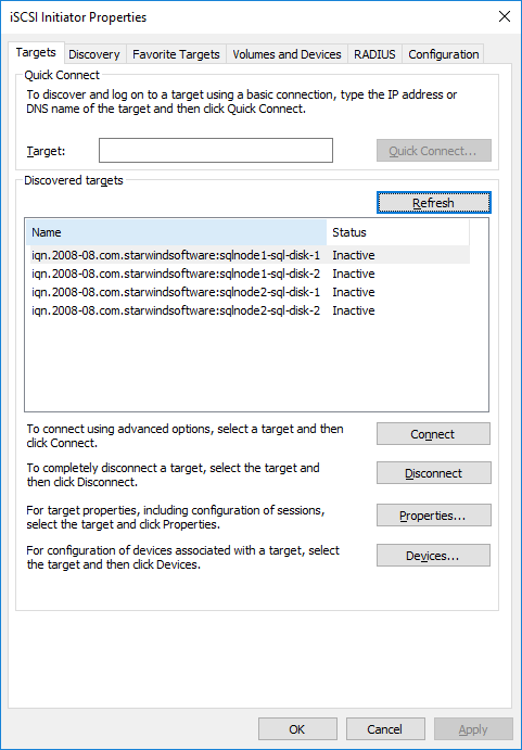
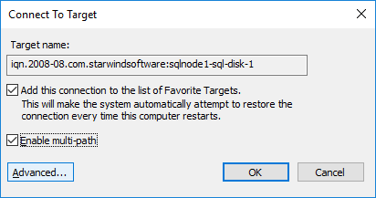
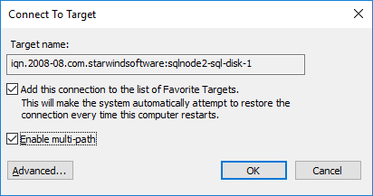
53. Select the first target in the list and then click Connect.
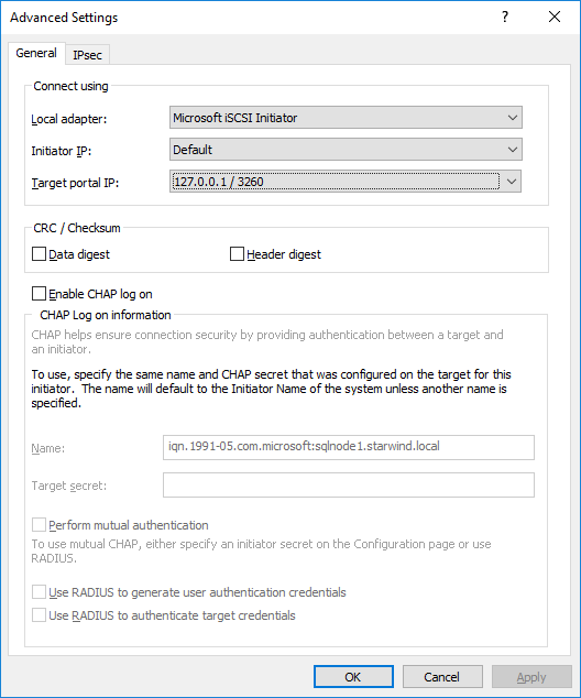
54. Enable both checkboxes and click Advanced…
55. Select Microsoft iSCSI Initiator in the Local adapter drop-down menu. In Target portal IP, select 127.0.0.1. Confirm the actions.
56. Select the partner target from another StarWind node (SQLNODE2) and click Connect. In this case, 10.1.1.x subnet is used to connect the target.
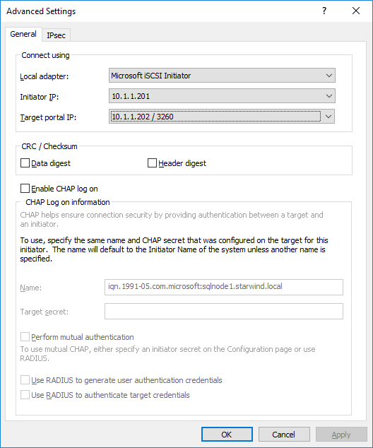
57. Enable both checkboxes and click Advanced…
58. Select Microsoft iSCSI Initiator in the Local adapter drop-down menu. In the Initiator IP field, select the IP address for the iSCSI channel. In the Target portal IP, select the corresponding portal IP from the same subnet. Confirm the actions.
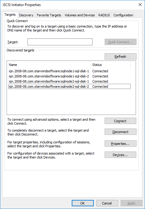
59. Repeat the steps above for all HA device targets remaining. The result should look like in the screenshot below.
60. Repeat the steps described in this part on SQLNODE2.
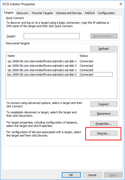
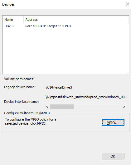
61. Configure the MPIO policy for each target with the Failover Only. Select the target located on the local server and click Devices.
62. In the Devices… dialog, click MPIO…
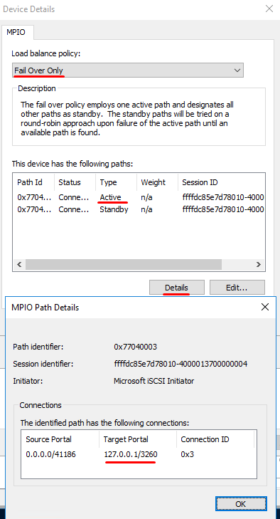
63. Select the appropriate load balancing policy.
NOTE: In case the Failover Only MPIO policy is used, make sure to check that the local path (127.0.0.1) is set to Active, while the partner connection is set to Standby.
Initialize and Format the Disks
This part describes how to initialize and format the iSCSI disks. To launch the tool from the Server Manager dashboard, select Computer Management in the Tools tab.
64. Open the Disk Management tool.
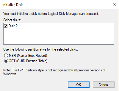
65. When the Initialize Disk dialog box appears, make sure that all iSCSI disks previously configured are selected. Click OK to initialize the disks as GPT.
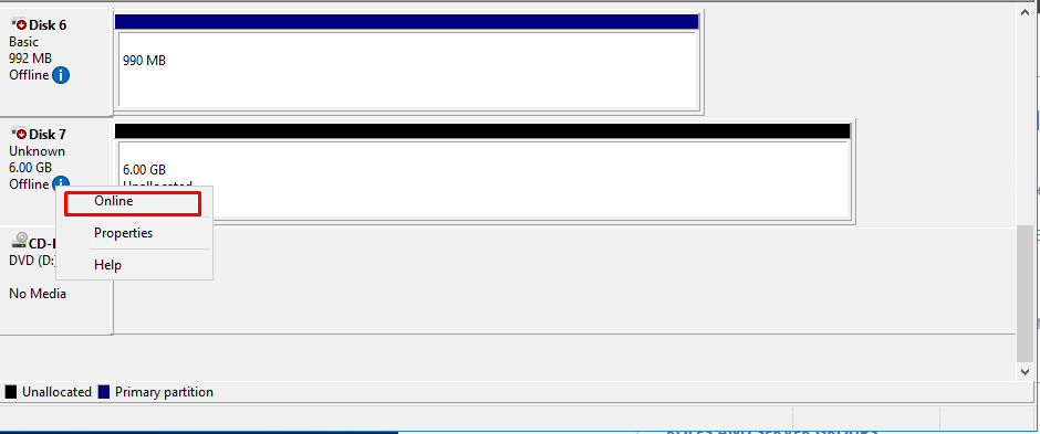
66. Right-click any of the disks that need to be configured. Select Online.
67. To create a disk partition, right-click the unallocated space and select New Simple Volume.
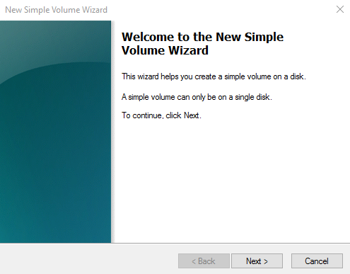
68. In the Welcome to the New Simple Volume Wizard dialog box, click Next.
69. In the Specify Volume Size dialog box, enter the volume size and click Next.
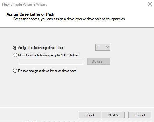
70. In the Assign Drive Letter or Path dialog box, specify the drive letter to be used and click Next.
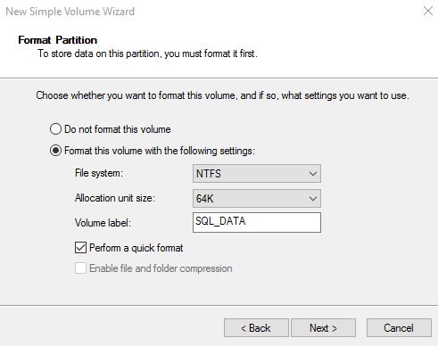
71. In the Format Partition dialog box:
- Make sure that the NTFS file system is selected.
- According to Microsoft Best Practices on allocation unit size, the unit size should be 64K.
- In the Volume label text box, enter the appropriate name. For this example, SQL_DATA is used. This volume label will be used to verify the configuration on the other cluster node.
Click Next.
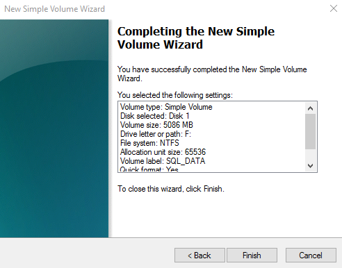
72. In the Completing the New Simple Volume Wizard dialog box, review the settings configuration and click Finish.
73. Repeat the steps above on all iSCSI disks that will be configured as part of the cluster.
74. Repeat steps described in this part on SQLNODE2. There is no need to initialize the iSCSI disks.
Running Failover Cluster Validation Wizard
This part describes how to run Failover Cluster Validation Wizard from the Failover Cluster Management console. To launch the tool from the Server Manager dashboard, select Failover Cluster Manager in the Tools tab.
NOTE: These steps can be performed on any of the servers that will act as the WSFC nodes. The steps below are performed on SQLNODE1.
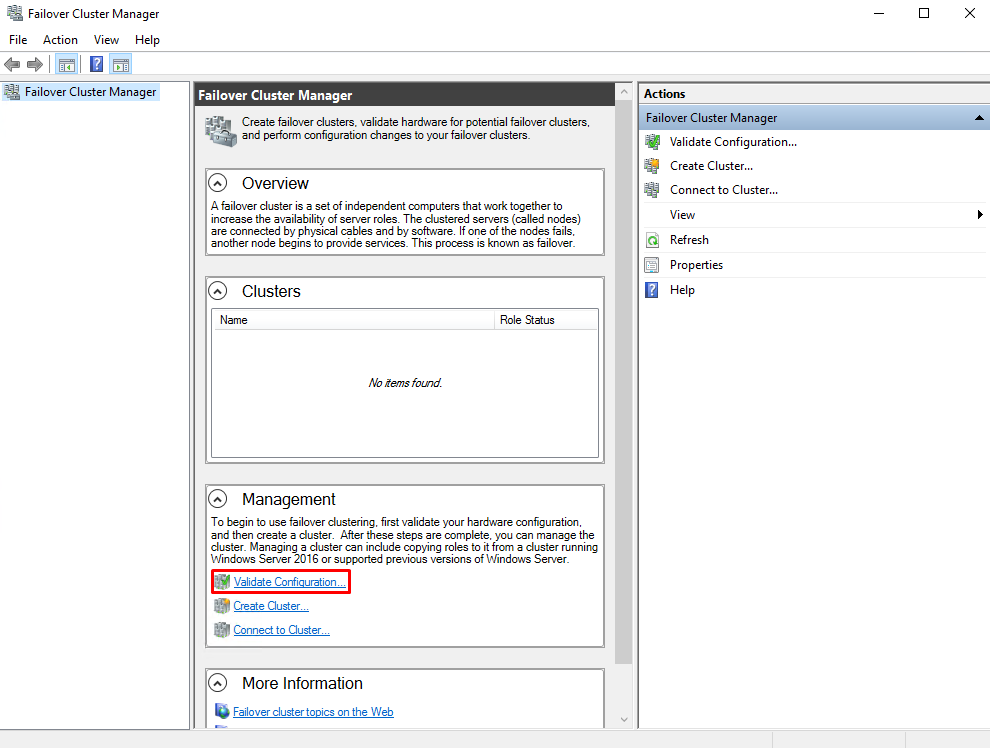
75. In the Failover Cluster Manager console, in the Management section, click on the Validate Configuration… link to run Validate a Configuration Wizard.
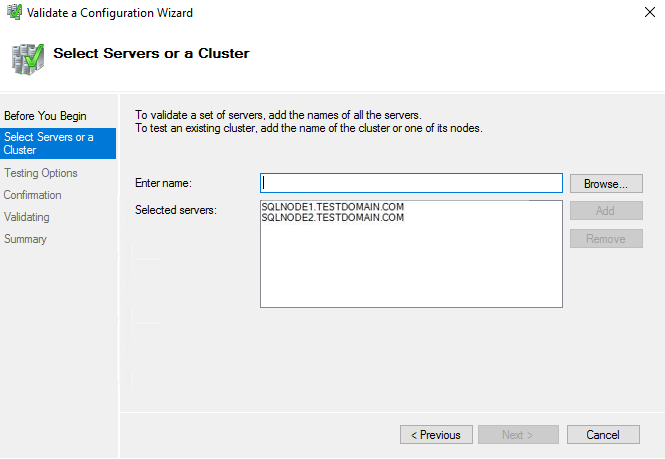
76. In the Select Servers or a Cluster dialog box, enter the host names of the nodes that will be added as members of the cluster. Click Next.
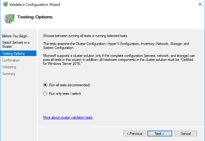
77. In the Testing Options dialog box, click Next to run all the necessary tests to validate whether the nodes are ready for clustering.
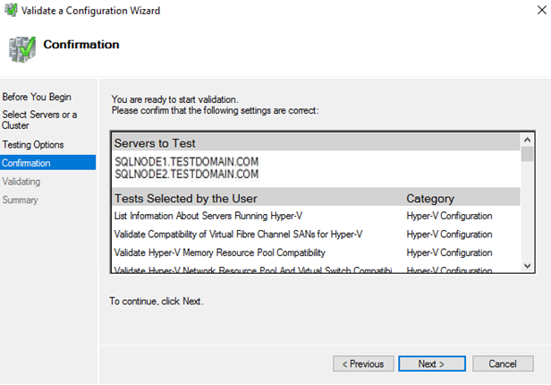
78. In the Confirmation dialog box, click Next to run all the necessary validation tests.
79. In the Summary dialog box, verify that the report returns successful results. Click Finish to create WSFC.
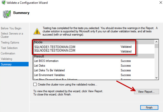
NOTE: Validate a Configuration Wizard may report warning messages pertaining to the storage. Resolve all errors prior to proceeding with the next steps and ignore the storage warnings since in this case, the replicated storage is used instead of shared disks.
Creating Windows Server 2016 Failover Cluster
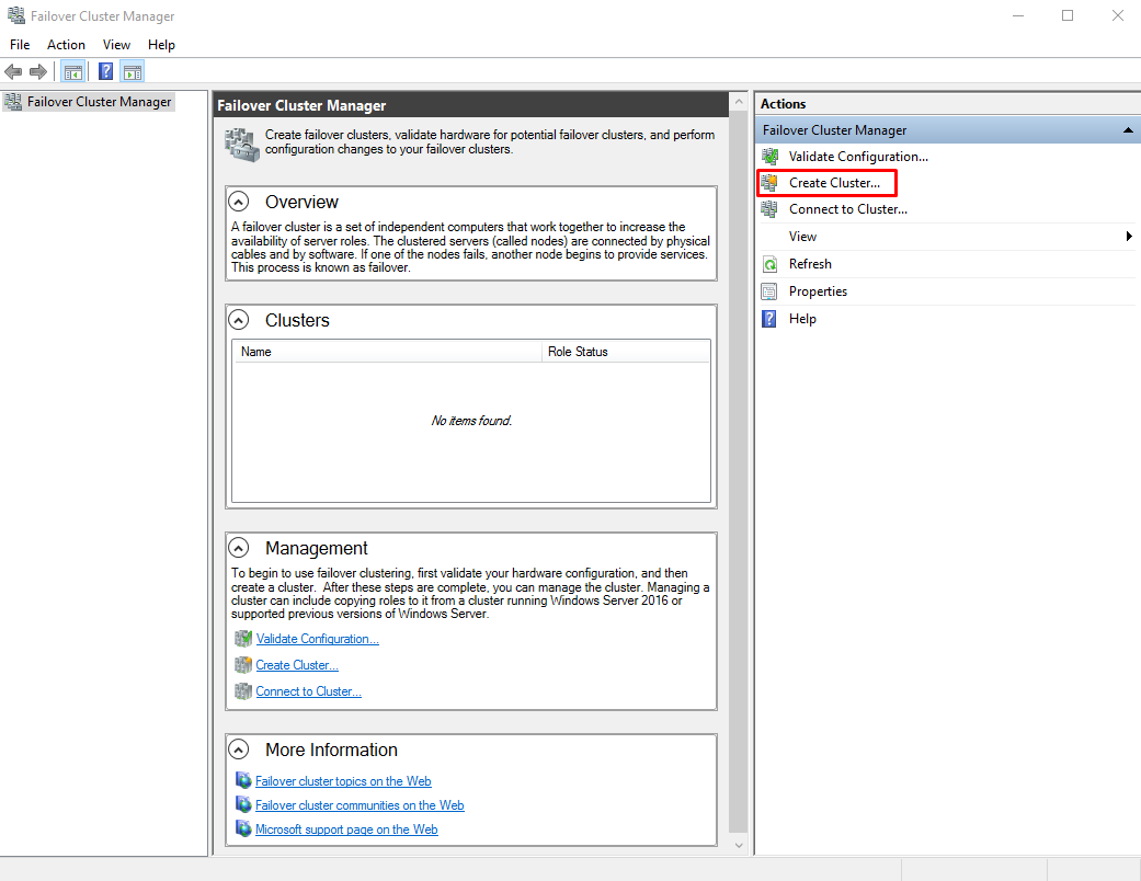
This part describes how to create Windows Server 2016 Failover Cluster from the Failover Cluster Manager console. To launch the tool from the Server Manager dashboard, select Failover Cluster Manager in the Tools tab. Alternatively, the Create Cluster Wizard will automatically run after the Failover Cluster Validation Wizard is completed.
NOTE: These steps can be performed on any servers that will act as the WSFC nodes. The steps below are performed on SQLNODE1.
80. In the Management section, click on the Create Cluster… link to run the Create Cluster Wizard.
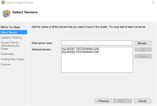
81. In the Select Servers dialog box, enter the host names of the nodes that will be added as members of the cluster. Click Next.
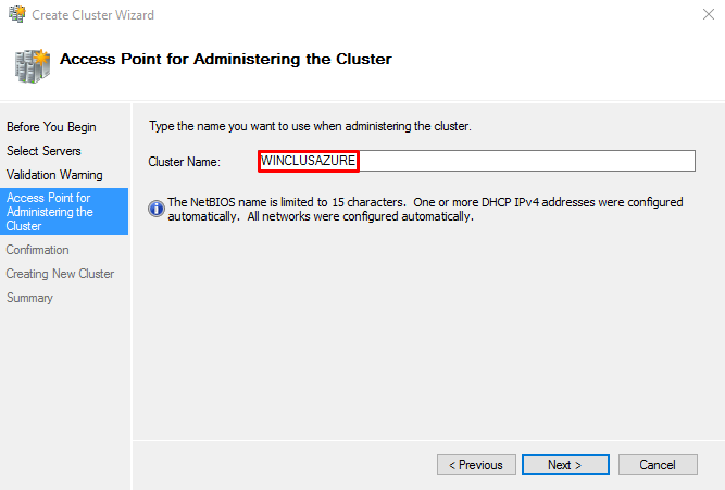
82. In the Access Point for Administering the Cluster dialog box, enter the WSFC virtual host name/client access point that will be used to administer the cluster. WSFC will use a DHCP-assigned IP address for the virtual host name since both SQLNODE1 and SQLNODE2 use DHCP-requested IP addresses, not statically assigned. Click Next.
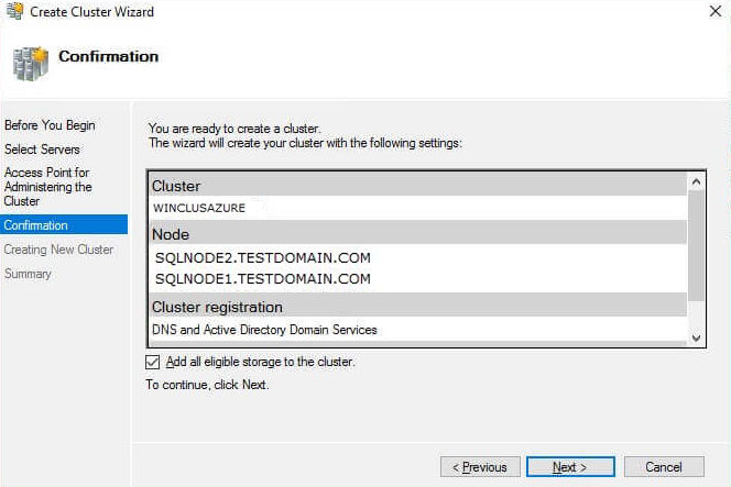
83. In the Confirmation dialog box, click Next. This will configure Failover Clustering on both nodes of the cluster, add the configured replicated storage, add Active Directory and DNS entries for the WSFC virtual host name/client access point.
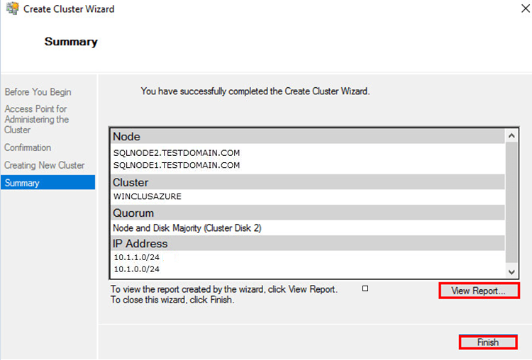
84. In the Summary dialog box, verify that all the settings were specified correctly. According to Microsoft Best Practices, rename all the cluster shared volumes and networks for ease of identification during the installation of SQL Server Failover Cluster Instance.
Configuring Cluster Quorum Settings
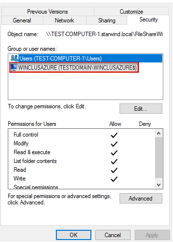
This part describes how to configure the cluster quorum using a file share witness since for WSFC it is needed to add another vote to the cluster for maintaining the quorum. The file share must be created on the domain controller for this purpose and granted the Windows Failover Cluster virtual server name Read/Write permissions.
NOTE: These steps can be performed on any of the servers that will act as the WSFC nodes. The steps below are performed on SQLNODE1.
85. Open the Failover Cluster Manager console in the Administrator mode.
86. Select the name of the WSFC virtual host name/client access point.
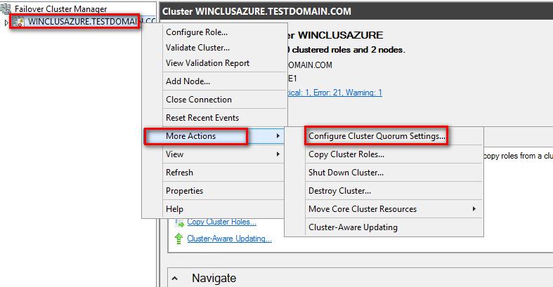
87. Right-click the cluster name and select More Actions. Then click Configure Cluster Quorum Settings… to open Configure Cluster Quorum Wizard.
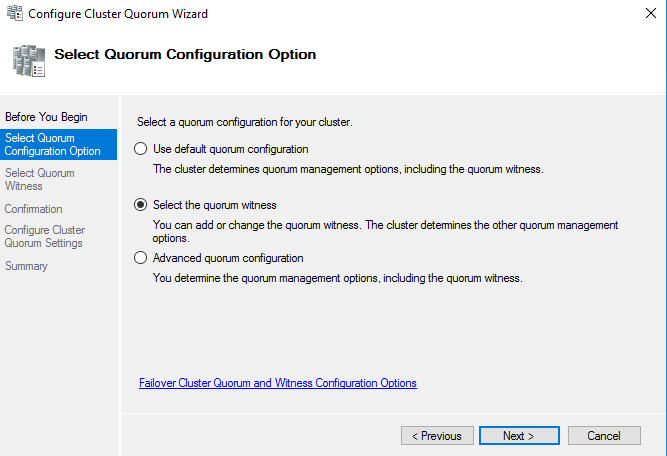
88. In the Select Quorum Configuration Option dialog box, tick the Select the quorum witness option. Click Next.
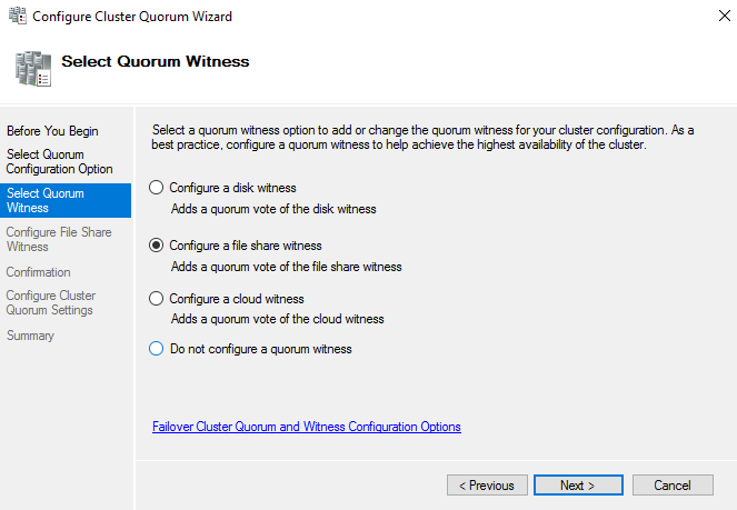
89. In the Select Quorum Witness dialog box, choose the Configure a file share witness option. Click Next.
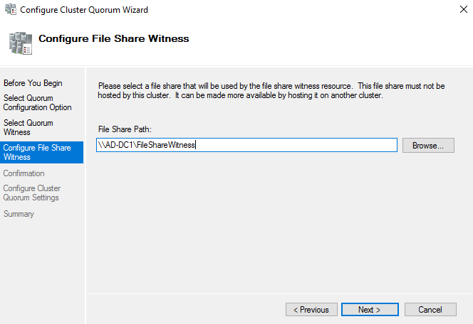
90. In the Configure File Share Witness dialog box, type the File Share Path. Click Next.
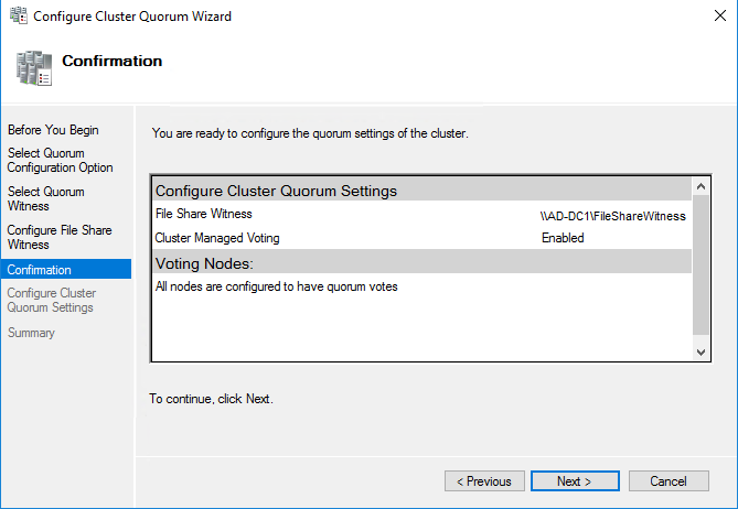
91. In the Confirmation dialog box, review the configuration settings and click Next.
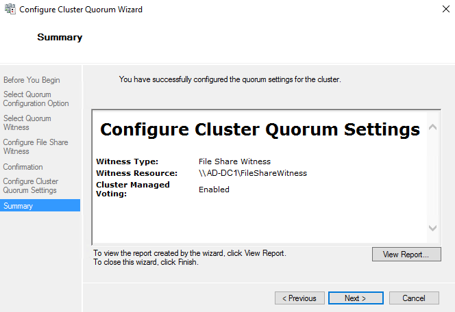
92. In the Summary dialog box, verify that the entire configuration is successful.
Installing SQL Server 2019 Failover Cluster Instance
This part describes how to install a default SQL Server 2019 Failover Cluster instance on Windows Server 2016. The installation process will be performed on the first node of the cluster, SQLNODE1.
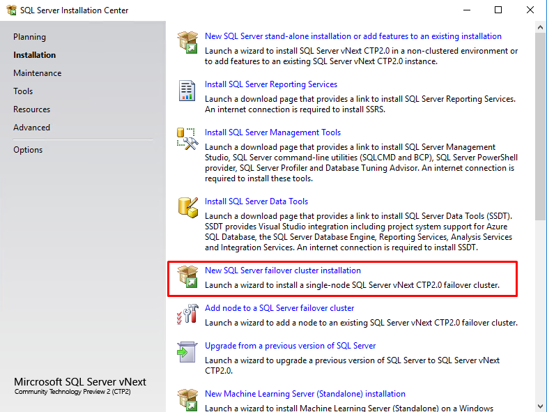
93. Run setup.exe from the SQL Server 2019 installation media to launch the SQL Server Installation Center. Click on the Installation link on the left side.
94. Click on the New SQL Server failover cluster installation link to run the SQL Server 2019 Setup Wizard.
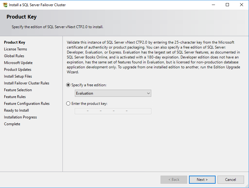
95. In the Product Key dialog box, enter the product key that came with the installation media and click Next.
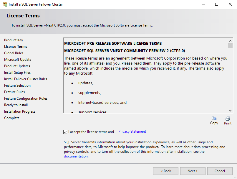
96. In the License Terms dialog box, enable the I accept the license terms and Privacy Statement and click Next.
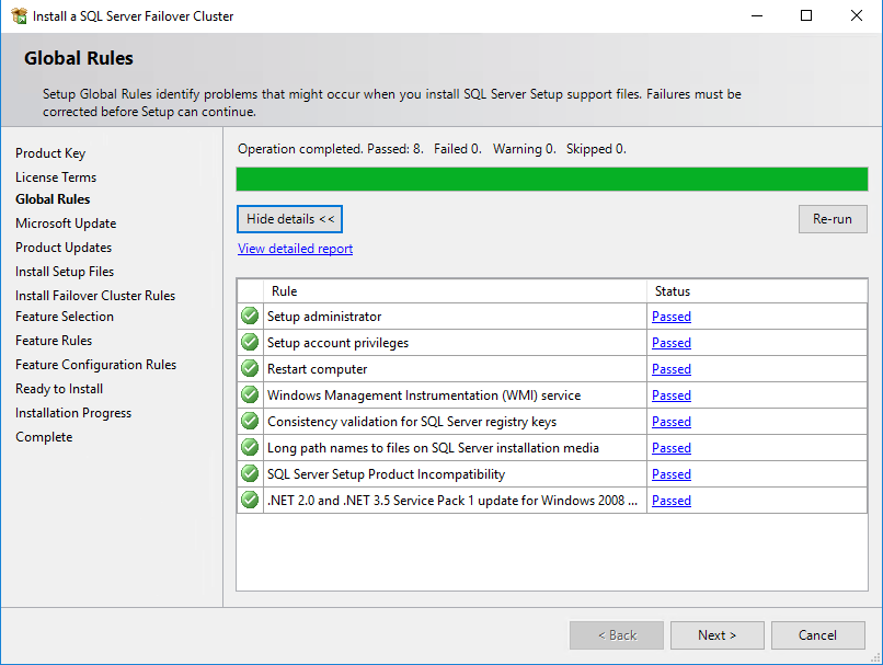
97. In the Global Rules dialog box, validate that the tests return successful results and click Next.
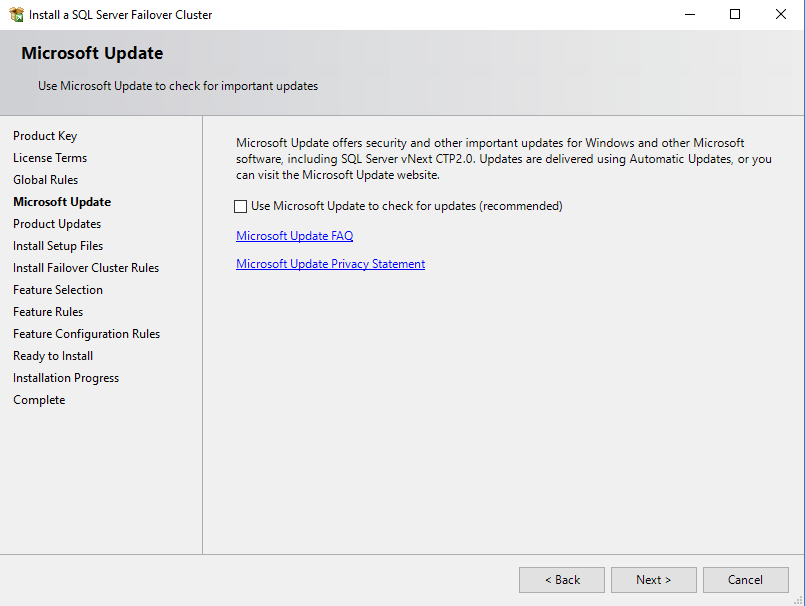
98. In the Microsoft Update dialog box, click Next.
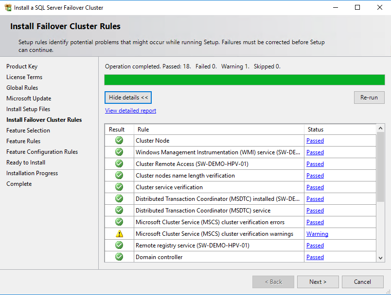
99. In the Install Failover Cluster Rules dialog box, validate that the tests return successful results. If the tests return warnings, make sure they are fixed before proceeding with the installation. Click Next.
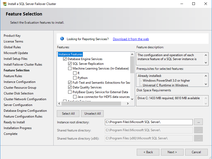
100. In the Feature Selection dialog box, select the Database Engine Services and the Management Tools. Click Next.
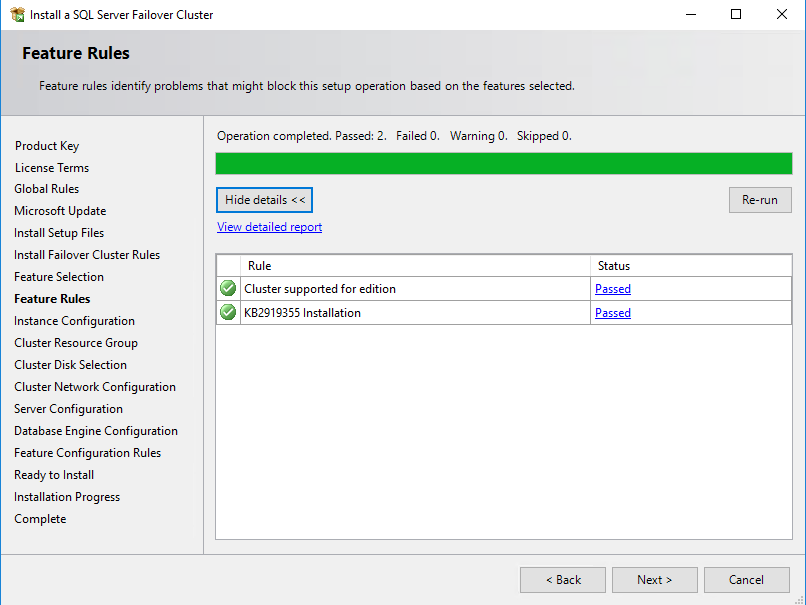
101. In the Feature Rules dialog box, verify that all the rules have passed the tests. If the rules return warnings, make sure they are fixed before proceeding with the installation. Click Next.
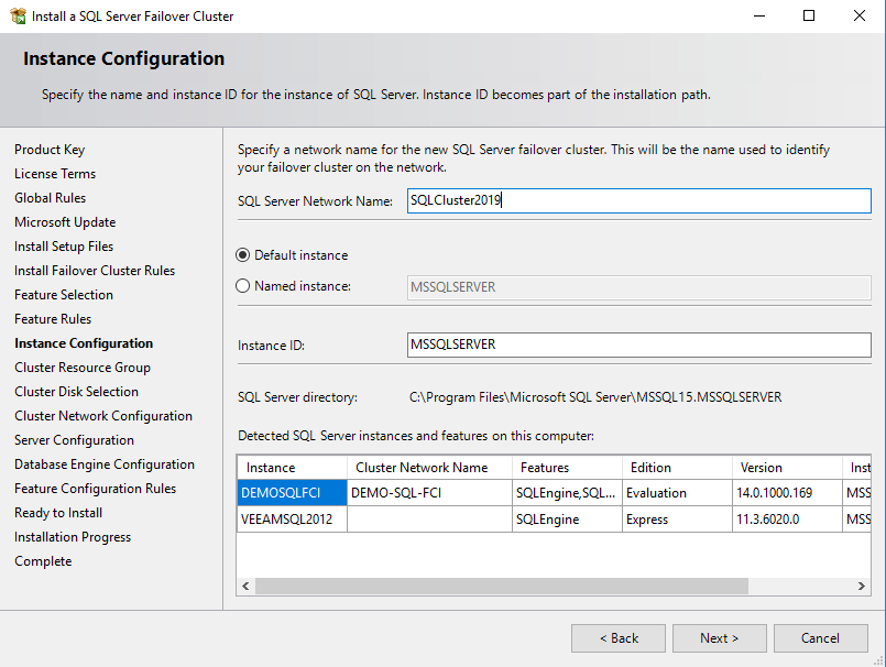
102. In the Instance Configuration dialog box, add the following details:
SQL Server Network Name: type the name of the cluster
Instance ID: MSSQLSERVER
Click Next.
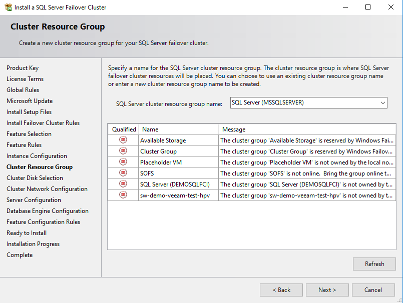
103. In the Cluster Resource Group dialog box, check the resource availability on Windows Server Failover Cluster. It shows that a new Resource Group will be created on the cluster for the SQL Server instance. To specify the SQL Server cluster resource group name, use the drop-down box to clarify an existing group to use or type the name of a new group to create it. Accept all the defaults and click Next.
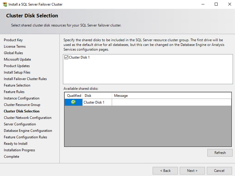
In the Cluster Disk Selection dialog box, select the available disk groups that are to use on the cluster for SQL Server 2019. Click Next.
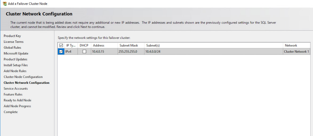
104. In the Cluster Network Configuration dialog box, enter the virtual IP address that the SQL Server 2019 Failover Cluster Instance will use. The checkbox next to the IPv4 column will be used as a static IP address instead of DHCP-assigned. Click Next.
105. Type the IP address: 10.4.0.15 (similar to the virtual IP address for the virtual host name/client access point, the IP address could be any within the range of the Production subnet as long as it is available).
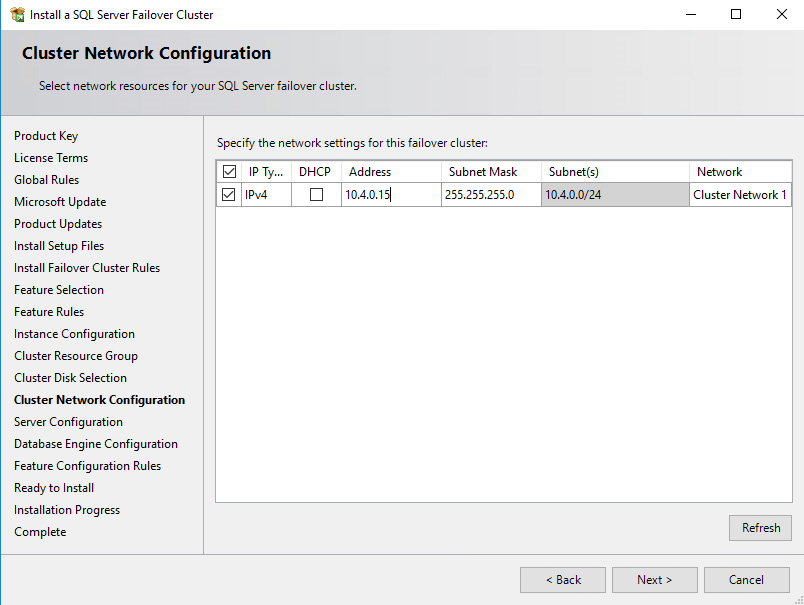
NOTE: The network adapter settings that will be displayed in this dialog box will depend on how the cluster network adapters are configured. Make sure to configure the Heartbeat-iSCSI network adapters with the Do not allow cluster network communication on this network option.
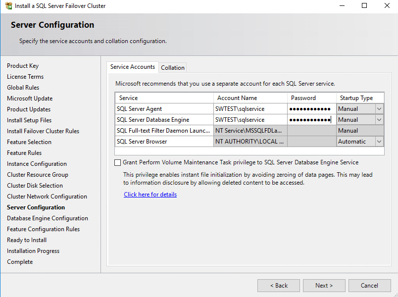
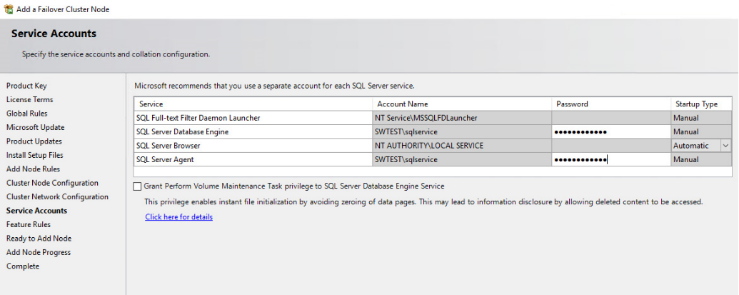
106. In the Server Configuration dialog box, use the following credentials for the SQL Server service accounts in the Service Accounts tab:
SQL Server Agent: SWTEST\sqlservice
SQL Server Database Engine: SWTEST\sqlservice
Make sure that both SQL Server Agent and SQL Server Database Engine services have the Manual Startup Type. Windows Server Failover Cluster will take care of stopping and starting the service. Also, set the Collation property for the instance according to the application requirement. Click Next.
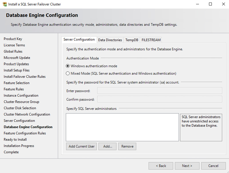
107. In the Database Engine Configuration dialog box, select the appropriate Authentication Mode in the Server Configuration tab. To add the currently logged-on user to the SQL Server administrators group, click the Add Current User button. Otherwise, add the appropriate domain accounts or security groups.
108. In the Data Directories tab, enter the following data based on the Cluster disks available:
Data root directory: J:\
User database directory: J:\MSSQL12.MSSQLSERVER\MSSQL\Data
User database log directory: L:\MSSQL12.MSSQLSERVER\MSSQL\Data
Backup directory: J:\MSSQL12.MSSQLSERVER\MSSQL\Backup
NOTE: SQL Server 2012 has an option to store the tempdb database on a local drive instead of the cluster drive. For WSFC in Microsoft Windows Server 2016, it is recommended to store the tempdb database on a local drive instead of the replicated storage. Make sure that all the nodes in the cluster contain the same directory structure and that the SQL Server service account has Read/Write permissions for those folders.
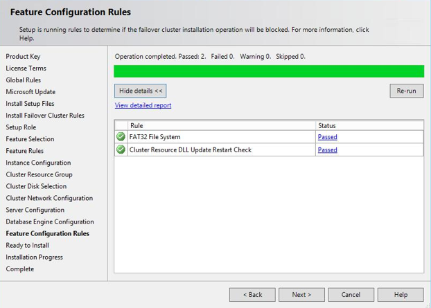
109. In the Feature Configuration Rules dialog box, click Next.
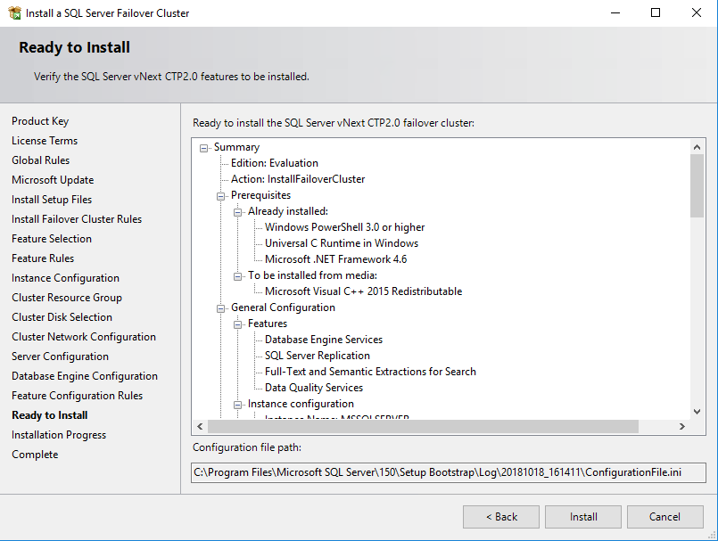
110. In the Ready to Install dialog box, verify that all configurations are correct. Click Next.
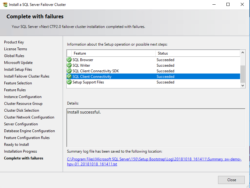
111. Once the installation is finished, in the Complete with failures dialog box, click Close.
Adding Node to SQL Server 2019 Failover Cluster
This part describes how to add a node to SQL Server 2019 Failover Cluster. The installation process will be performed on the second node of the cluster, SQLNODE2.
To add a node to SQL Server 2019 Failover Cluster Instance:
112. Run setup.exe from the installation media to launch the SQL Server Installation Center.
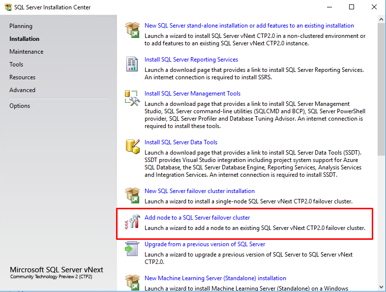
113. Click on the Installation link on the left side and click the Add node to a SQL Server failover cluster link to run the SQL Server 2019 Setup Wizard.
114. In the Product Key dialog box, enter the product key that came with the installation media and click Next.
115. Read and accept the License Terms dialog box and click Next.
116. In the Global Rules dialog box, validate that the tests return successful results and click Next.
117. In the Microsoft Update dialog box, click Next.
118. In the Add Node Rules dialog box, validate that the tests return successful results. If the tests return warnings, make sure to fix them before proceeding with the installation. Click Next.
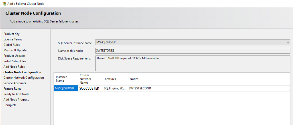
119. In the Cluster Node Configuration dialog box, validate that the information for the existing SQL Server 2019 Failover Cluster Instance is correct. Click the Next button.
120. In the Cluster Network Configuration dialog box, review the configuration of SQL Server Failover Cluster Instance. Click the Next button.
121. In the Service Accounts dialog box, verify that the information of the configuration is the same as what was used to configure the first node. Provide the appropriate password for the SQL Server service accounts. Click the Next button.
122. In the Feature Rules dialog box, click the Next button.
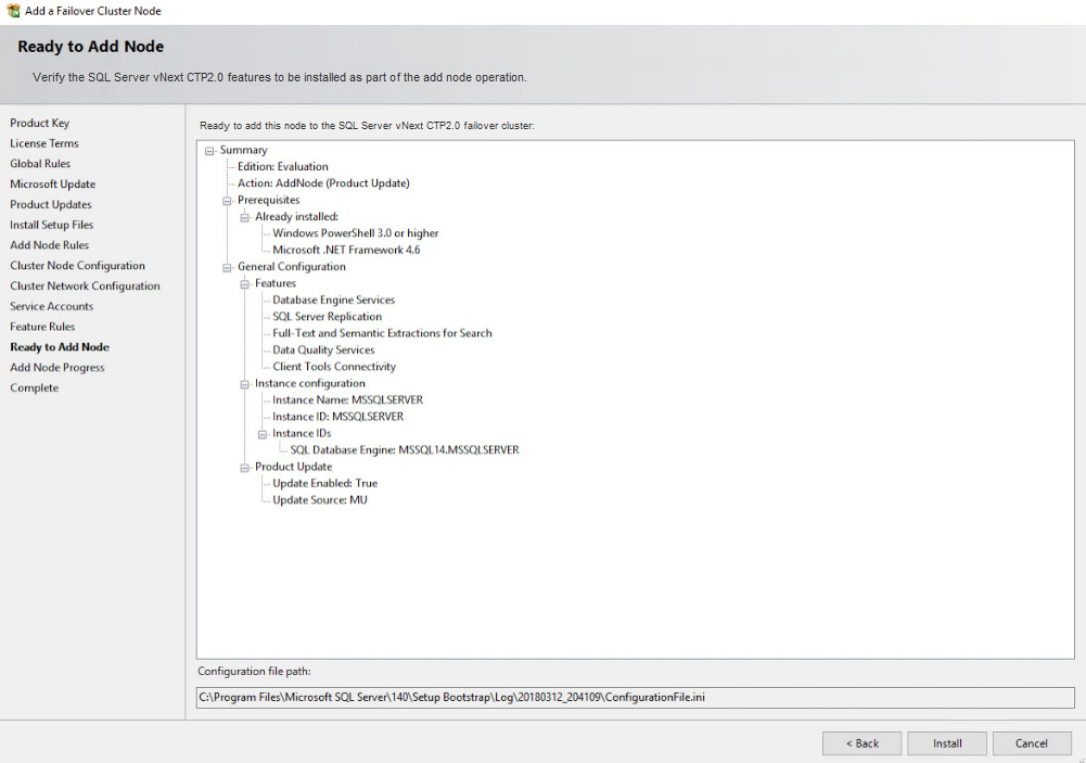
123. In the Ready to Add Node dialog box, verify that all settings are correct and click Install.
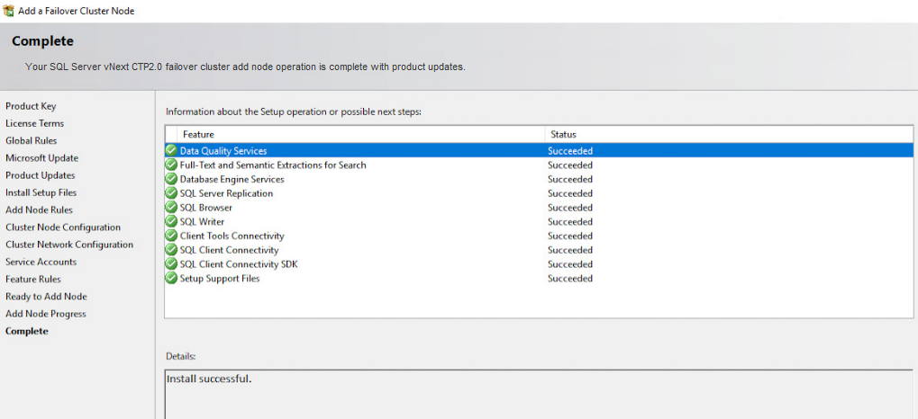
124. Once the installation is completed, click the Close button in the Complete dialog box. This concludes by adding a node to SQL Server 2019 Failover Cluster.
NOTE: When storing the tempdb database on a local drive instead of a replicated drive, make sure that:
- The same drive letter and folder structure exist on all nodes in the cluster.
- The SQL Server service account has appropriate permissions for the folder where tempdb will be created.
CONCLUSION
The steps described in this guide allow successfully configuring a 2-node Windows Server 2016 Failover Cluster that will host SQL Server 2019 Failover Cluster Instance (FCI). StarWind Virtual SAN was taken as the basis for the use in the Windows Server 2016 hosted storage during the implementation of a block-level replication and creating Windows Server Failover Cluster. StarWind VSAN ensures data safety of the entire system and maintains continuous application availability.
