

StarWind Virtual SAN® Hyperconverged 2-Node Scenario with Hyper-V Server 2016
- August 14, 2018
- 25 min read
INTRODUCTION
StarWind Virtual SAN® is a native Windows hypervisor-centric hardware-less VM storage solution. It creates a fully fault-tolerant and high-performing storage pool built for the virtualization workloads by mirroring existing server storage and RAM between the participating storage cluster nodes. The mirrored storage resource is then connected to all the cluster nodes and treated as a local storage by all hypervisors and clustered applications. High availability is achieved by providing the multipath access to all storage nodes. StarWind Virtual SAN delivers supreme performance compared to any dedicated SAN solution since it runs locally on the hypervisor and all I/O are processed by local RAM, SSD cache, and disks. This way it never gets bottlenecked by storage fabric.
This guide is intended for experienced Windows Server users or system administrators. It provides the detailed instructions on how to setup a 2-node hyperconverged Hyper-V 2016 cluster with StarWind Virtual SAN as a storage provider.
NOTE: StarWind does not recommend repeating the steps below as this process violates the Microsoft license agreement.
A full set of up-to-date technical documentation can always be found here, or by pressing the Help button in the StarWind Management Console.
For any technical inquiries, please visit our online community, Frequently Asked Questions page, or use the support form to contact our technical support department.
Solution Diagram
The diagram below illustrates the network and storage configuration of the solution described in this guide.
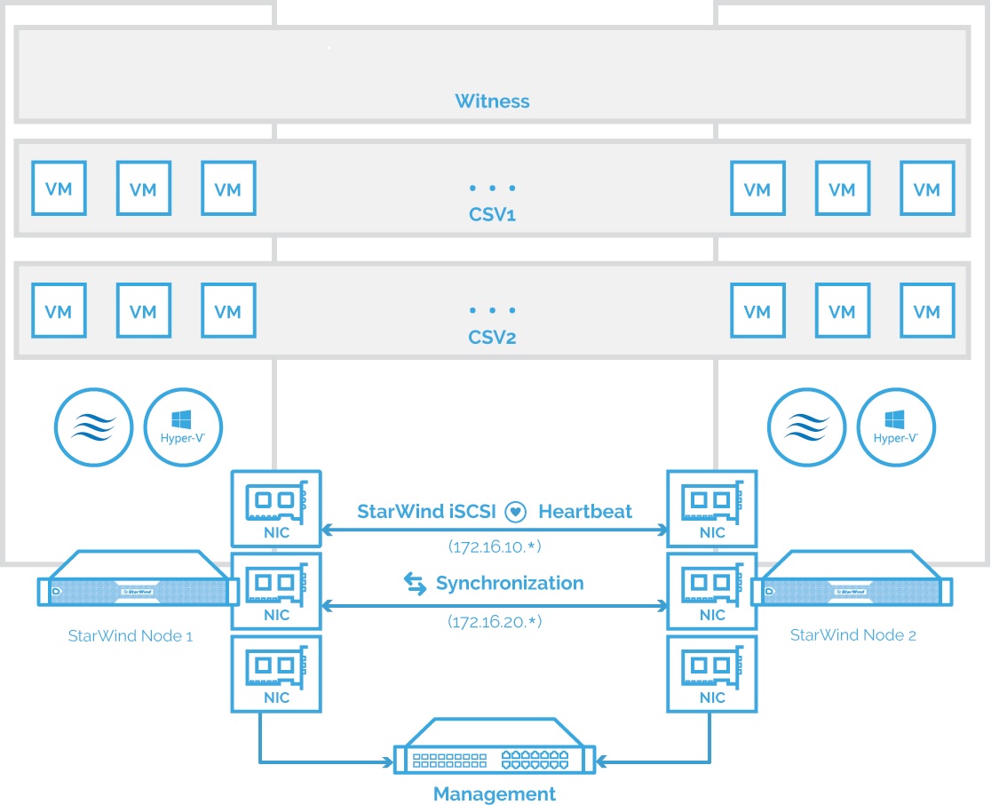
NOTE: Additional network connections may be necessary, depending on the cluster setup and application requirements. For any technical help in regards to configuring the additional networks, please, do not hesitate to contact StarWind support department via online community forum, or via support form (depending on your support plan).
1.Make sure to have a domain controller and the servers added to the domain.
2. Install Failover Clustering and Multipath I/O features along with the Hyper-V role on both servers.
3. Configure network interfaces on each node to make sure that Synchronization and iSCSI/StarWind Heartbeat interfaces are in different subnets and connected according to the network diagram above. In this document, 172.16.10.x subnet is used for iSCSI/StarWind Heartbeat traffic, while 172.16.20.x subnet is used for the Synchronization traffic.
The procedures mentioned above can be performed by following the instructions below.
Pre-Configuring the Servers
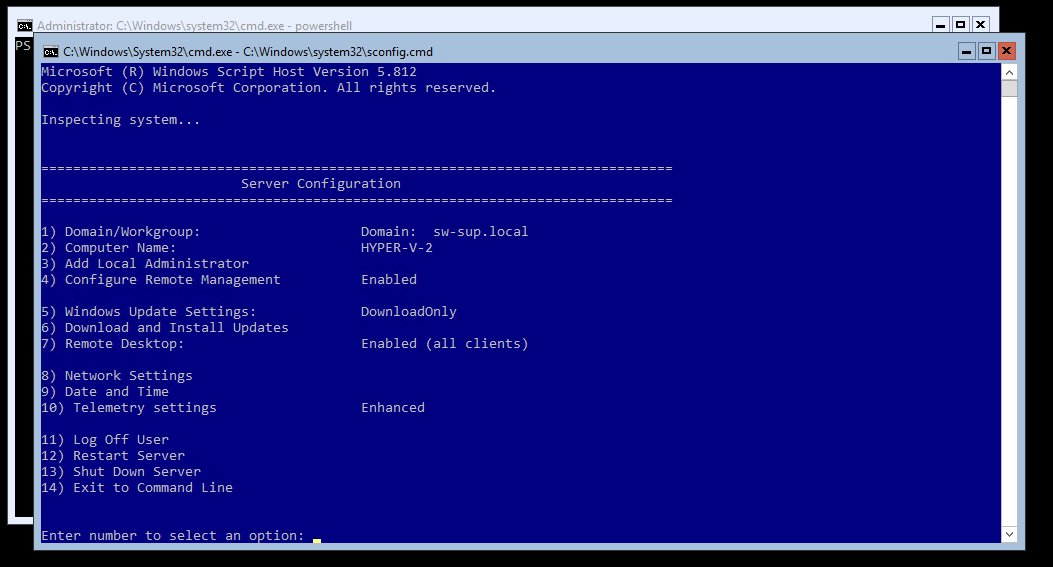
4. Enable Remote Desktop connection to the servers and join them to the domain by selecting the corresponding option in the Server Configuration window.
NOTE: Rename and configure static IP address for network adapters.
5. Run powershell.exe in the Command Prompt to check the network adapters availability in the system:
Get-NetAdapter

6. To change the name and set the static IP for Heartbeat/iSCSI and Synchronization channel, run the next commands via PowerShell:
Get-NetAdapter “Ethernet1” | Rename-NetAdapter –NewName “Sync”

Get-NetAdapter “iSCSI” | New-NetIPAddress –IPAddress 172.16.10.10 –PrefixLength 24

Get-NetAdapter “Ethernet2” | Rename-NetAdapter –NewName “Sync”

Get-NetAdapter “Sync” | New-NetIPAddress –IPAddress 172.16.20.10 –PrefixLength 24
NOTE: The corresponding IP addresses should be configured on the partner node.
7. Alternatively, the network settings can be changed through the sconfig.cmd window. In Network Settings (option 8), select the Index of the NIC which should be edited:

The following actions are possible:
- Set Network Adapter Address – selection between DHCP or Static IP (recommended);
- Set DNS Servers – providing DNS settings;
- Clear DNS Server Settings;
- Return to Main Menu.

Enable Jumbo Frames
8. It is highly recommended to enable jumbo frames (9014) on the Synchronization and iSCSI networks. This can be done via PowerShell in two ways:
- Directly on the Synchronization / iSCSI adapter:
Set-NetAdapterAdvancedProperty –Name “Sync” –RegistryKeyword “*JumboPacket” –Registryvalue 9014

Set-NetAdapterAdvancedProperty –Name “iSCSI” –RegistryKeyword “*JumboPacket” –Registryvalue 9014
- For all adapters available in the system:
Set-NetAdapterAdvancedProperty –Name “*” –RegistryKeyword “*JumboPacket” –Registryvalue 9014

9. Ping each node with jumbo frames (change the asterisk to the corresponding partner node’s IP address):
ping 172.16.20.* -f –l 8900 - for Synchronization network;
ping 172.16.10.* -f –l 8900 - for iSCSI network
Create a Virtual Switch
10. To create a virtual switch on the Management interface, run the next command via PowerShell:
New-VMSwitch –Name “vSwitch” –NetAdapterName “management”
NOTE: The Virtual Switch name must be the same on both nodes.
Disable Firewall
11. To disable firewall, please run the following command via PowerShell on each server:
Get-NetFirewallProfile | Set-NetFirewallProfile –Enabled False
Install Necessary Roles and Features
12. Install Failover Clustering and Multipath I/O features on both servers using PowerShell:
Install-WindowsFeature Failover-Clustering –IncludeAllSubFeature –Restart

Enable-WindowsOptionalFeature –Online –FeatureName MultiPathIO

Enable-MSDSMAutomaticClaim –BusType iSCSI
13. Preparing storage for StarWind devices
NOTE: Please refer to the KB article about recommended RAID settings before proceeding:
https://knowledgebase.starwindsoftware.com/guidance/recommended-raid-settings-for-hdd-and-ssd-disks/
Any storage array intended to be used by StarWind Virtual SAN for storing virtual disk images should meet the following requirements:
- Initialized as GPT;
- Have a single NTFS-formatted partition;
- Have a drive letter assigned.
14. To create a Local Partition for the storage drive, run the commands below in the CMD window:
Diskpart

list disk

select disk X where X is the number of the disk to be processed

online disk

attributes disk clear readonly

convert GPT

create partition Primary

format fs=ntfs label=X quick where X is the name for the Volume

list volume

select volume X

assign letter X where X is the letter for the Volume

list Volume
Downloading, Installing, and Registering the Software
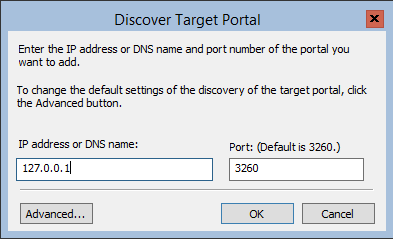
15. Download StarWind VSAN by following the link:
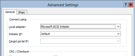
https://www.starwindsoftware.com/starwind-virtual-san
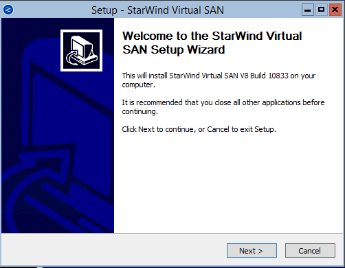
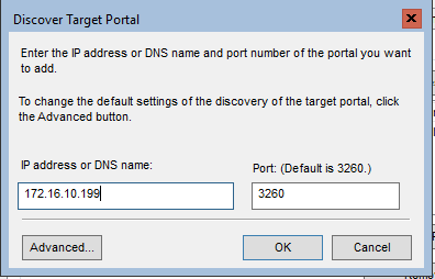
16. Copy the StarWind VSAN installer to both Hyper-V server instances. Launch the downloaded installer on the server where StarWind Virtual SAN or one of its components needs to be installed. The Setup Wizard will appear. Click Next to continue.
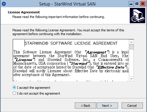
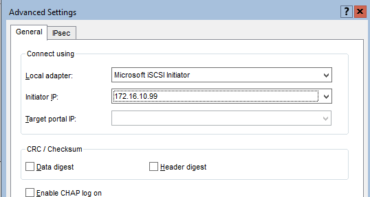
17. Read and accept the License Agreement. Click Next to continue.
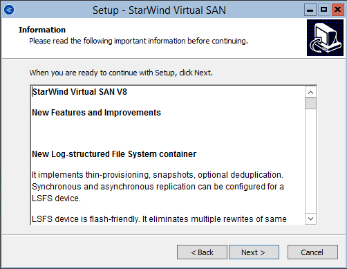
18. Carefully read the information about new features and improvements. Text highlighted in red indicates warnings for users who are updating existing software installations. Click Next to continue.
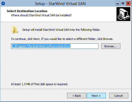
19. Click Browse to modify the installation path if necessary. Click Next to continue.
20. Select the required deployment scenario for StarWind VSAN and click Next to continue.
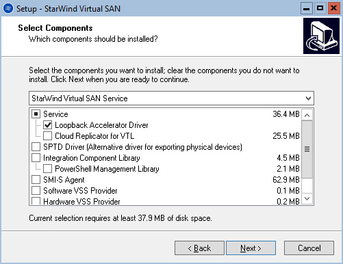
NOTE: This installation type is designed for GUI-less OS editions. The StarWind service is the “core” of the software. It can create iSCSI targets as well as share virtual and physical devices. The service can be operated by StarWind Management Console from any Windows computer or virtual machine in the network that has StarWind Management Console installed or using the Web Client of StarWind Management Console.
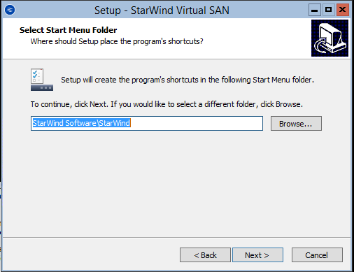
21. Specify the Start Menu Folder. Click Next to continue.
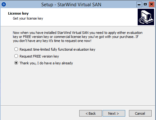
22. When the license prompt appears, choose one of the following options: request either a time-limited fully functional evaluation key, request a free version key or use the commercial license key provided along with the purchase of StarWind Virtual SAN by selecting the corresponding option. Click Next to continue.
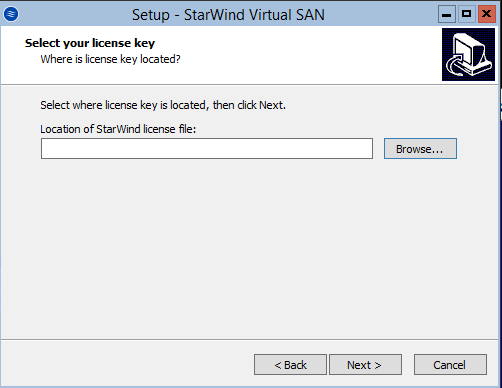
23. Click on the Browse button to locate the license file. Cliсk Next to continue.
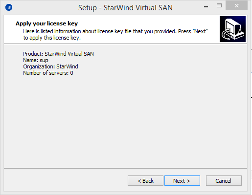
24. Review the licensing information. Click Next to continue.
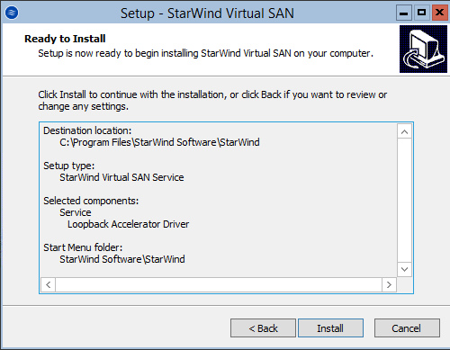
25. Verify the installation settings. Click Back to make any changes. Click Install to continue.
26. Click Finish to close the wizard.
Repeat the steps above on the partner node.
To manage StarWind Virtual SAN deployment on the OS edition with no GUI enabled, StarWind Management Console should be installed on a computer that runs the GUI-enabled OS.
NOTE: In order to allow iSCSI Initiators to discover all StarWind Virtual SAN interfaces, StarWind configuration file (StarWind.cfg) should be changed after stopping the StarWind service on the node where it will be edited.
Locate StarWind Virtual SAN configuration file (the default path is
“C:\Program Files\StarWind Software\StarWind\StarWind.cfg”) and open it via WordPad as Administrator.
Find the <iScsiDiscoveryListInterfaces value=”0”/> string and change the value from 0 to 1 (should look as follows: <iScsiDiscoveryListInterfaces value=”1”/>).
Save the changes and exit WordPad. Once StarWind.cfg is modified and saved, the StarWind service can be started again.
Configuring Shared Storage
NOTE: StarWind Management Console cannot be installed on the operating system without GUI. It can be installed on any GUI-enabled OS, including a desktop version of Windows.
27. Launch StarWind Management Console by double-click on the StarWind tray icon.
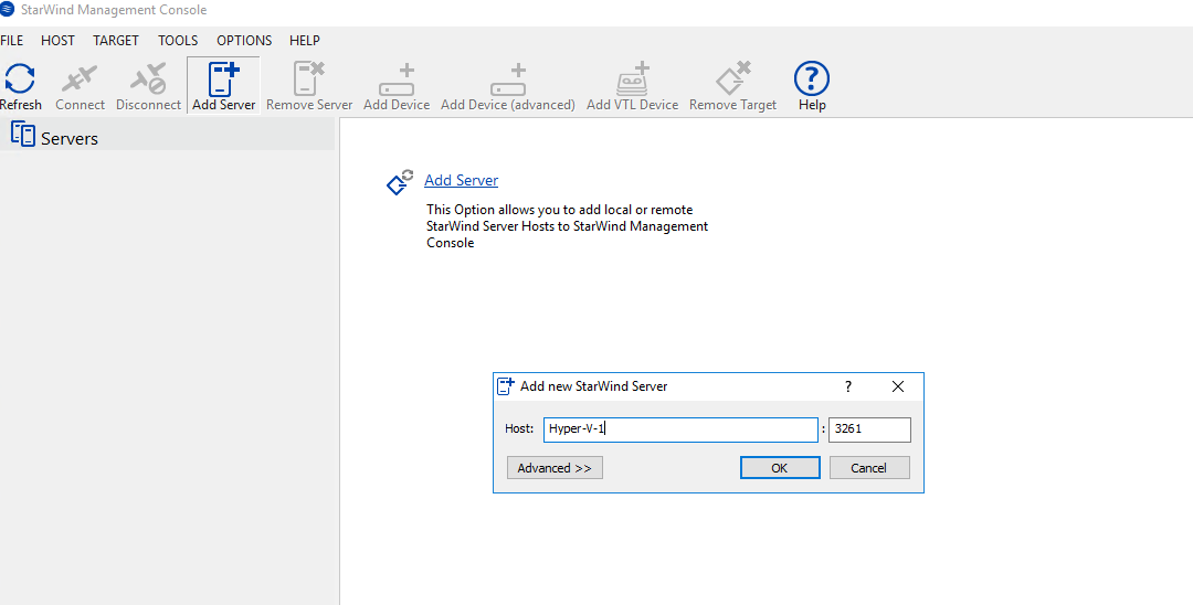
28. To add StarWind VSAN servers to the console, use the Add Server button on the control panel.
29. To add StarWind server, type the Management IP address or servers’ domain name and click OK to continue.
30. Connect to the servers and specify the path for the storage pool.
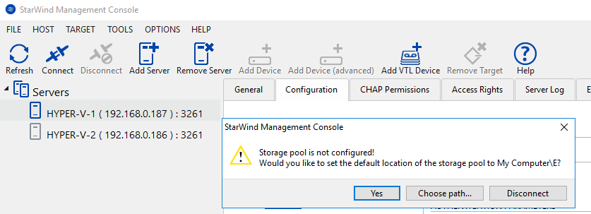
Press Yes to configure the storage pool. If the storage pool destination needs to be changed, press Choose path… and point the file browser to the necessary disk.
NOTE: StarWind Management Console will request the default storage pool location on the server that is connected for the first time. Configure the default storage pool to use one of the volumes prepared earlier. All the devices created through the Add Device wizard will be stored there. If an alternative storage path for StarWind virtual disks is needed, the Add Device (advanced) menu item can be used.
31. Select the StarWind server where the device should be created. Press the Add Device (advanced) button on the toolbar or right-click on the StarWind server.

32. In Add Device Wizard, select Hard Disk Device and click Next to continue.

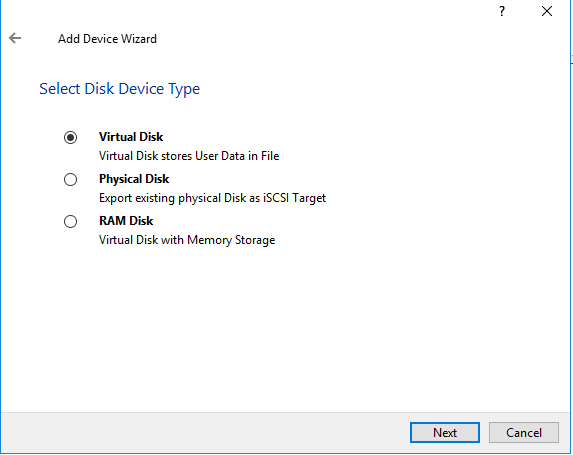
33. Select Virtual Disk and click Next.
34. Specify the StarWind device Name, Location and Size. Click Next.
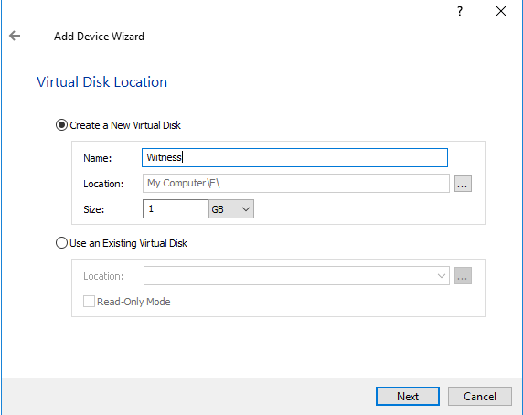
NOTE: It is recommended to create a 1 GB device to avoid long synchronization process. The device can be extended after creation.
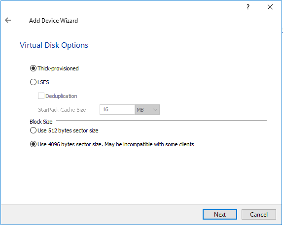
35. Specify the virtual disk options. Choose 4096 bytes sector size for Microsoft Windows.
36. Define the caching policy and specify the cache size (in GB) and click Next to continue.

NOTE: The basic recommendation is to assign 1 GB of L1 cache in Write-Back or Write-Through mode per 1 TB of storage capacity if necessary. Yet, the cache size should correspond to the storage working set of the servers.
37. Define Flash Cache Parameters and Size if necessary. Choose the SSD location in the wizard. Press Next.
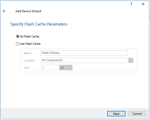
NOTE: The recommended size of the L2 cache is 10% of the initial StarWind device capacity.
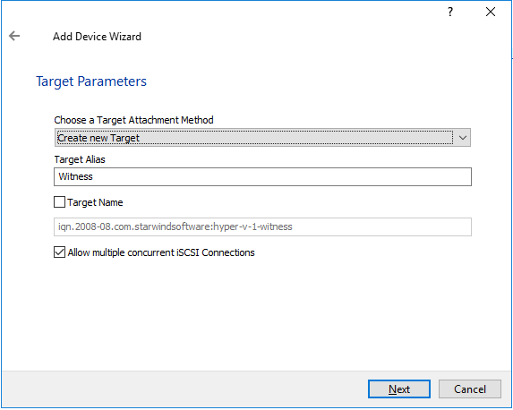
38. Specify the target parameters. Enable the Target Name checkbox to customize the target name. Otherwise, the name will be generated automatically based on the target alias. Click Next to continue.
39. Click Create to add a new device and attach it to the target. Then click Close to finish working with the wizard.
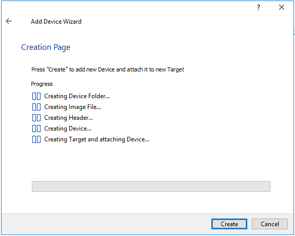
40. Right-click the device that has just been created and select Replication Manager.
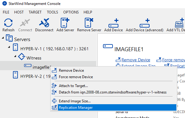
41. The Replication Manager window will appear. Press the Add Replica button.

42. Select Synchronous two-way replication. Click Next to proceed.

43. Specify the partner server IP address or Name. The default StarWind management port is 3261. In case any other port needs to be configured, please type it in the Port Number field.
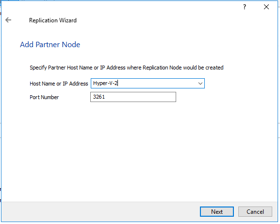
44. Select the Failover Strategy for the HA device. For the purposes of this document, the Heartbeat failover strategy is used. Click Next to continue.
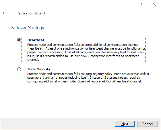
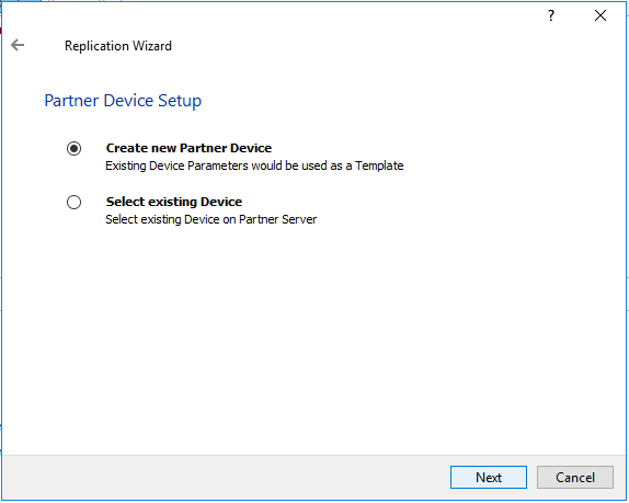
45. Choose Create new Partner Device and click Next.
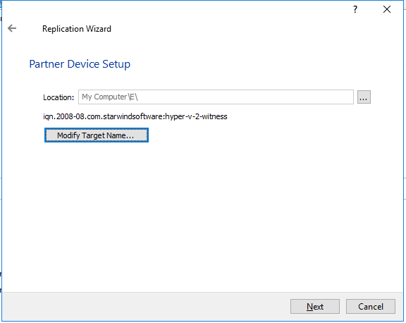
46. Specify the partner device Location if necessary and/or modify the target name of the device. Click Next.
47. Select the Synchronization and Heartbeat networks for the HA device by clicking Change Network Settings.

48. Specify the interfaces for Synchronization and Heartbeat. Press OK. Then click Next.
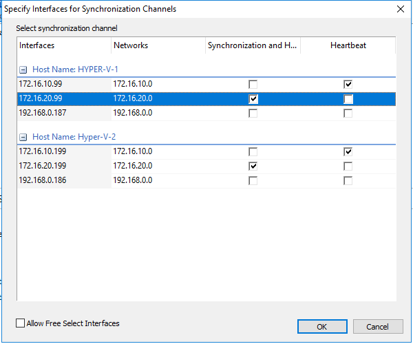
NOTE: It is recommended to configure the Heartbeat and iSCSI channels (in this document 172.16.10.*) on the same interfaces to avoid the split-brain issue. If the Synchronization and Heartbeat interfaces are located on the same network adapter, it is recommended to assign one more Heartbeat interface to a separate adapter
49. Select Synchronize from existing Device for the partner device initialization mode. Click Next.

50. Press the Create Replica button. Then click Close to exit the wizard.
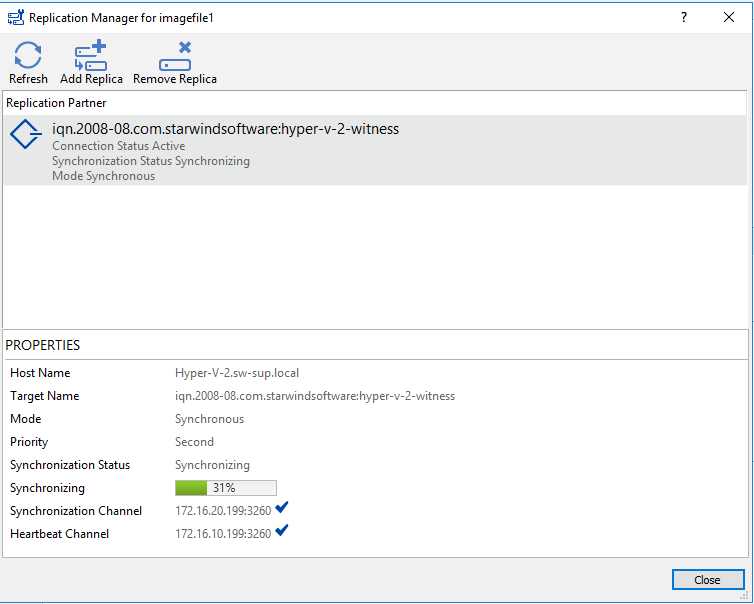
51. The added devices will appear in StarWind Management Console.

52. Repeat the HA device creation steps for any virtual disks that will be used as Cluster Shared Volumes further. Once all the devices are created, the Management Сonsole should look as demonstrated in the screenshot below.

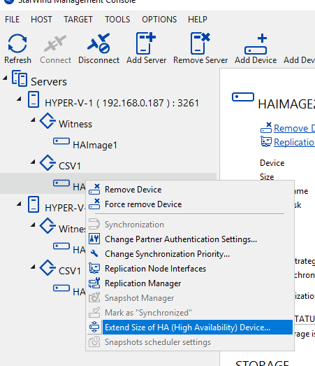
Extending StarWind Device
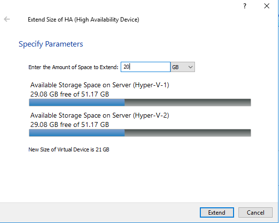
53. Right-click the StarWind device and choose Extend Size of HA (High Availability) Device.
54. Specify the Amount of Space to Extend for this device and press Extend to continue.
55. After extension is completed, the new size of the StarWind HA device will appear in StarWind Management Console as demonstrated in the image below.

Discovering Target Portals
This part describes how to connect the previously created disks which need to be added to the cluster further.
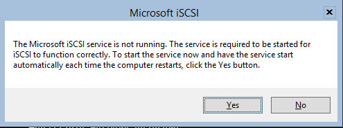
56. Launch Microsoft iSCSI Initiator by executing the following command in the CMD window:
iscsicpl

If the dialog box below appears, press Yes.
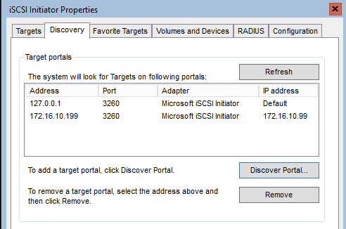
57. In the iSCSI Initiator Properties window, click the Discovery tab.
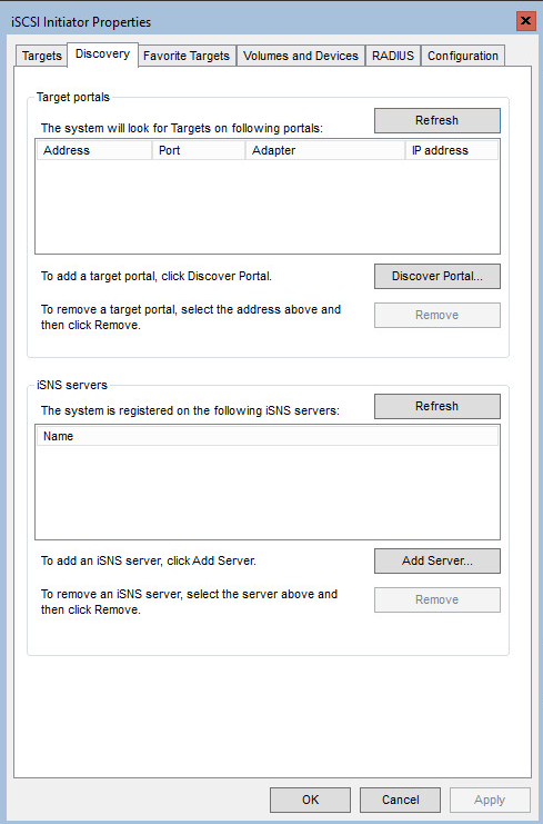
58. Click on the Discover Portal button. The Discover Target Portal dialog appears. In IP address or DNS name field, type in 127.0.0.1.
59. Click on the Advanced button. Select Microsoft iSCSI Initiator as Local adapter and select the Initiator IP (keep it default for 127.0.0.1). Confirm your actions to complete Target Portal Discovery.
60. Click on the Discovery Portal button once again and specify the iSCSI interface IP address of the partner node that will be used to connect the StarWind provisioned targets. Click Advanced.
61. In Advanced Settings, select Microsoft iSCSI Initiator as Local adapter. Select the Initiator IP in the same subnet as the IP address of the partner server from the previous step. Confirm your actions to complete Target Portal Discovery.
62. Now, all Target Portals are added on the first node.
63. Go through the Target Portals Discovery steps on the partner node.
Connecting Targets
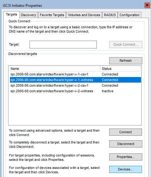
64. Click on the Targets tab. The previously created targets are listed in the Discovered Targets section.
NOTE: If the created targets are not listed, check the firewall settings of the StarWind Server as well as the list of networks served by the StarWind server (go to StarWind Management Console -> Configuration -> Network).
Alternatively, check the Access Rights tab on a corresponding StarWind server in StarWind Management Console for any restrictions implemented.
One of possible reasons could be MS iSCSI Target Server role which uses port 3260. Check the following KB to fix it:
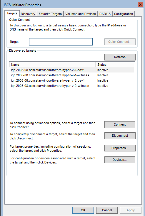
65. In the Targets tab, select the Witness target available from the local server and click Connect. Enable the checkboxes as in the image below. Click Advanced.
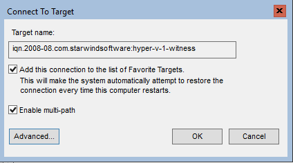
66. In Advanced settings, select Microsoft iSCSI Initiator as Local adapter. Set 127.0.0.1 for the Target portal IP. Confirm your actions.
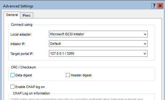
NOTE: It is recommended to connect Witness Device only by loopback (127.0.0.1) address. Do not connect the target to the Witness Device from the StarWind partner node.
67. Select the CSV1 target discovered from the local server and click Connect.
68. Enable checkboxes as in the image below. Click Advanced.

69. Select Microsoft iSCSI Initiator as Local adapter. Select 127.0.0.1 for the Target portal IP. Confirm your actions.

70. In the Targets tab, select the Partner Target from the other StarWind node and click Connect. Enable checkboxes as in the image below and click Advanced.

71. In Advanced settings, select Microsoft iSCSI Initiator as Local adapter. In the Initiator IP dropdown, select the IP address of the host iSCSI link. In Target portal IP, select the corresponding partner’s IP address from the same subnet. Confirm your actions.

72. Repeat the steps above for the remaining HA device targets. The result must be the same as in the screenshot below.

73. Repeat the steps described in this part on another StarWind node, specifying corresponding local and data channel IP addresses. The result must be the same as in the screenshot below.

Multipath Configuration
NOTE: It is recommended to configure other MPIO policies depending on iSCSI channel throughput. For 1 Gbps iSCSI channel throughput, it is recommended to set Failover Only or Least Queue Depth MPIO load balancing policy. For 10 Gbps iSCSI channel throughput, it is recommended to set Round Robin or Least Queue Depth MPIO load balancing policy.
74. Configure the MPIO policy for each target except Witness with the load balance policy of choice. Select the target located on the local server and click Devices.
75. In the Devices dialog, press MPIO.

76. Select the appropriate Load balance policy.
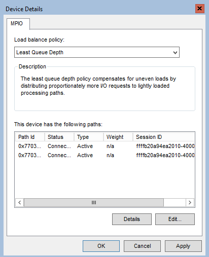
77. For the Witness target, set the load balance policy to Failover Only.
78. Repeat the steps above for configuring the MPIO policy for each remaining device on the current node and on the partner node.
NOTE: In case the Failover Only MPIO policy is used, be sure to check that the local path (127.0.0.1) is set to Active, while the partner connection is set to Standby.
Configuring StarWind Disks on Servers
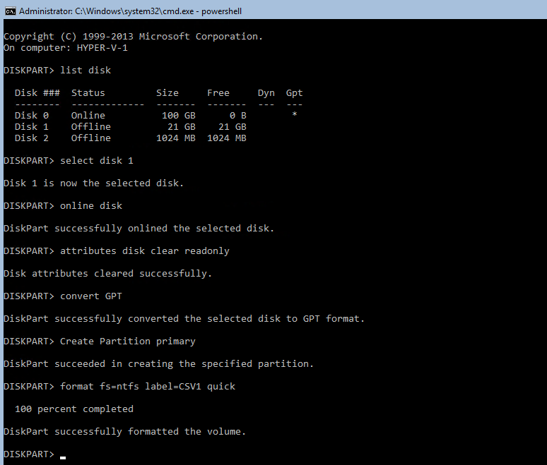
79. To initialize the disks and create the partitions on them use DISKPART. To create a cluster, the disk devices must be visible on both nodes.
Run diskpart in the CMD window:
List disk

Select disk X where X is the number of the disk to be processed

Online disk

Clean

Attributes disk clear readonly

Convert GPT

Create Partition Primary

Format fs=ntfs label=X quick where X is the name of the Volume
Do not assign any letter for the cluster disks.
NOTE: It is recommended to initialize the disks as GPT.
80. Perform the steps above on the partner node.
Creating a Cluster
NOTE: To avoid issues during the cluster configuration validation, it is recommended to install the latest Microsoft updates on each node.
81. Open the Failover Cluster Manager using the desktop version of Windows or a different GUI-based Windows Server and click the Create Cluster link in the Actions section of Failover Cluster Manager.
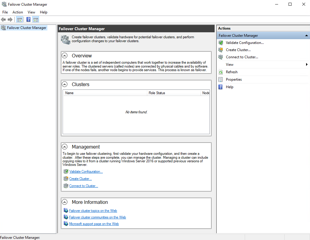
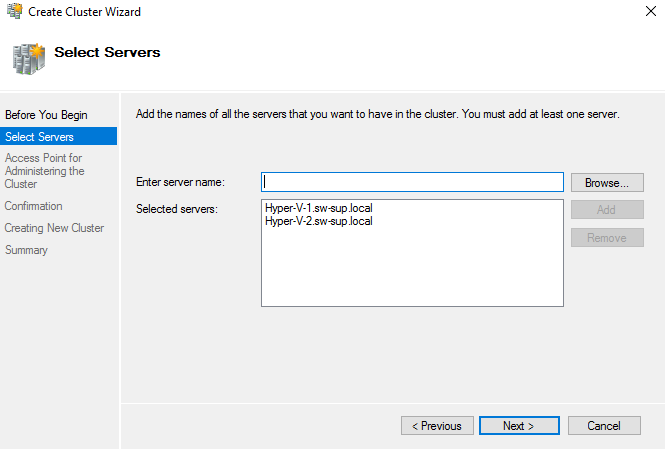
82. Specify the servers to be added to the cluster. Click Next to continue.
83. Validate configuration by passing the cluster validation tests: select Yes and Run all tests. Click Next to continue.

84. Specify the cluster name.
NOTE: If the cluster servers get IP addresses over DHCP, the cluster also gets its IP address over DHCP. If the IP addresses are set statically, you need to set the cluster IP address manually. Click Next to continue.

85. Make sure that all settings are correct. Use the Previous button to make any changes.
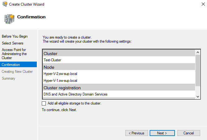
NOTE: If the Add all eligible storage to the cluster checkbox is enabled, the wizard will try to add all disks to the cluster utomatically. The smallest device will be assigned as the Witness. It is recommended to disable this option before you click Next and add Witness manually.
86. Upon completion of the cluster creation, the system displays a report with the detailed information that can be checked by clicking on the View Report button.
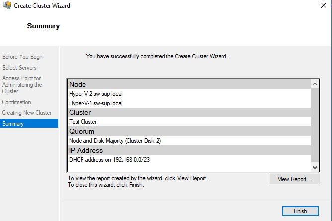
Click Finish to close the wizard.
Adding Storage to the Cluster
Follow the steps below to add the Cluster Shared Volumes (CSV) that are necessary for working with Hyper-V virtual machines.
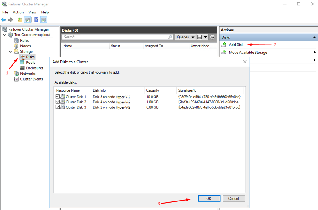
87. In the Failover Cluster Manager, go to Cluster -> Storage -> Disks. Click Add Disk in the Actions panel, choose StarWind disks from the list and confirm the selection.
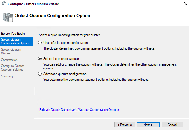
88. To configure the cluster witness disk, right-click on Cluster and proceed to More Actions -> Configure Cluster Quorum Settings.

89. Follow the wizard and use the Select the quorum witness option. Click Next.
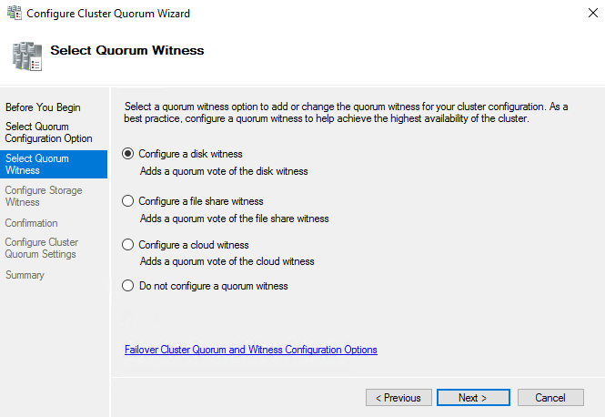
90. Select Configure a disk witness. Click Next.
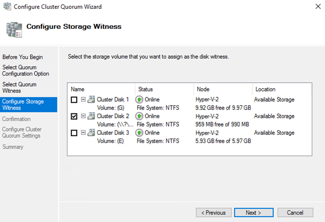
91. Select the Witness disk to be assigned as the cluster witness disk. Click Next and press Finish to complete the operation.
92. In Failover Cluster Manager, under Disks, right-click on the Cluster Disk and select Add to Cluster Shared Volumes.

93. If renaming of the Cluster Shared Volume is required, right-click on the disk and select Properties. Type the new name of the disk and click Apply followed by OK.

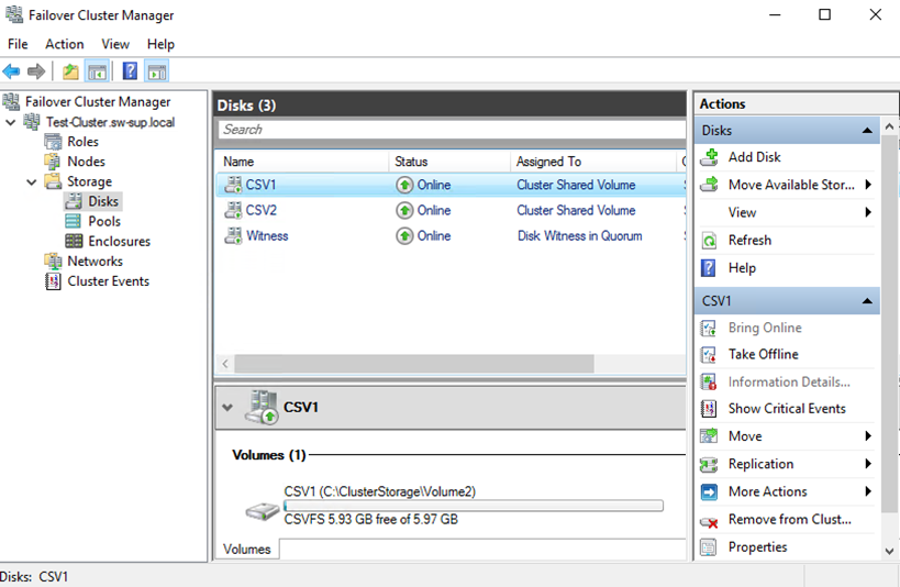
94. Perform the steps above for any other disk in Failover Cluster Manager. The resulting list of disks will look similar to the screenshot below.
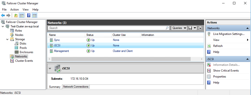
Configuring Cluster Network Preferences
95. In the Networks section of the Failover Cluster Manager, right-click on the network from the list and set its new name if required, identifying the network by its subnet. Apply the change and press OK.
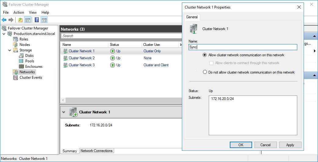
96. Rename other networks as described above, if required.
97. In the Actions tab, click Live Migration Settings. Uncheck the Synchronization network only if the iSCSI network is 10+ Gbps. Apply the changes and click OK.

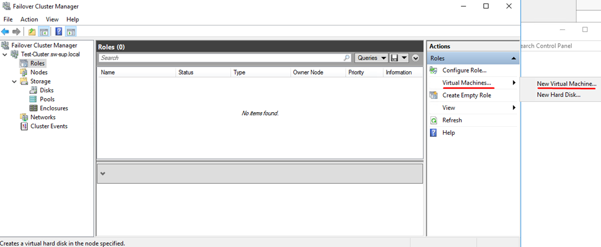
Post-Configuration Tasks
98. Once the disks are added to the Cluster Shared Volumes and the network preferences are set, highly-available virtual machines can be created on the Cluster Shared Volumes. Select Roles and in the Action tab click Virtual Machines -> New Virtual Machine. Complete the wizard.
NOTE: to avoid unnecessary CSV overhead, configure each CSV to be owned by a different cluster node. This node should also be the preferred owner of the VMs running on that CSV.
CONCLUSION
Windows Failover Cluster on the top of Hyper-V Server 2016 is successfully created. This cluster will increase the availability of the services or applications on it, as well as exclude the downtime during the maintenance.
