

StarWind Virtual SAN® AWS EC2 Deployment Guide
- August 07, 2018
- 23 min read
INTRODUCTION
This technical paper covers the Highly Available Shared Storage configuration for multiple roles in Windows Server 2016. It describes how to configure AWS cloud instances, networks in AWS, StarWind Virtual SAN, create Cluster Shared Volumes (CSV), and configure the Failover Cluster Roles.
StarWind Virtual SAN® is a hardware-less storage solution that creates a fault-tolerant and high-performing storage pool built for virtualization workloads by mirroring existing server’s storage and RAM between the participating storage cluster nodes. The mirrored storage resource, in this case, is treated like a local storage. StarWind Virtual SAN ensures simple configuration of highly available shared storage for multiple roles and delivers excellent performance and advanced data protection features.
This guide is intended for experienced Windows Server users, or system administrators. It provides detailed instructions on how to configure HA Shared Storage for Failover Cluster Roles in Windows Server 2016 with StarWind Virtual SAN as a storage provider. It also contains detailed instructions on how to configure AWS EC2 with peering connections, how to create and configure StarWind EC2 instances.
A full set of up-to-date technical documentation can always be found here, or by pressing the Help button in the StarWind Management Console.
For any technical inquiries please visit our online community, Frequently Asked Questions page, or use the support form to contact our technical support department.
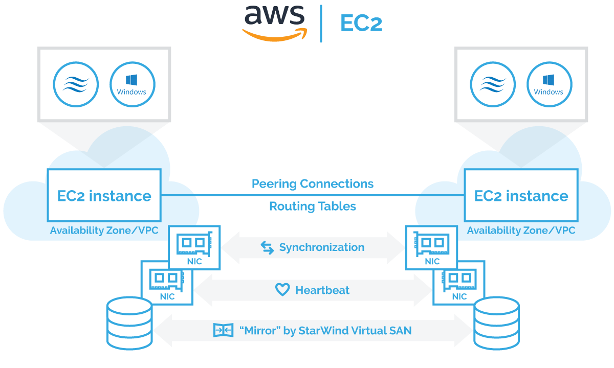
Architecture overview
The proper Virtual Private Cloud (VPC) configuration is a key to successfully realize Microsoft Failover Cluster instances on AWS.
There are two possible ways to deploy StarWind instances in AWS:
- Two StarWind instances within same VPC but in different Availability Zones using routing tables
- Two StarWind instances in different VPCs using peering connection to communicate.
Principal architecture diagram:
Windows Failover Clustering requires Active Directory (AD) as an orchestrator. AD DC (Active Directory Domain Controller) can be either configured as on-premises DC (Domain Controller) with VPN connections to AWS StarWind Instances or/and the virtual instance in AWS EC2 with optional replication to the on-premises domain controller using built-in active directory replication. AWS AD DC best practices can be found following the link.
Configuring AWS EC2 with peering connection between 2 different VPC
1, First, select a region for use in AWS EC2.

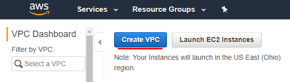
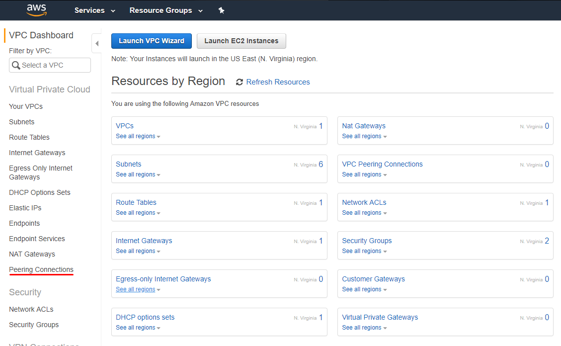
2. Open AWS Management Console and navigate to VPC option in Networking & Content Delivery section.

3. Click on the Create VPC button.
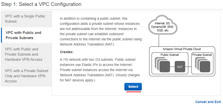
4. Go to VPC with Public and Private Subnets tab and click Select.
5. Specify IP configuration for VPC. Click on Create VPC button.
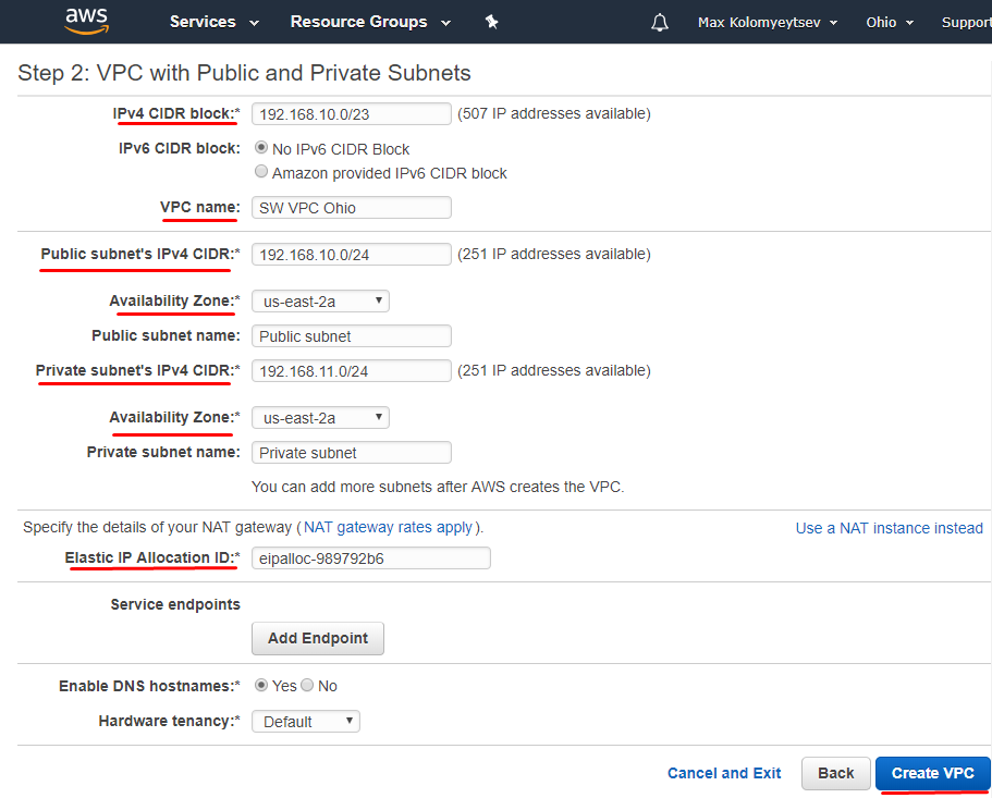
NOTE: All corresponding subnets must be located within the same Availability Zone.
6. Create one more VPC in the different region with subnets configured

7. Create Peering Connections between VPC in different regions. Navigate to VPC dashboard and click on the Peering Connections tab.
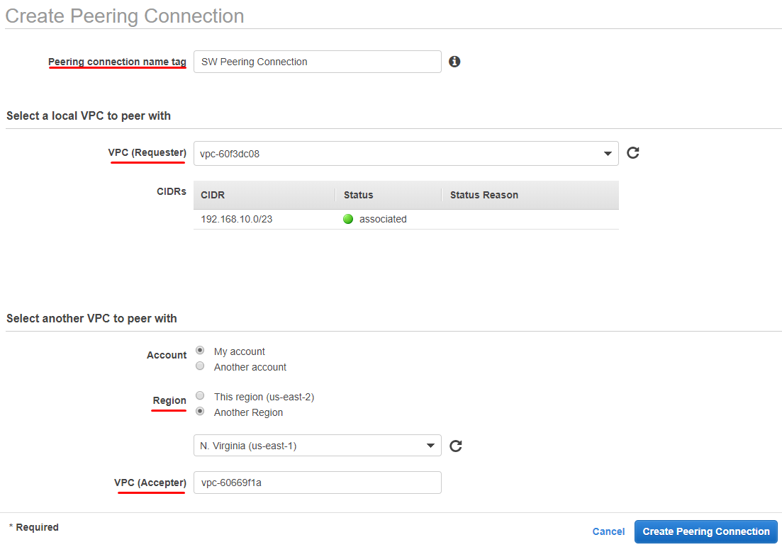
8. In the Create Peering Connection window, specify such parameters as Peering connection name tag, VPC (Requester), Region, VPC (Accepter).
9. Navigate to Peering Connection on the different region and accept connection by clicking on Accept Request.

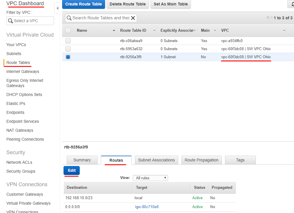
10. Navigate to the Route Tables tab and add an additional Route for VPC connection on each VPC. Click Edit.
11. Click Add another route and specify public and private subnets from partner peering connection.
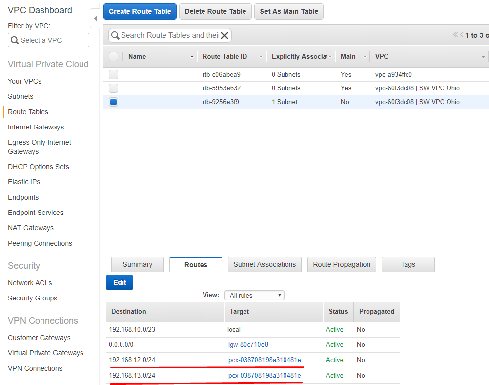
Repeat the same operation on other VPC in the Route Tables.

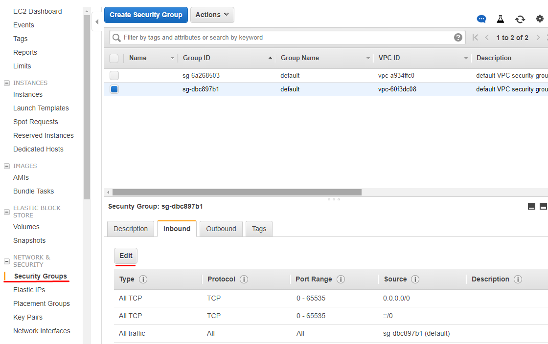
12. To allow RDP and iSCSI connections to the StarWind instances, all TCP or custom TCP rules must be configured in security groups. It is possible to either allow only 3389 (RDP port) and 3260 (iSCSI port) for security groups or allow all inbound/outbound TCP. By clicking Edit in Security Group tab, customize the settings according to the company’s security policy.
VPC and Peering Connections are successfully configured, and this configuration is ready to deploy StarWind instances and configuring HA devices with Failover Clustering.
Configuration of 2 instances in the same VPC is similar. The only change is that StarWind virtual instances are configured between 2 different Availability Zones and communication is allowed by routing tables.
Creating StarWind Instances
13. Open StarWind Virtual SAN page on Amazon Marketplace by following the link.
Select the Instance type: BYOL (Bring your own license) or StarWind Virtual SAN with fees per hour.
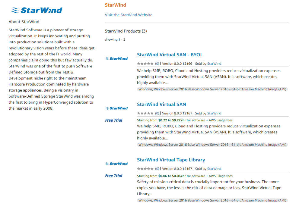
14. Click on the Continue to Subscribe button.

15. Read and accept StarWind EULA. Click on the Continue to Configuration button.

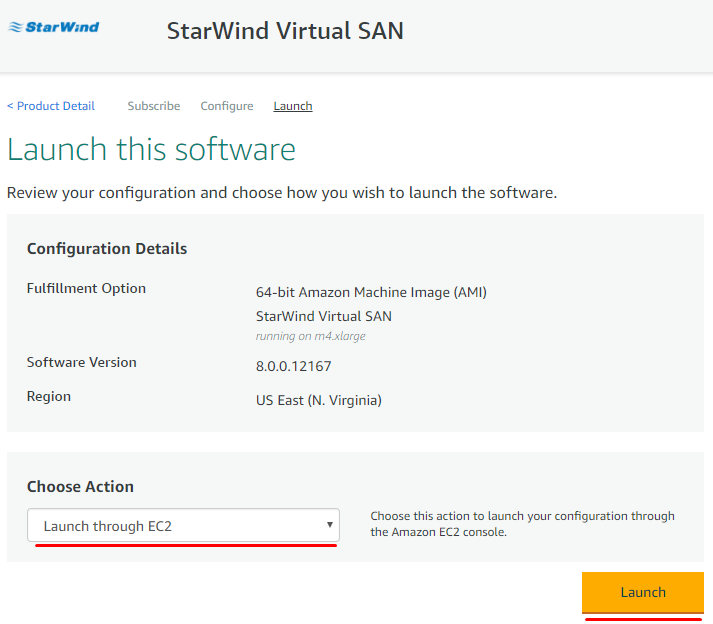
16. Select Region and click on the Continue to Launch button.

17. In the Choose Action section, select Launch through EC2 option from the drop-down list. Click Launch to proceed.
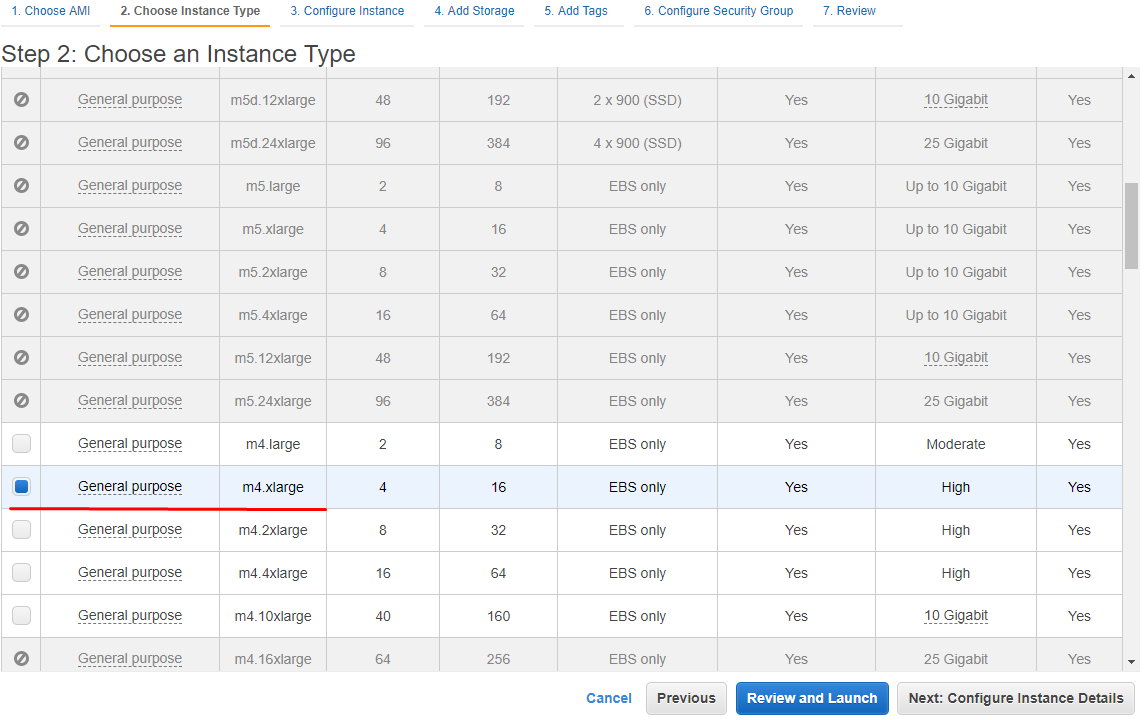
18. Select an Instance Type. StarWind highly recommends to use m4.xlarge type. Click Next: Configure Instance Details to continue.
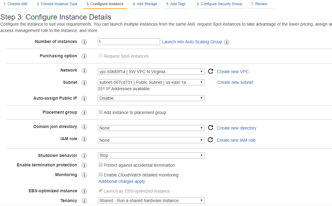
19. Select preconfigured VPC. Review settings and assign IP for Instance and click Next: Add Storage.
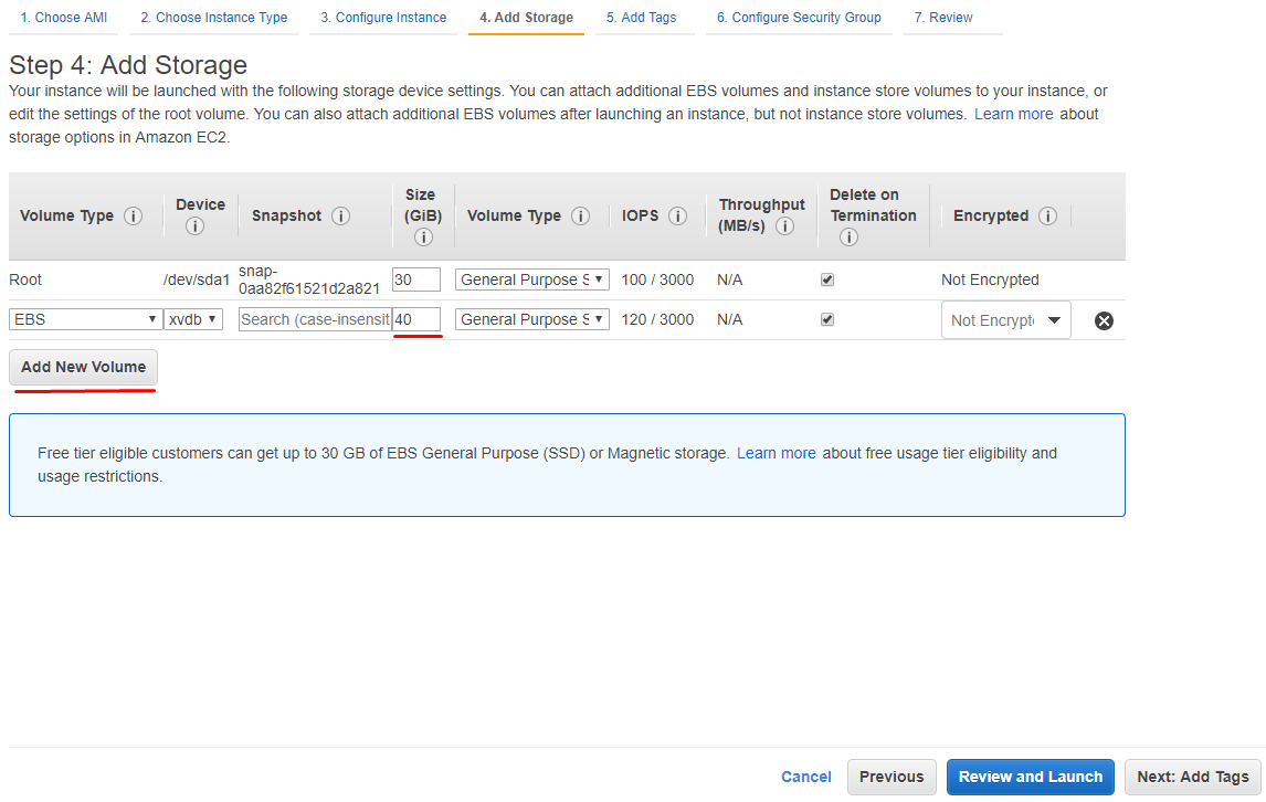
20. Add new volume for StarWind Instance according to the existing needs. Click Next: Add Tags.
21. Assign Tags if needed. Otherwise, this step can be ignored. Click Next: Configure Security Group.
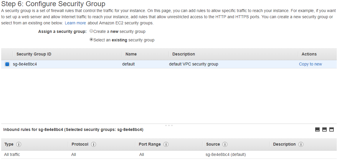
22. Select preconfigured security groups. Click Review and Launch.
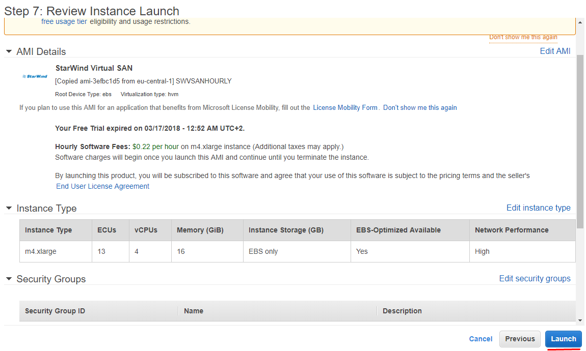
23. Review settings once again and click Launch.
24. Repeat 14-24 steps on different VPC or Availability Zone depending on the scenario.
Manual Installation of StarWind Virtual SAN (optional)
StarWind Virtual SAN can be installed on existing Windows-based EC2 Instances via setup wizard.
25. Download StarWind setup executable file from StarWind website by following this link: https://www.starwind.com/registration-starwind-virtual-san
NOTE: The setup file is the same for x86 and x64 systems, as well as for all Virtual SAN deployment scenarios.
26. Launch the downloaded setup file on the server where installation of StarWind Virtual SAN or one of its components is planned. The setup wizard will appear.
27. Read and accept the License Agreement.

28. Carefully read the information about new features and improvements. Read the text that indicates warnings for users who update existing software installations. Click Next to continue.

29. Click Browse to modify the installation path if necessary. Click Next to continue.

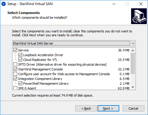
30. Select the following components for the minimum setup:
- StarWind Virtual SAN Service
StarWind Service is the “core” of the software. It can create iSCSI targets as well as share virtual and physical devices. The service can be managed from StarWind Management Console on any Windows computer or virtual machine is the network. Alternatively, the service can be managed from StarWind Web Console which is deployed separately. - StarWind Management Console
Management Console is the Graphic User Interface (GUI) part of the software that controls and monitors all storage-related operations (e.g., allows users to create targets and devices on StarWind Virtual SAN servers connected to the network). Click Next to continue.
31. Specify the Start Menu folder. Click Next to continue.

32. Tick the Create a desktop icon checkbox to create a desktop icon and click Next to continue.

33. When the license prompt appears, choose one of the following options: request either a time-limited fully functional evaluation key, request a free version key or use the commercial license key obtained along with the purchase of StarWind Virtual SAN by selecting the corresponding option. Click Next to continue.

34. Click Browse to locate the license file. Click Next to continue.

35. Verify the installation settings. Click Back to make any changes or Install to continue.

36. Select the corresponding checkbox to launch the StarWind Management Console right after the setup wizard is closed. Click Finish to close the wizard.

37. Repeat the installation steps on the partner node.
Configuring StarWind EC2 Instances
38. Make sure that there is a domain controller and that configured servers are joined to the domain.
39. Install Failover Clustering, Multipath I/O features on both servers. That can be done through Server Manager (Add Roles and Features menu item).
Configure network interfaces on each node making sure that Synchronization and iSCSI/StarWind Heartbeat interfaces are in different subnets. In this document, 192.168.10.x/192.168.12.x subnet is used for iSCSI/StarWind Heartbeat traffic, while 192.168.11.x/192.168.13.x subnet is used for the Synchronization traffic.
40. In order to allow iSCSI Initiators to discover all StarWind Virtual SAN interfaces, StarWind configuration file (StarWind.cfg) should be changed after stopping StarWind Service on the node where it will be edited.
Locate StarWind Virtual SAN configuration file (the default path is: C:\Program Files\StarWind Software\StarWind\StarWind.cfg ) and open it via Wordpad as Administrator.
Find the <iScsiDiscoveryListInterfaces value=”0”/> string and change the value from 0 to 1 (should look as follows: <iScsiDiscoveryListInterfaces value=”1”/>). Save the changes and exit Wordpad. Once StarWind.cfg is changed and saved, StarWind service can be started.
Enabling Multipath Support
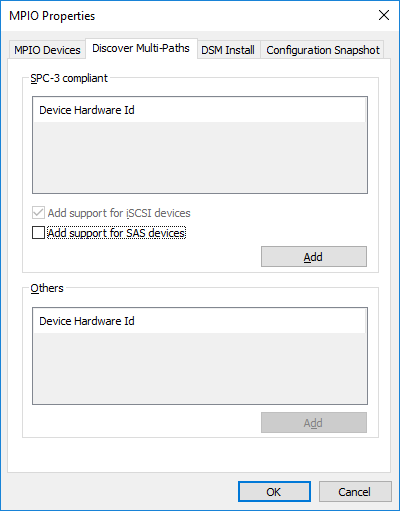
41. On cluster nodes, open the MPIO manager: Start->Administrative Tools->MPIO.
42. Go to the Discover Multi-Paths tab.
43. Tick the Add support for iSCSI devices checkbox and click Add.
44. Optionally, click Yes to restart the server.
NOTE: Repeat the procedure on the second server.
Configuring Shared Storage
Configuring Shared Storage
45. Launch StarWind Management Console by double-clicking the StarWind tray icon.
NOTE: StarWind Management Console cannot be installed on an operating system without a GUI. It can be installed on Windows Desktop 7, 8, 8.1, 10, and Windows Server 2008 R2, 2012, 2012 R2, 2016 editions.

If StarWind Service and Management Console are installed on the same server, the Management Console will automatically add the local StarWind node to the console after the first launch. Then, Management Console automatically connects to it using default credentials. To add remote StarWind servers to the console, use the Add Server button on the control panel.
46. StarWind Management Console will ask to specify the default storage pool on the server to connect to for the first time. Please configure the default storage pool to use one of the volumes prepared earlier. All the devices created through the Add Device wizard will be stored on it. If alternative storage pool is planned to use for the StarWind virtual disks, please use the Add Device (advanced) menu item.

Press the Yes button to configure the storage pool. If storage pool destination should be changed, press Choose path… and point the browser to the necessary disk.
NOTE: Each array used by StarWind Virtual SAN to store virtual disk images should meet the following requirements:
- initialized as GPT;
- have a single NTFS-formatted partition;
- have a drive letter assigned.
The steps below, describe how to prepare an HA device for Witness drive. Other devices should be created the same way.
47. Select one of two StarWind servers to start the device creation and configuration.
48. Press the Add Device (advanced) button on the toolbar.
49. Add Device Wizard will appear. Select Hard Disk Device and click Next.
50. Select the virtual disk and click Next.
51. Specify the virtual disk Name, Location and Size. Click Next.

52. Select the type of the StarWind device (Thick-provisioned or LSFS), specify the block size, and click Next.

53. Define the caching policy, specify the cache size, and click Next.

NOTE: It is recommended to assign 1 GB of L1 cache in Write-Back or Write-Through mode per 1 TB storage capacity if necessary.
54. Define the Flash Cache Parameters policy and size if necessary. Choose the SSD location in the wizard. Click Next to continue.

NOTE: The recommended size of the L2 cache is 10% of the initial StarWind device capacity.
55. Specify the Target Parameters. Select the Target Name checkbox to enter a custom name of the target. Otherwise, the name will be generated automatically based on the target alias. Click Next to continue.

56. Click Create to add a new device and assign it to the target. Then, click Close.
57. Right-click the Servers field and click the Add Server button. Add a new StarWind Server which will be used as the partner HA node.

58. Right-click on the newly created device and select Replication Manager.

59. Press the Add Replica button in the Replication Manager window. Select Synchronous two-way replication option and click Next to proceed.

60. Specify the partner server IP address. Click Next.

NOTE: The Default StarWind management port is 3261. If a different port is configured, make sure to change the Port Number value parameter accordingly.
61. Select the Heartbeat failover strategy and click Next.

62. Choose Create new Partner Device option and click Next.

63. Specify the Partner Device Location or the target name of the device if necessary. to continue.

64. Select Synchronization and Heartbeat channels for the HA device by clicking the Change Network Settings button.

65. Specify the interfaces for Synchronization and Heartbeat. Click OK. Then click Next.

NOTE: It is recommended to configure Heartbeat and iSCSI channels on the same interfaces to avoid the split-brain issue. If Synchronization and Heartbeat interfaces are located on the same network adapter, it is recommended to assign one more Heartbeat interface to a separate adapter.
NOTE: Check Allow Free Select Interfaces to select networks in different subnets.
66. Select Synchronize from existing Device option as a partner device initialization mode and click Next.

67. Press the Create Replica button. Then click Close.
68. The added devices will appear in StarWind Management Console.
69. Repeat the steps above to create other virtual disks if necessary.
Once all devices are created, the Management Console should look as follows:

Discovering Target Portals
This section describes how to discover Target Portals on each StarWind node.
70. Launch Microsoft iSCSI Initiator on the first StarWind node: Start > Administrative Tools > iSCSI Initiator or iscsicpl from the command line interface. The iSCSI Initiator Properties window will appear.
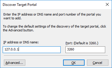
71. Navigate to the Discovery tab. Click the Discover Portal button. In Discover Target Portal dialog box, enter the local IP address – 127.0.0.1 in the corresponding field.
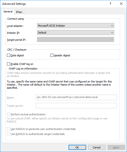
72. Click the Advanced button, select Microsoft iSCSI Initiator as a Local adapter and keep Initiator IP as it is set by default. Press OK twice to complete the Target Portal discovery.
73. Click the Discover Portal button once again.
74. In the Discover Target Portal dialog box, enter the iSCSI IP address of the partner node and click the Advanced button.

75. Select Microsoft iSCSI Initiator as a Local adapter and select the initiator IP address from the same subnet. Click OK twice to add the Target Portal.

76. Target portals are added on the local node.

77. Go through the same steps on the partner node.
78. All target portals are added to the partner node.

Connecting Targets
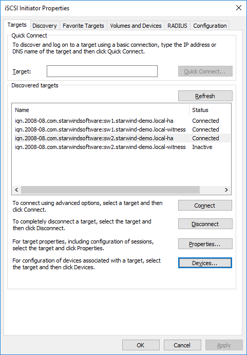
79. Launch Microsoft iSCSI Initiator on the first StarWind node and click on the Targets tab. The previously created targets should be listed in the Discovered targets section.

NOTE: If the created targets are not listed, check the firewall settings of the StarWind Server and the list of networks served by the StarWind Server (go to StarWind Management Console -> Configuration -> Network).
80. Select a target for the Witness device discovered from the local server and click Connect.
81. Tick the checkboxes as shown in the image below and click Advanced….

82. Select Microsoft iSCSI Initiator in the Local adapter field. Select 127.0.0.1 / 3260 option in the Target portal IP list. Click OK twice to connect the target.

NOTE: It is recommended to connect the Witness device only by loopback (127.0.0.1) address. Do not connect the target to the Witness device from the partner StarWind node.
83. Select the target for the SMB share device discovered from the local server and click Connect.
84. Tick the checkboxes like in the image below and click Advanced….

85. Select Microsoft iSCSI Initiator option in the Local adapter field. Select 127.0.0.1 / 3260 option in the Target portal IP area. Click OK twice to connect the target.

Select the target for the HA device discovered from the partner StarWind node and click Connect.
86. Tick the checkboxes like in the image below and click Advanced….

87. Select Microsoft iSCSI Initiator in the Local adapter text field. In the Target portal IP, select the IP address for the iSCSI channel on the partner StarWind Node and the Initiator IP address from the same subnet. Click OK twice to connect the target.

88. Repeat the actions mentioned above for all the HA device targets. The result should look like in the picture below.

89. Repeat the steps described in this section on the partner StarWind node, specifying corresponding IP addresses for the iSCSI channel. The result should look like in the screenshot below.

Multipath Configuration
NOTE: It is recommended to configure different MPIO policies depending on the iSCSI channel throughput. For 1 Gbps iSCSI channel throughput, Failover Only MPIO policy is advised. For 10 Gbps iSCSI channel throughput, it is recommended to set Round Robin or Least queue depth MPIO policy.
90. With Failover Only MPIO policy, it is recommended to set localhost (127.0.0.1) as the active path. Select a target located on the local server and click Devices…
91. The Devices dialog will appear. Click MPIO….

92. Select Fail Over Only load balance policy, and then designate the local path as active.

93. It is possible to verify that 127.0.0.1 is the active path by selecting it from the list and clicking Details.

94. Repeat the same steps for each device on both nodes.
95. Initialize the disks and create partitions on them using the Disk Management snap-in. The disk devices are required to be initialized and formatted on both nodes in order to create the cluster.
NOTE: It is recommended to initialize the disks as GPT.
Creating a Cluster
NOTE: To avoid issues during the cluster validation configuration, it is recommended to install the latest Microsoft updates on each node.
96. Open the Server Manager. Select the Failover Cluster Manager item from the Tools menu.
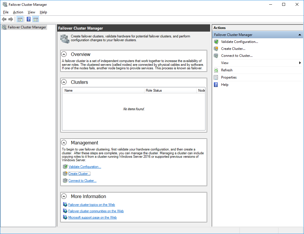
97. Click the Create Cluster link in the Actions section of the Failover Cluster Manager.
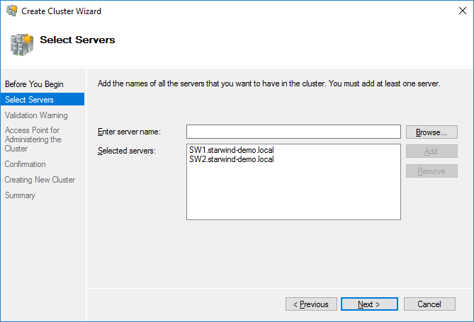
98. Specify the servers which should be added to the cluster. Сlick Next to continue.
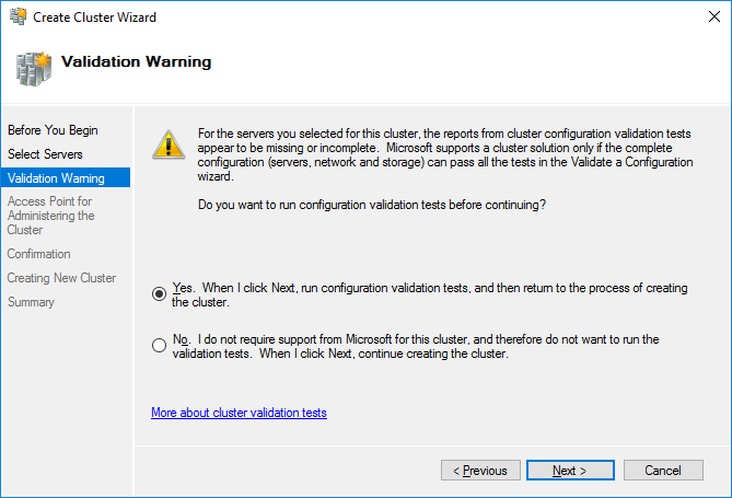
99. Validate the configuration by running the cluster validation tests: select Yes option and click Next to continue.
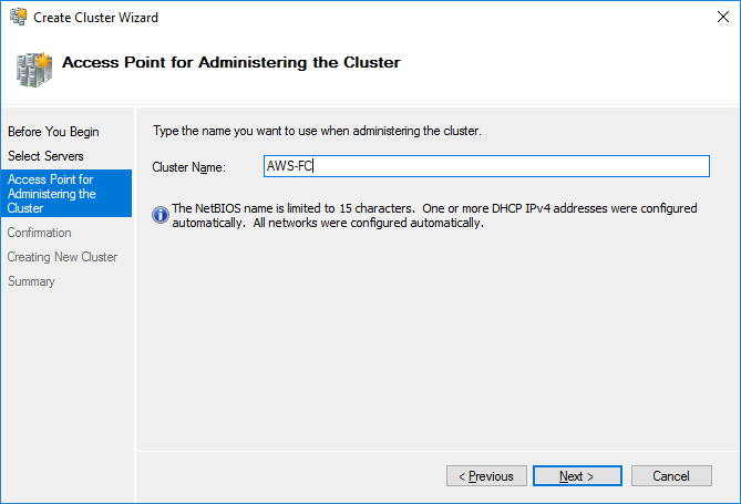
100. Specify the cluster name.
NOTE: If the cluster servers get IP addresses over DHCP, the cluster also gets its IP address over DHCP. If the IP addresses are set statically, set the cluster IP address manually. Click Next to continue.
101. Make sure that all the settings are correct. Click Previous to change the settings (if necessary):
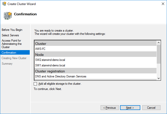
NOTE: If checkbox Add all eligible storage to the cluster is ticked, the wizard will add all disks to the cluster automatically. The device with the smallest storage volume will be assigned as a Witness. It is recommended to uncheck it before clicking Next and add cluster disks and the Witness drive manually.
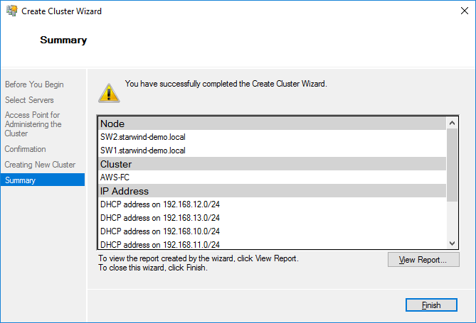
102. The process of cluster creation starts. Upon completion, the system displays a summary with detailed information. Click Finish to close the wizard.
Configuring the Witness Device
103. Open Failover Cluster Manager.
104. Go to Cluster->Storage -> Disks.
105. Click Add Disk in the Actions panel, choose StarWind disks from the list, and click OK.
106. To configure the Witness drive, right-click Cluster->More Actions->Configure Cluster Quorum Settings, follow the wizard, and use the default quorum configuration.

CONCLUSION
This guide describes the configuration of a 2-node fault-tolerant Microsoft Failover Cluster in AWS within the same VPC and multi-region VPC with StarWind Virtual SAN as a backbone for the HA shared storage. Now it is possible to either deploy SQL Failover Cluster Instances (FCI) or even Highly Available SMB-based file shares.
