

StarWind Virtual HCI Appliance: Configuration Guide for VMware vSphere [ESXi]
- November 26, 2024
- 29 min read
- Download as PDF
Annotation
Relevant products
StarWind Virtual HCI Appliance (VHCA)
Purpose
This document outlines how to configure a StarWind Virtual HCI Appliance (VHCA) based on VMware vSphere [ESXi], with VSAN running as a Controller Virtual Machine (CVM). The guide includes steps to prepare ESXi hosts for clustering, configure physical and virtual networking, and set up the Virtual SAN Controller Virtual Machine.
Audience
This technical guide is intended for storage and virtualization architects, system administrators, and partners designing virtualized environments using StarWind Virtual HCI Appliance (VHCA).
Expected result
The end result of following this guide will be a fully configured high-availability StarWind Virtual HCI Appliance (VHCA) powered by VMware vSphere [ESXi] that includes virtual machine shared storage provided by StarWind VSAN.
Prerequisites
Prior to configuring StarWind Virtual HCI Appliance (VHCA), please make sure that the system meets the requirements, which are available via the following link:
https://www.starwindsoftware.com/system-requirements
Recommended RAID settings for HDD and SSD disks:
https://knowledgebase.starwindsoftware.com/guidance/recommended-raid-settings-for-hdd-and-ssd-disks/
Please read StarWind Virtual SAN Best Practices document for additional information:
https://www.starwindsoftware.com/resource-library/starwind-virtual-san-best-practices
Solution Diagram:

Prerequisites:
1. 2 servers with local storage, which have direct network connections for Synchronization and iSCSI/StarWind heartbeat traffic.
2. Servers should have local storage available for VMware vSphere [ESXi] and StarWind VSAN Controller Virtual Machine. CVM utilizes local storage to create replicated shared storage connected to VMware vSphere [ESXi] nodes via iSCSI.
3. StarWind HA devices require at least 2 separate network links between the nodes. The first one is used for iSCSI traffic, the second one is used for Synchronization traffic.
Note. The network interfaces on each node for Synchronization and iSCSI/StarWind heartbeat interfaces should be in different subnets and connected directly according to the network diagram above. Here, the 172.16.10.x subnet is used for the iSCSI/StarWind heartbeat traffic, while the 172.16.20.x subnet is used for the Synchronization traffic.
Hardware Configuration
Access the BIOS on each server:
1. Change “Boot mode select” to [UEFI]
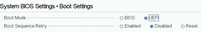
2. Enable AC Power Recovery to On;

3. Set System Profile Settings to Performance;

4. Disable Patrol Read in case of SSD disks;

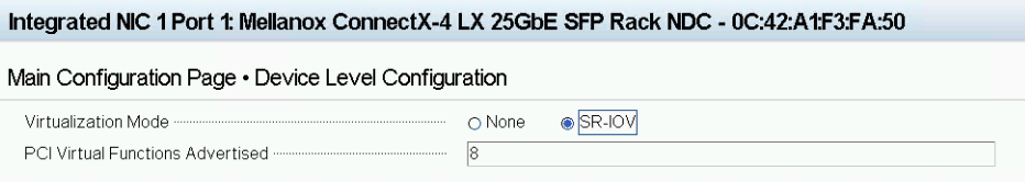
5. Enable SR-IOV for network cards;
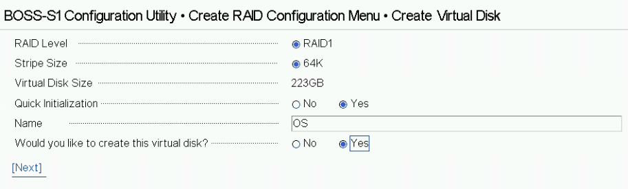
 6. Configure the storage for OS and for data, or single RAID for OS and Data according to Supported RAID configurations here.
Settings for OS RAID1:
Virtual disk name: OS
Disk cache policy: Default (enabled by default)
Write policy: Write Through
Read policy: No read ahead
Stripe Size: 64K
Storage for data:
Find supported RAID configurations for main data storage here.

Files for StarWind vHCI configuration:
The StarWind files for vHCI configuration should be downloaded to Windows machine, which will be used for configuration. Run “StarWind Folders.ps1” script to form StarWind Files folder.
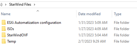
Structure of the StarWind Files folder:
C:\StarWind Files
C:\StarWind Files\ESXi Automatization configuration
C:\StarWind Files\ISOs
C:\StarWind Files\StarWindOVF
C:\StarWind Files\Temp
Scripts that are included in the “StarWind Folders.ps1” script.
C:\StarWind Files\ESXi Automatization configuration\Esxi+configuration.ps1
C:\StarWind Files\Temp\ISOs Download.ps1
ISOs Download.ps1 allows to download the customized ISOs and OVF for vHCI configuration:
Windows 2019/2022
ESXi 7/8 / vCenter 7/8
StarWind VSAN for vSphere OVF
The Esxi+configuration.ps1 allows performing the ESXi configuration.
ESXi Configuration Part:
Node 1
1. Start the “C:\StarWind Files\ESXi Automatization configuration\Esxi+configuration.ps1” with administrator rights.
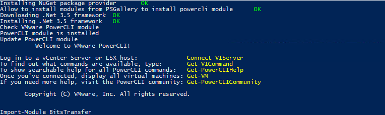
2. Installation of the components:
Nuget provider
PSGallery for Modules
.net 3.5
PowerCLI Module
BitsTransfer Module

3. ESXi server details:
IP address/user/password
![]()
4. Connection to the server

Type “a” to perform the operation.
5. Choose [1] to change the ESXi server name:

The specific name for ESXi could be set when you choose it:
![]()
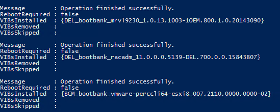
6. Set the ‘CommunitySupported’ level for ESXi and install VIBs.
![]()

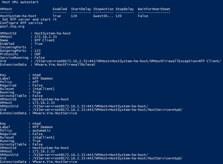
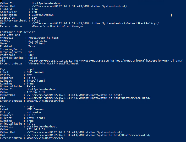
7. Autostart for ESXi server and default NTP server
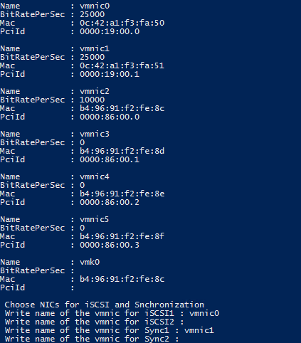
8. Choose network interfaces for iSCSI and Synchronization.
For 2 node configuration ( 1 iSCSI and 1 Sync ) we need to choose iSCSI1 and Sync1
For 3 node configuration ( 2 iSCSI and 2 Sync ) we need to choose iSCSI1, iSCSI2, and Sync1, Sync2
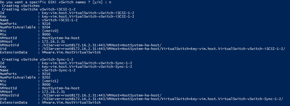
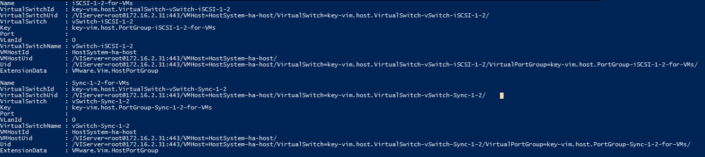
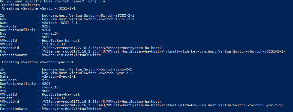
9. The script will create vSwitches, VMKernel, and Port Groups with default StarWind names if you did not
choose the ‘specific ESXi vSwitch name’. When ‘specific ESXi vSwitch name’ is chosen, vSwitches,
VMKernel, Port Groups, and iSCSI discovery will need specific names and IP addresses.
![]()
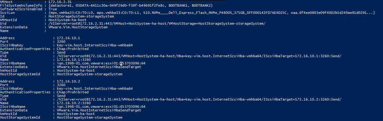
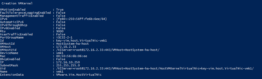
10. VMKernel will be created automatically in case of default names.
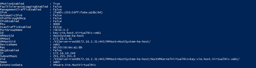
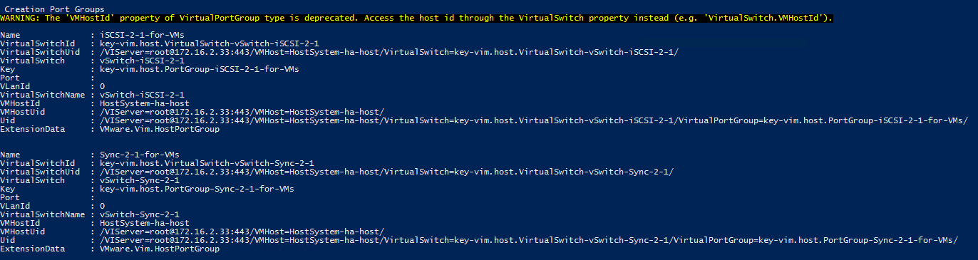
11.Port Groups will be created automatically in case of default names.
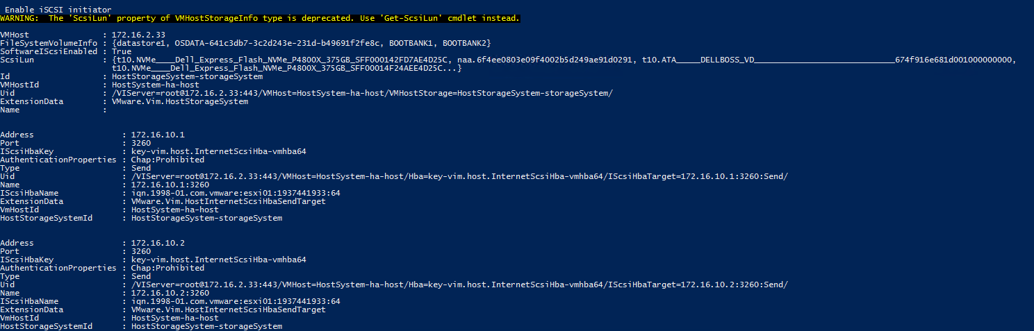
12. iSCSI initiator and iSCSI discovery IP addresses will be created automatically in case of default names.
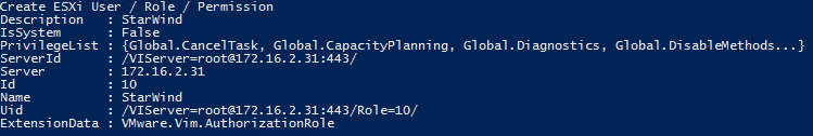
13. StarWind ESXi user for ProActive monitoring creation.
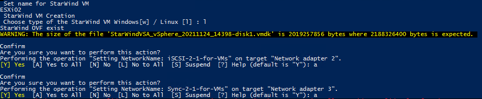
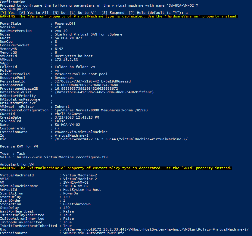
14. StarWind Virtual Machine installation. Choose “l” for StarWind Virtual SAN (vSAN) for vSphere.
It is possible to change the default ESXi name by specifying a name for Virtual Machine.
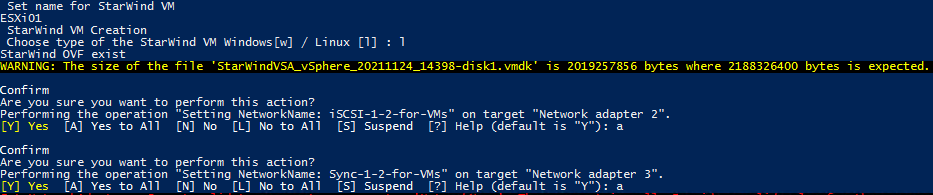
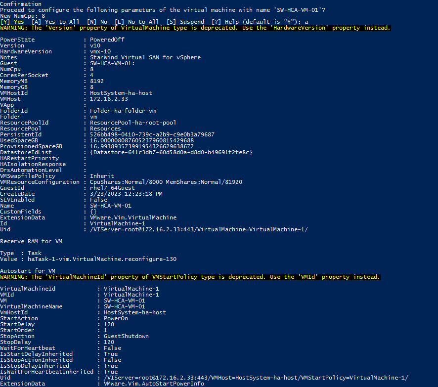
Note: OVF will be downloaded if it is not present. CPU and RAM memory will be configured according to our best practices.
Storage drives for StarWind devices should be added manually.
Node 2
1. Start the “C:\StarWind Files\ESXi Automatization configuration\Esxi+configuration.ps1” with administrator rights.
2. Installation of the components:
Nuget provider
PSGallery for Modules
.net 3.5
PowerCLI Module
BitsTransfer Module
3. ESXi server details:
IP address/user/password
![]()
4. Connection to the server
 Type “a” to perform the operation.
5. Changing the ESXi server name: We need to choose [2]

The specific name for ESXi could be set when you choose it:
![]()
6. Set the ‘CommunitySupported’ level for ESXi and install VIBs.
![]()
7. Autostart for ESXi server and default NTP server
8. Choose network interfaces for iSCSI and Synchronization.
For 2 node configuration ( 1 iSCSI and 1 Sync ) we need to choose iSCSI1 and Sync1
For 3 node configuration ( 2 iSCSI and 2 Sync ) we need to choose iSCSI1, iSCSI2, and Sync1, Sync2

9. The script will create vSwitches, VMKernel, and Port Groups with default StarWind names if you did not
choose the ‘specific ESXi vSwitch name’. When ‘specific ESXi vSwitch name’ is chosen vSwitches,
VMKernel, Port Groups, and iSCSI discovery will need specific names and IP addresses.
![]()
10. VMKernel will be created automatically in case of default names.
11. Port Groups will be created automatically in case of default names.
12. iSCSI initiator and iSCSI discovery IP addresses will be created automatically in case of default names.
13. StarWind ESXi user for ProActive monitoring creation.

14. StarWind Virtual Machine installation. Choose “l” for StarWind Virtual SAN (vSAN) for vSphere
You can specify the specific name for Virtual Machine in case of not default ESXi name.
Note: OVF will be downloaded if it is not present. CPU and RAM memory will be configured according to our best practices.
Storage drives for StarWind devices should be added manually.
Storage Configuration Part
Three options to add storage for StarWind VM:
VMDK when ESXI is located on the same RAID array with DATA.
RDM when ESXI RAID array and DATA RAID array are located on the same RAID Controller,
PCI when servers have two RAID controllers one for ESXi and the second for DATA or HBA physical disks.
VDMK
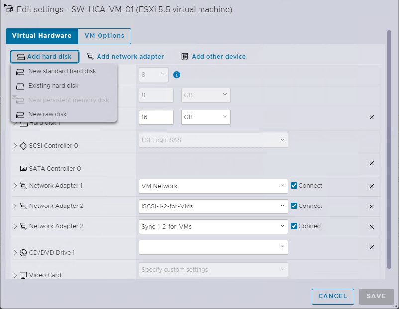
1. Add the new standard hard disk to StarWind VM from the existing datastore:
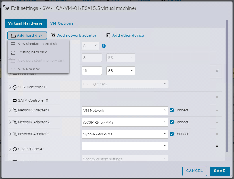
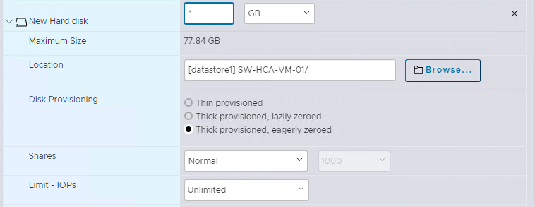
2. Specify the size and type of the new hard disk.
The type of Disk Provisioning should be Thick Provision Eager Zeroed
3. Modify the StarWind VM file to resolve the issue with ESXI: VMware Knowledge Base
Edit and save the VMX file of the StarWind VM by adding the following lines:
scsi0.async = “FALSE”
scsi0:0.canBlock = “TRUE”
scsi0:1.canBlock = “TRUE”
Line 1 shall be introduced for every SCSI controller your VM has got (0, 1, or whatever its number is). Line 2 shall be introduced for every port on that controller (here is why we use line 3 – just for example purposes in case of two disks attached to the VM using 1 SCSI controller).
In this example, VM got one SCSI adapter and two disks assigned to it.
RDM
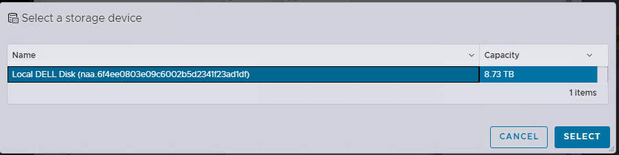
1. Add the new raw disk to StarWind VM.
2. Select the RAID array for StarWind devices
PCI
1. Open ESXI web → Manage → Hardware → PCI Devices. Find the RAID Controller or HBA disks.

2. Toggle passthrough for the RAID Controller or HBA disks, and refresh a page.
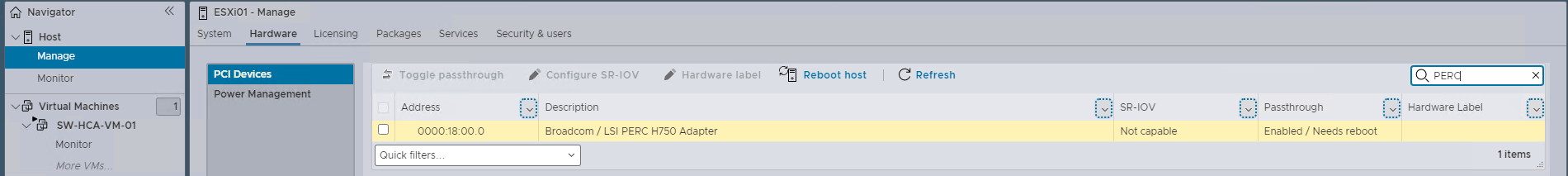
3. Reboot the ESXi server.
4. Add PCI devices to StarWind VM.

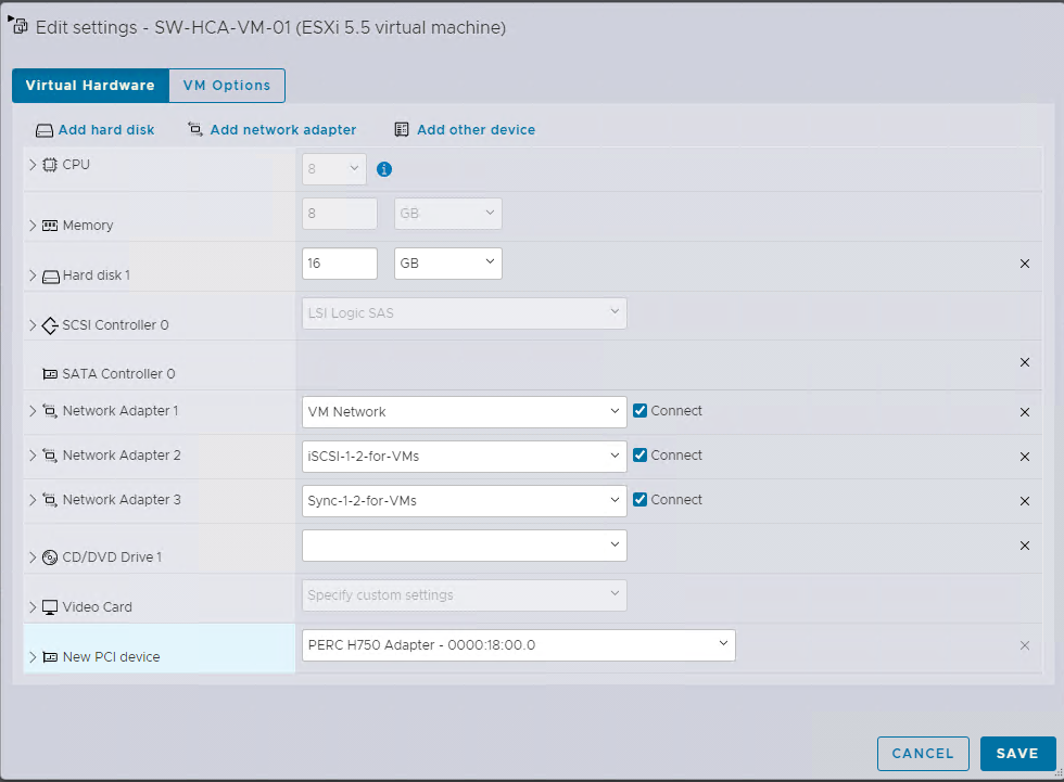
5. Save the configuration.
StarWind Configuration Part
To manage StarWind service you need to download and install StarWind Management Console.
1. Install StarWind Management Console on a workstation with Windows OS (Windows 7 or higher, Windows Server 2008 R2 and higher) using the installer available here.
NOTE: StarWind Management Console and PowerShell Management Library components are required.
2. Select the appropriate option to apply the StarWind License key.
Once the appropriate license key has been received, it should be applied to StarWind Virtual SAN service via Management Console or PowerShell.
3. Open StarWind Management Console and click Add Server.
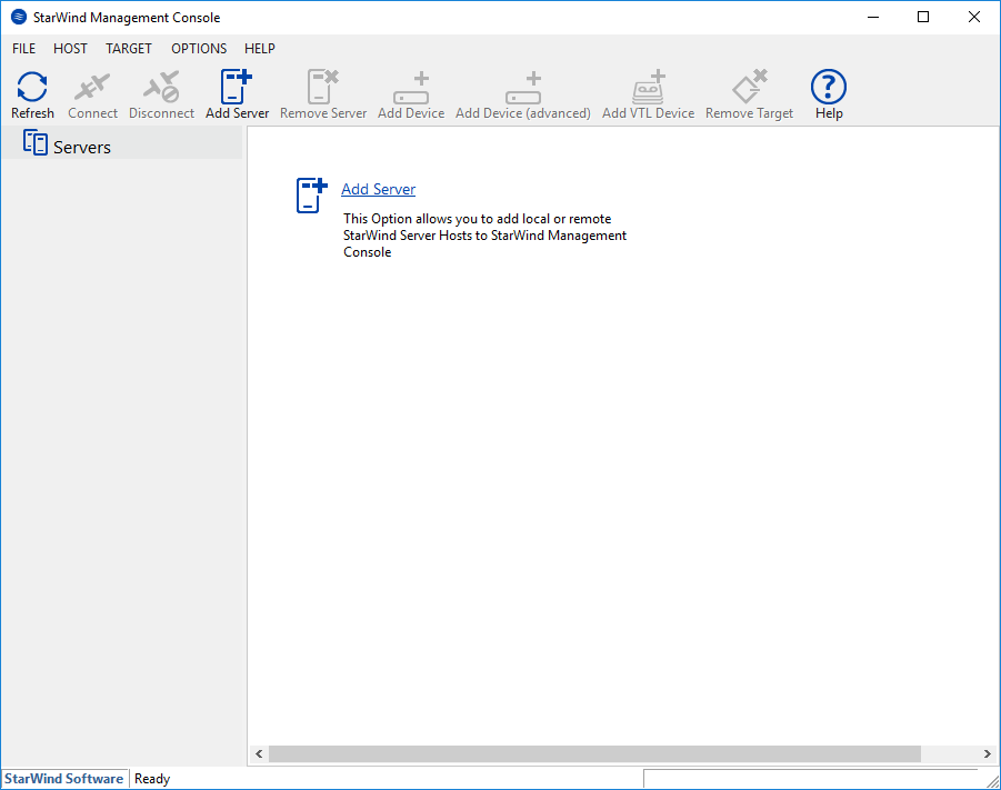
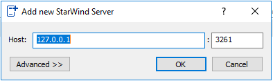
4. Type the IP address of the StarWind Virtual SAN in the pop-up window and click OK.
5. Select the server and click Connect.

6. Click Apply Key… on the pop-up window.
7. Select Load license from the file and click the Load button.
8. Select the appropriate license key.
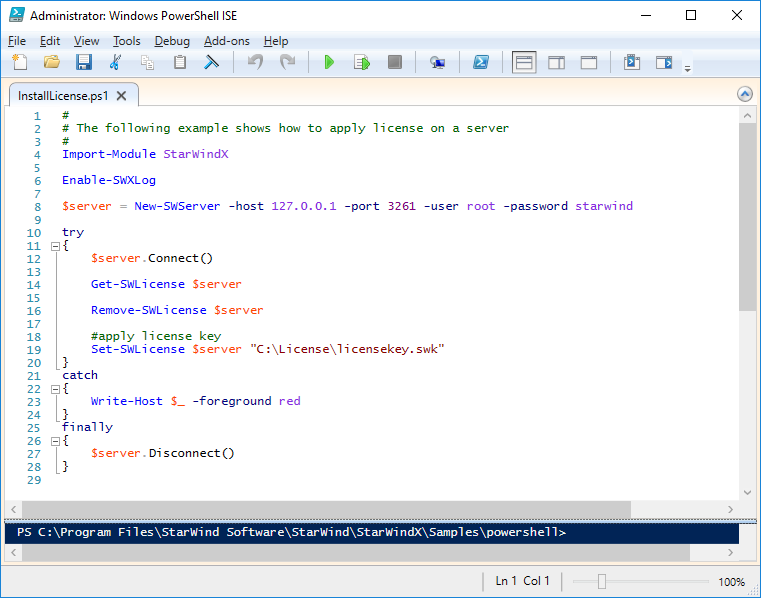
As an alternative, PowerShell can be used. Open StarWind InstallLicense.ps1 script with PowerShell ISE as administrator. It can be found here:
C:\Program Files\StarWind Software\StarWind\StarWindX\Samples\powershell\InstallLicense.ps1
Type the IP address of StarWind Virtual SAN VM and credentials of StarWind Virtual SAN service (defaults
login: root, password: starwind).
Add the path to the license key.
9. After the license key is applied, StarWind devices can be created.
NOTE: In order to manage StarWind Virtual SAN service (e.g. create ImageFile devices, VTL devices, etc.), StarWind Management Console can be used.
Configure StarWind VM
Names:
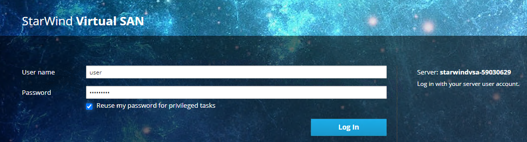
1. To log in to the StarWind VSAN VM web console you need to type the VM IP address and port 9090
Example: 192.168.1.1:9090
The default credentials:
Login: user
Password: rds123RDS

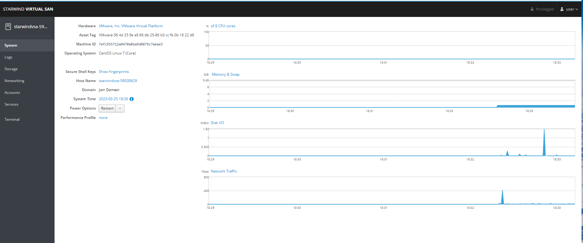
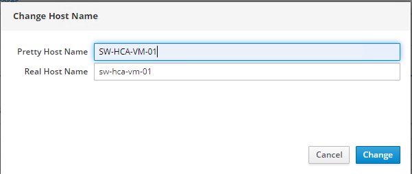
2. On the “System” page click on the “Host Name” and change it according to the default StarWind names or a specific name.
Networks:
1. To log in to the StarWind VSAN VM web console you need to type the VM IP address and port 9090
Example: 192.168.1.1:9090
The default credentials:
Login: user
Password: rds123RDS

2. On the “Networking” page click on the “ens192” to set the management IP-address.
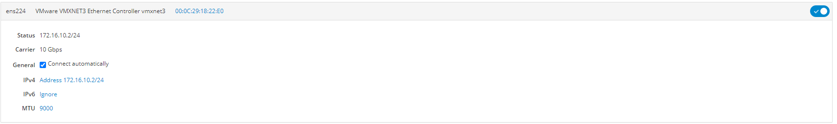
”ens224” – is for iSCSI and should have the following IP-address 172.16.10*/24
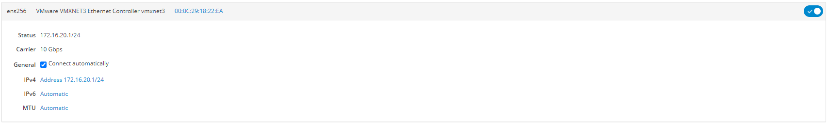
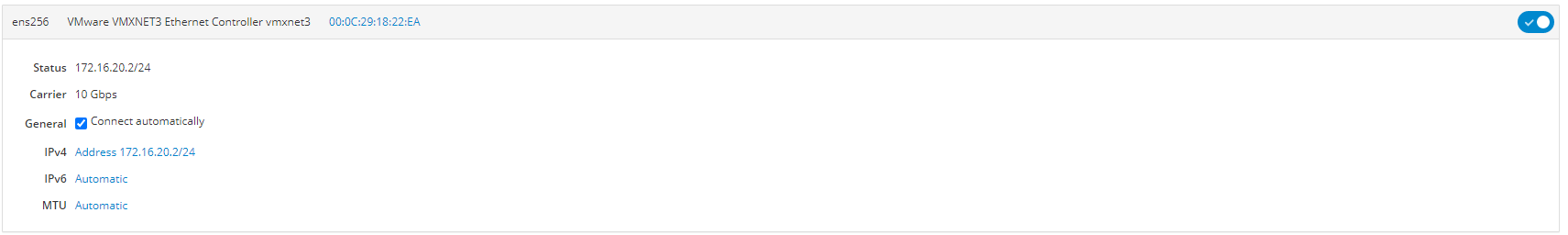
”ens256” – is for Synchronization and should have following IP-address 172.16.20*/24
3. iSCSI and Synchronization networks should have the following settings:
Node 1:
iSCSI 172.16.10.1/24
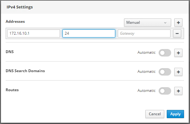
IPv6 should be disabled and MTU set to 9000.

Synchronization 172.16.20.1/24

IPv6 should be disabled and MTU set to 9000.
Node 2:
iSCSI 172.16.10.2/24
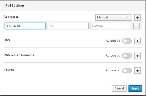
IPv6 should be disabled and MTU set to 9000.
Synchronization 172.16.20.2/24

IPv6 should be disabled and MTU set to 9000.
Storage:
Single disk based on hardware:
1. Login to StarWind VSAN VM web console and find in the Storage section under Drives the Disk that was recently added and choose it.
Note: To log in to the StarWind VSAN VM web console you need to type the VM IP address and port 9090
Example: 192.168.1.1:9090
The default credentials:
Login: user
Password: rds123RDS
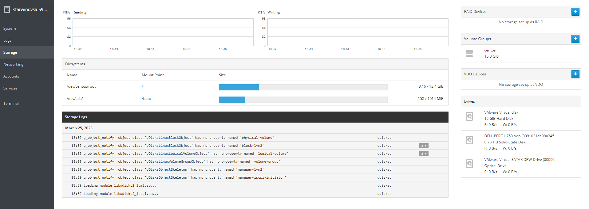
2. The added disk does not have any partitions and filesystem.
Press on Create Partition Table button to create the partition and format it.
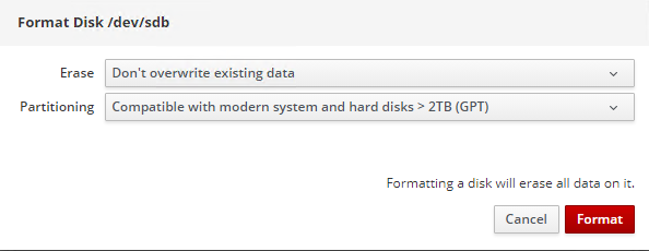
Press on Format button to create the partition and format it.
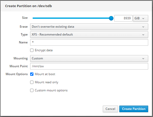
3. Press on Create Partition button to create the partition and format it.
Create the XFS partition. Specify the name and erase option. The mount point should be as following: /mnt/sw . Click Create Partition.
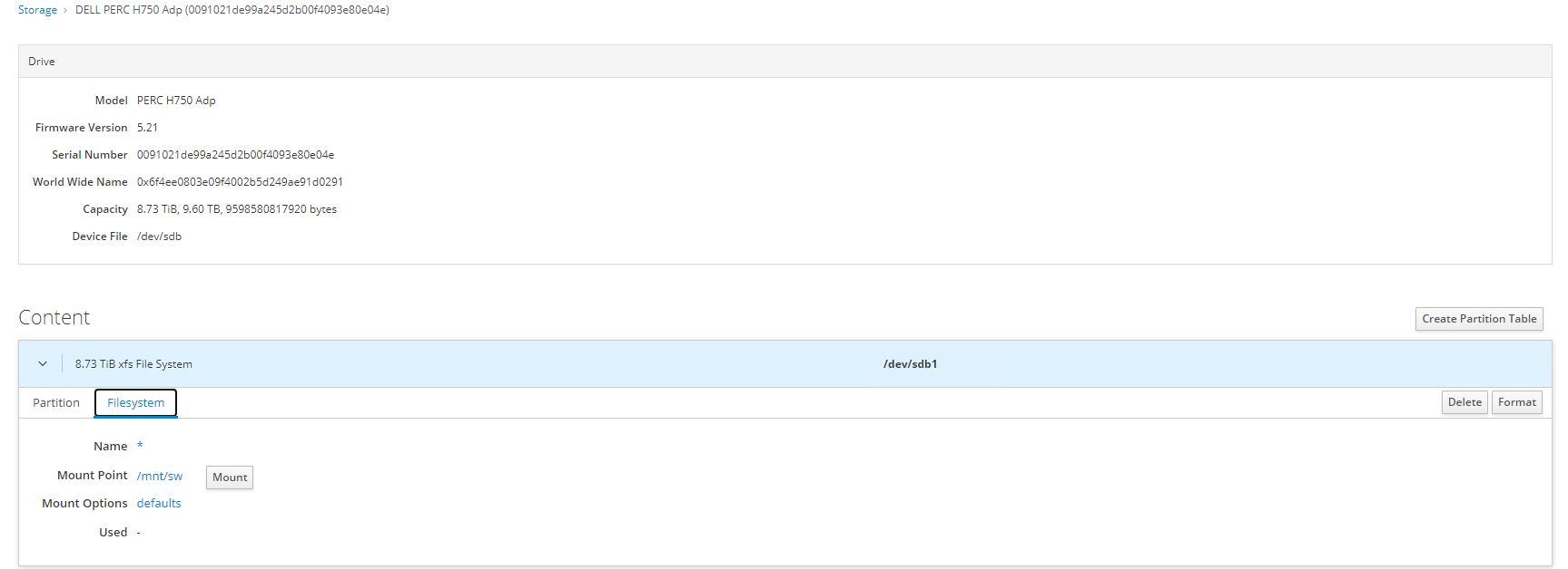
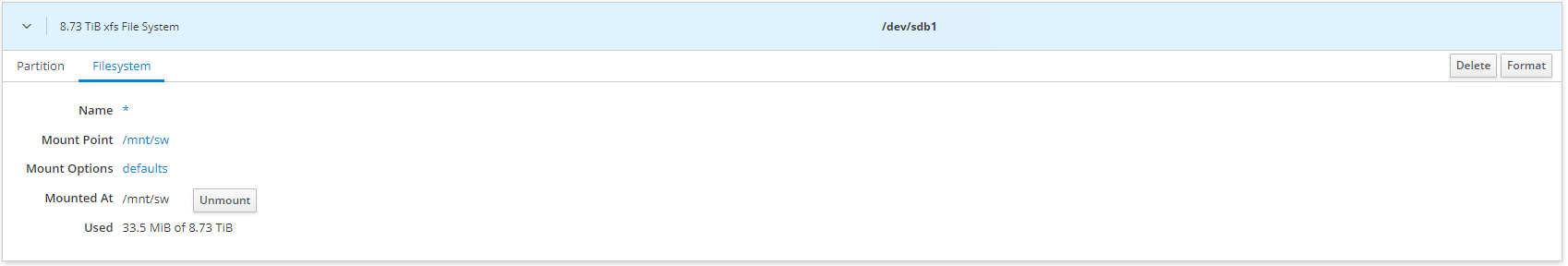
4. On the storage page of the disk, navigate to the Filesystem tab. Click Mount.
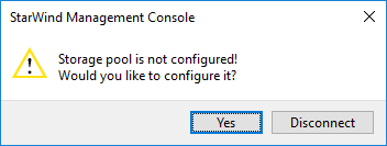
5. Connect to StarWind Virtual SAN from the StarWind Management Console. Click Yes.

6. Select the disk which was recently mounted.

Several disks for Software RAID:
1. Login to StarWind VSAN VM web console and find in the Storage section under Drives the Virtual Disk that was recently added and choose it.
Note: To log in to the StarWind VSAN VM web console you need to type the VM IP address and port 9090
Example: 192.168.1.1:9090
The default credentials:
Login: user
Password: rds123RDS

2. Go to the Storage page. The Drives section shows the drives connected to HBA/RAID Controller (if available).
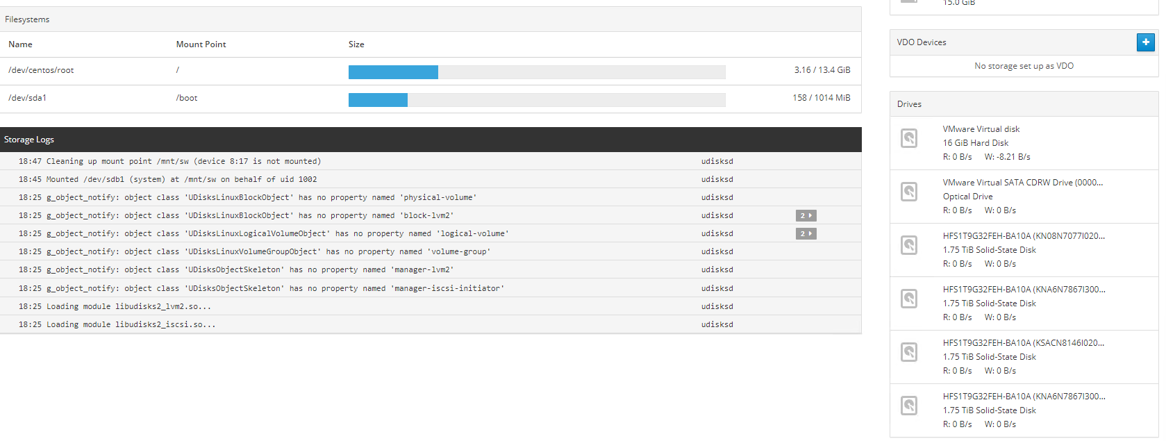
3. Click “+” in the RAID Devices section to create Software RAID. (In the current example, RAID 10 will be created with 4 HDD drives). StarWind recommendations of RAID configurations depending on the number of disks, chunk size, and array level are shown in the table below:
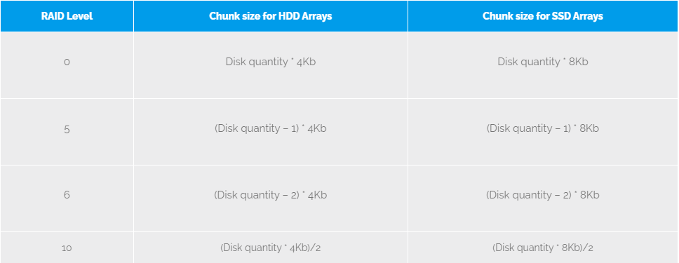
StarWind Software RAID recommended settings can be found here:
Recommended RAID settings for HDD and SSD disks – StarWind Knowledge Base
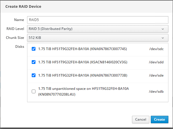
4. Select the drives to add to the array.
5. After the synchronization is finished, find the RAID array created.
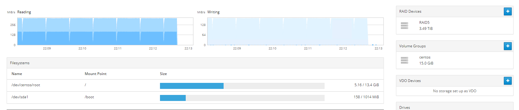
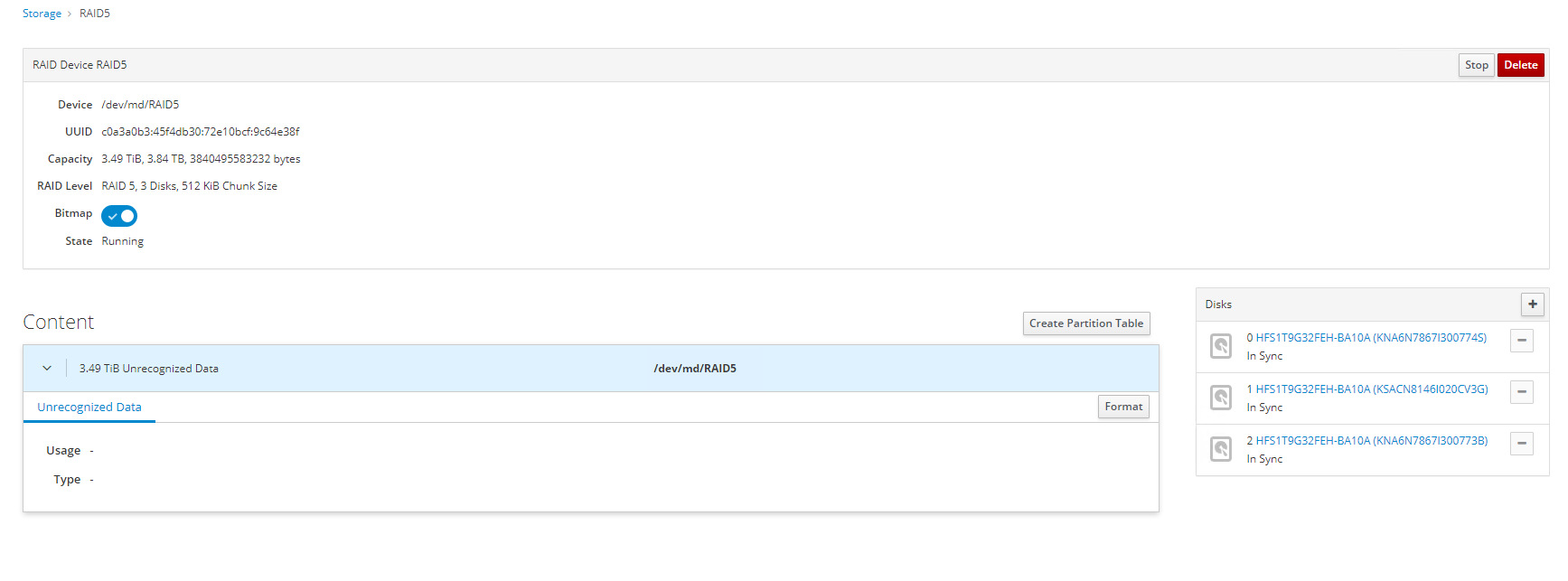
NOTE: The disk created will not have any partitions and file system. Click Format.
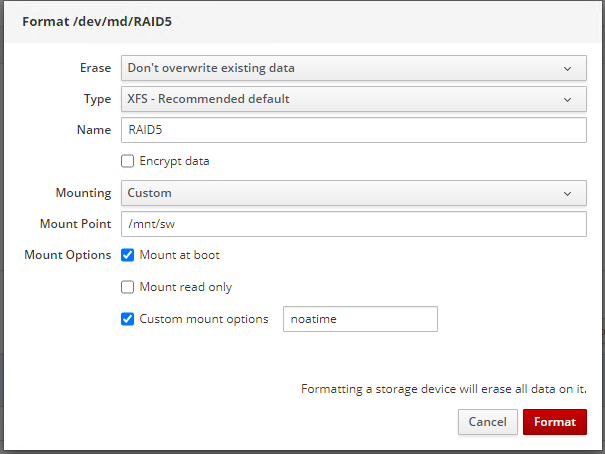
6. Create the XFS partition. Mount point should be as follows: /mnt/sw. Select the Custom mounting option and type noatime. Click Format.
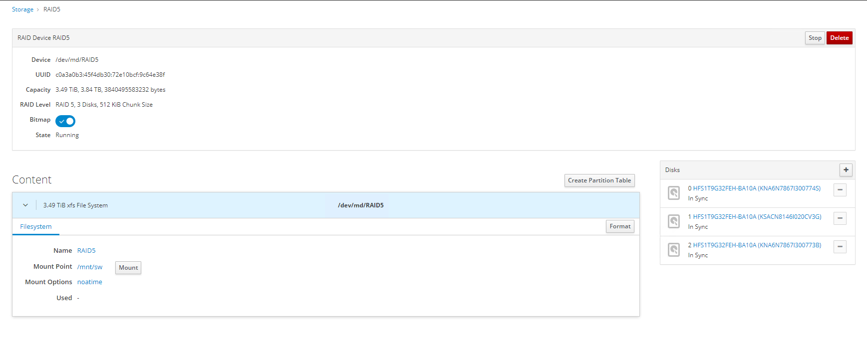
7. On the storage page of the disk, navigate to the Filesystem tab. Click Mount.
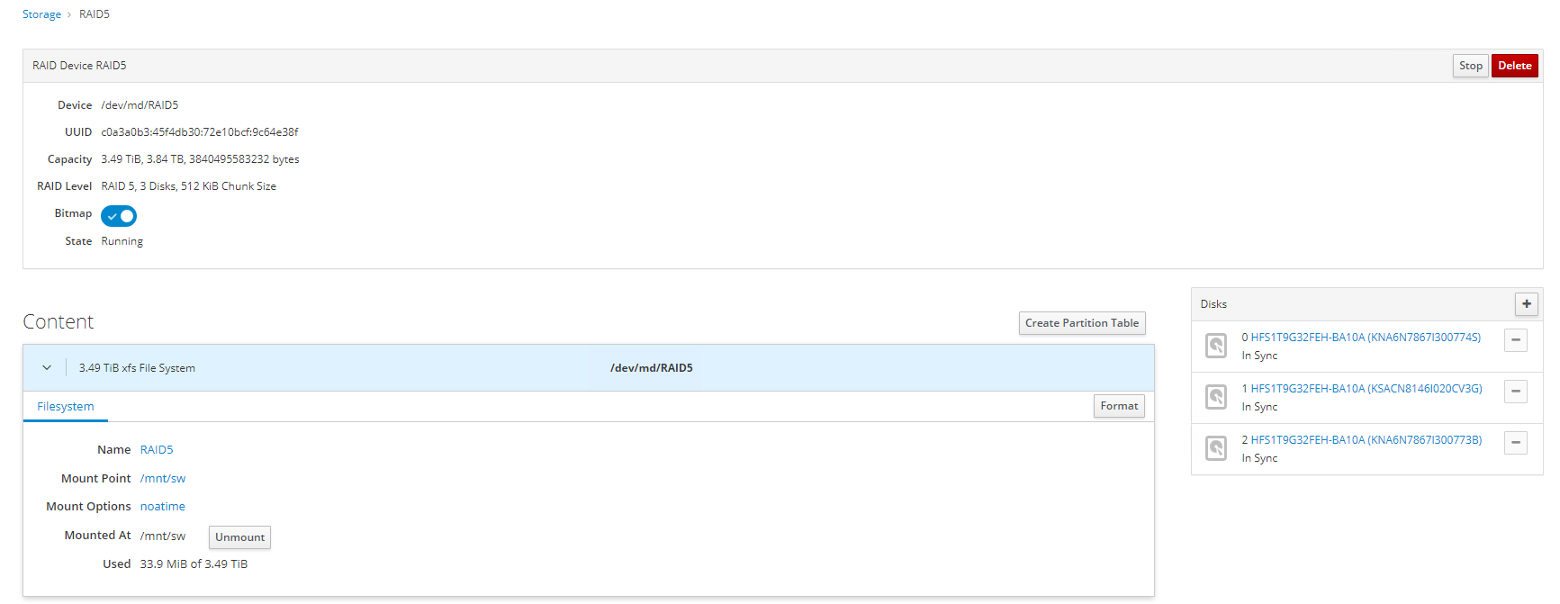
8. Connect to StarWind Virtual SAN from StarWind Management Console or from Web Console. Click Yes.
9. Select the disk recently mounted.

StarWind devices creation
For VMware the default number of StarWind devices is two DS1 and DS2.
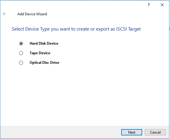
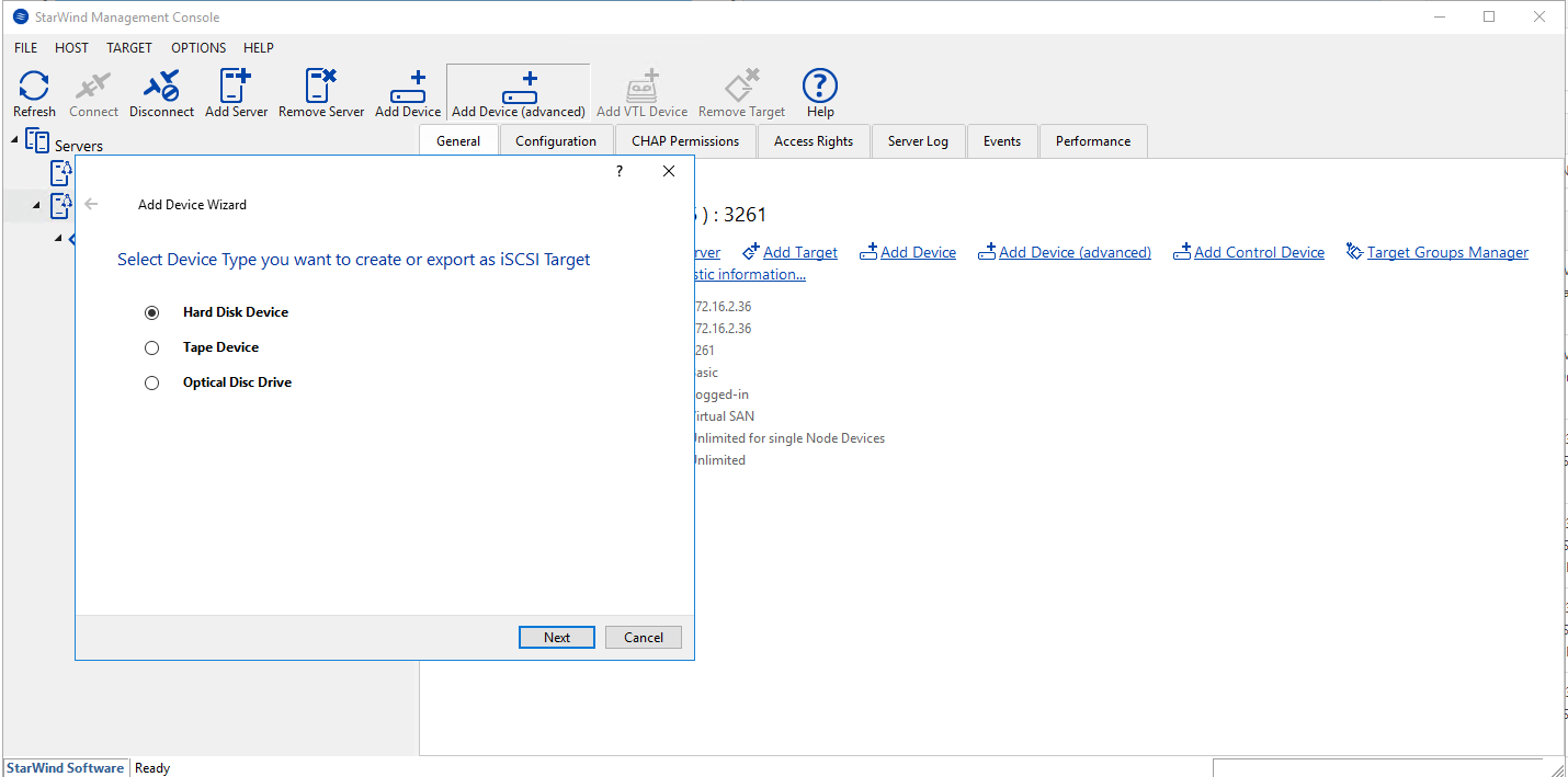
1. In the StarWind Management Console click on to Add Device (advanced) button and open Add Device (advanced) Wizard.
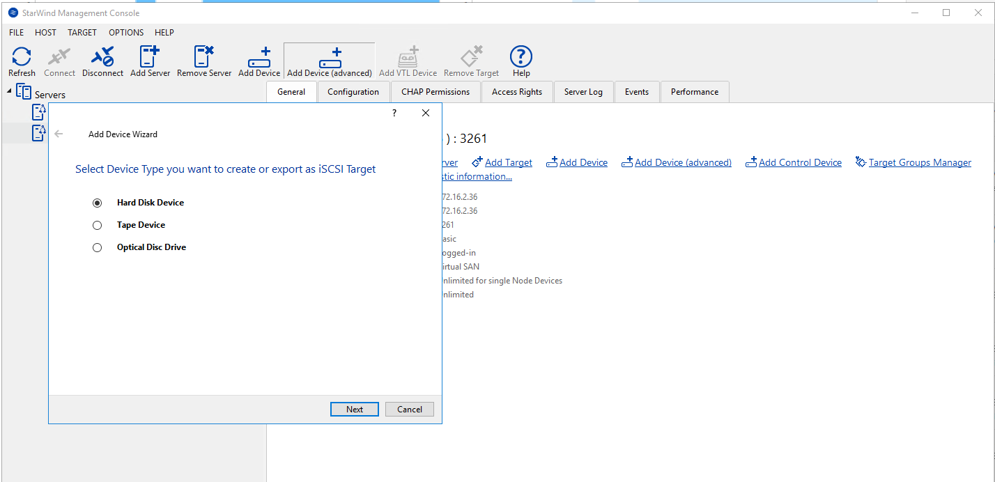
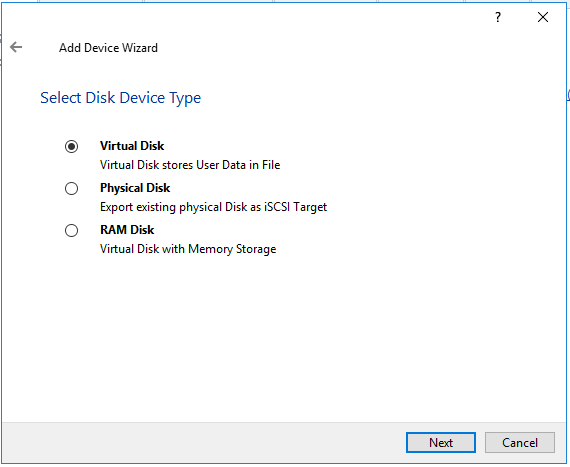
2. Select Hard Disk Device as the type of device to be created.
3. Select Virtual Disk.

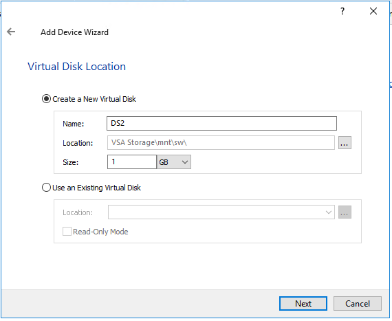
4. Specify a virtual disk Name, Location, and Size.
The size should be 1GB to do a quick synchronization.

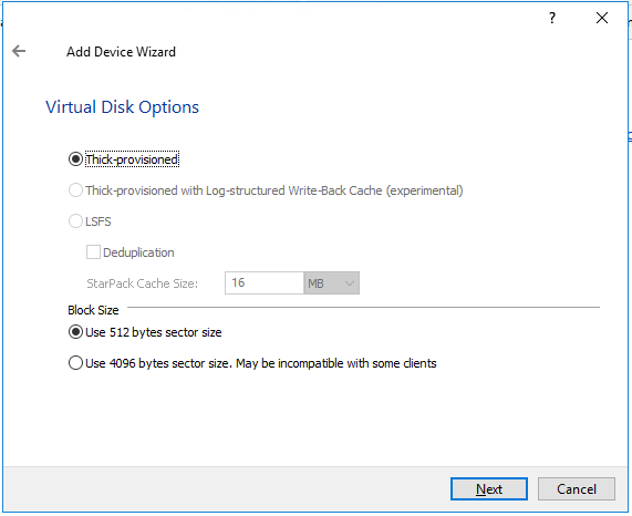
5. Select the Thick provisioned disk type and block size.
NOTE: Use 4096 sector size for targets, connected on Windows-based systems and 512 bytes sector size for targets, connected on Linux-based systems (ESXi/Xen/KVM).
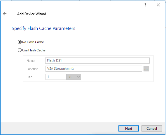
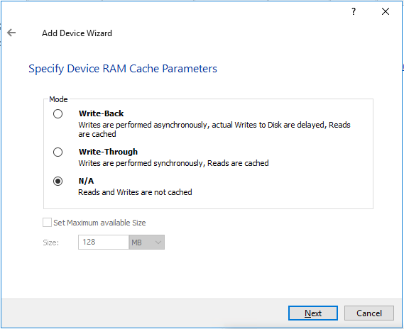
6. Define a caching policy and specify a cache size (in MB). Also, the maximum available cache size can be specified by selecting the appropriate checkbox. Optionally, define the L2 caching policy and cache size.

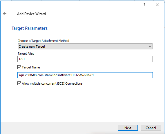
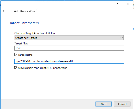
7. Specify Target Parameters. Select the Target Name checkbox to enter a custom target name. Otherwise, the name is generated automatically in accordance with the specified target alias.
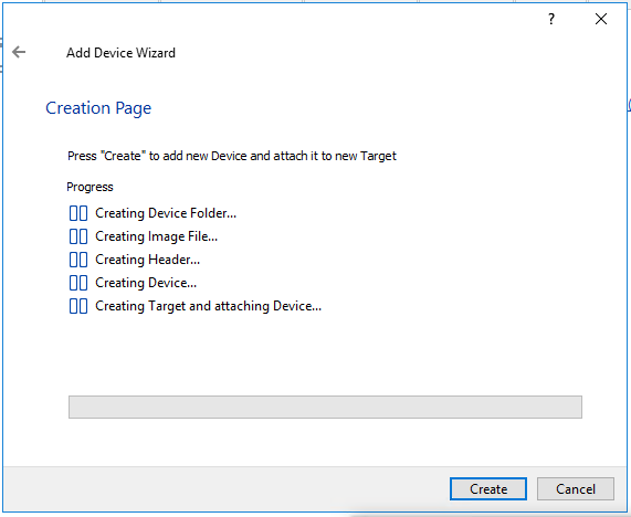
8. Click Create to add a new device and attach it to the target.

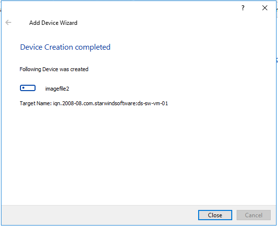
9. Click Close to finish the device creation.
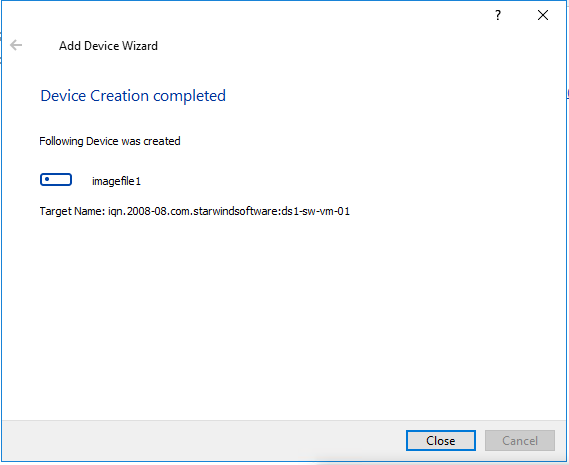
10. The successfully added devices appear in the StarWind Management Console.

11. Click on to Add Device (advanced) button and open Add Device (advanced) Wizard.
12. Select Hard Disk Device as the type of device to be created.

13. Select Virtual Disk.
14. Specify a virtual disk Name, Location, and Size.
The size should be 1GB to do a quick synchronization.
15. Select the Thick provisioned disk type and block size.
NOTE: Use 4096 sector size for targets, connected on Windows-based systems and 512 bytes sector size for targets, connected on Linux-based systems (ESXi/Xen/KVM).

16. Define a caching policy and specify a cache size (in MB). Also, the maximum available cache size can be specified by selecting the appropriate checkbox. Optionally, define the L2 caching policy and cache size.

17. Specify Target Parameters. Select the Target Name checkbox to enter a custom target name. Otherwise, the name is generated automatically in accordance with the specified target alias.
18. Click Create to add a new device and attach it to the target.
19. Click Close to finish the device creation.
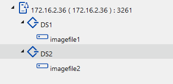
20. The successfully added devices appear in the StarWind Management Console.
StarWind replication of devices
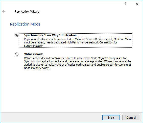
The replication should be configured using Synchronous “Two-Way” Replication mode:
Synchronous or active-active replication ensures real-time synchronization and load balancing of data between two or three cluster nodes. Such a configuration tolerates the failure of two out of three storage nodes and enables the creation of an effective business continuity plan. With synchronous mirroring, each write operation requires control confirmation from both storage nodes. It guarantees the reliability of data transfers but is demanding in bandwidth since mirroring will not work on high-latency networks.
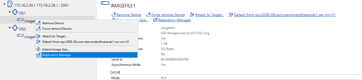
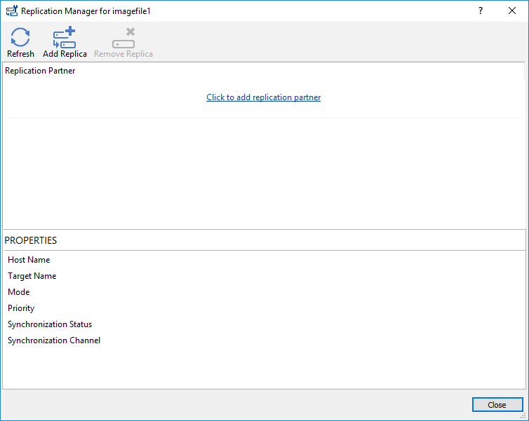
1. Right-click on the DS1 device and select Replication Manager from the shortcut menu.
2. Select the Add Replica button in the top menu.
3. Select Synchronous “Two-Way” replication as a replication mode.

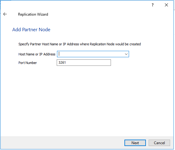
4. Specify a partner Host name or IP address and Port Number.

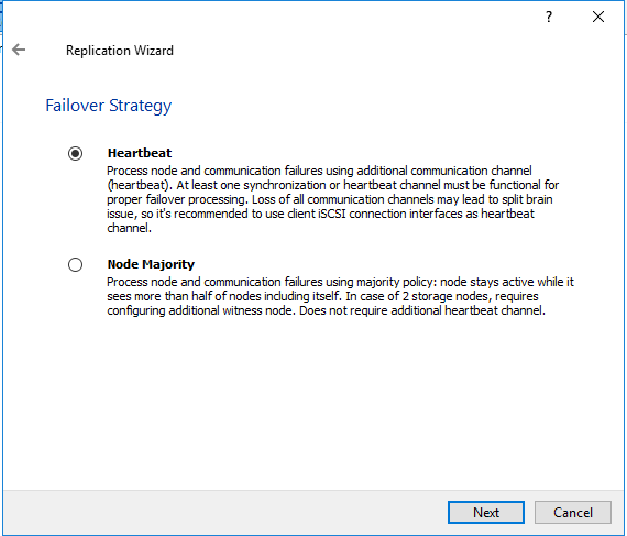
5. Select Failover Strategy.

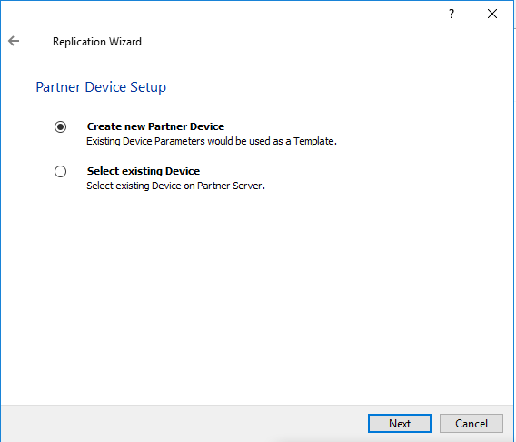
6. Select Create new Partner Device and click Next.

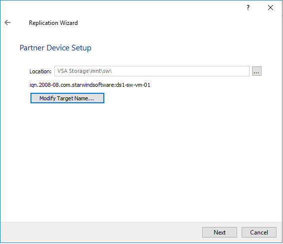
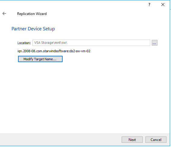
7. Select a partner device Location and click Next.
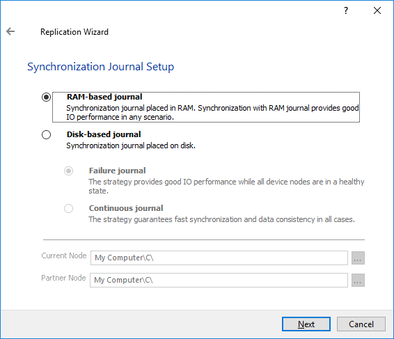
8. Select Synchronization Journal Strategy and click Next.
NOTE: There are several options – RAM-based journal (default) and Disk-based journal with failure and continuous strategy, that allow to avoid full synchronization cases.
RAM-based (default) synchronization journal is placed in RAM. Synchronization with RAM journal provides good I/O performance in any scenario. Full synchronization could occur in the cases described in this KB: Reasons why Full Synchronization may start – StarWind Knowledge Base
Disk-based journal placed on a separate disk from StarWind devices. It allows to avoid full synchronization for the devices where it’s configured even when StarWind service is being stopped on all nodes.
Disk-based synchronization journal should be placed on a separate, preferably faster disk from StarWind devices. SSDs and NVMe disks are recommended as the device performance is defined by the disk speed, where the journal is located. For example, it can be placed on the OS boot volume.
It is required to allocate 2 MB of disk space for the synchronization journal per 1 TB of HA device size with a disk-based journal configured and 2-way replication and 4MB per 1 TB of HA device size for 3-way replication.
Failure journal – provides good I/O performance, as a RAM-based journal, while all device nodes are in a healthy synchronized state. If a device on one node went into a not synchronized state, the disk-based journal activates and a performance drop could occur as the device performance is defined by the disk speed, where the journal is located. Fast synchronization is not guaranteed in all cases. For example, if a simultaneous hard reset of all nodes occurs, full synchronization will occur.
Continuous journal – guarantees fast synchronization and data consistency in all cases. Although, this strategy has the worst I/O performance, because of frequent write operations to the journal, located on the disk, where the journal is located.
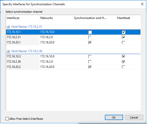
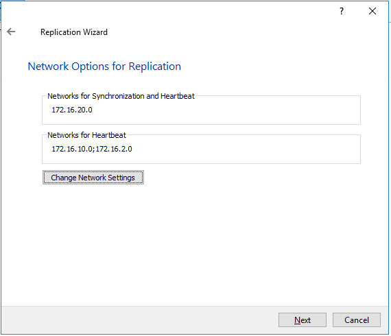
9. Click Change Network Settings.

10. Specify the interfaces for Synchronization and Heartbeat Channels. Click OK and then click Next.
172.16.20.* -Synchronization
172.16.10.* and Management as HeartBeat
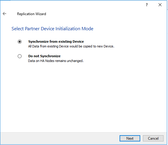
11. In Select Partner Device Initialization Mode, select Synchronize from existing Device and click Next.

12. Click Create Replica.

13. Click Close to close the wizard.
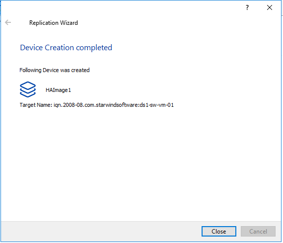

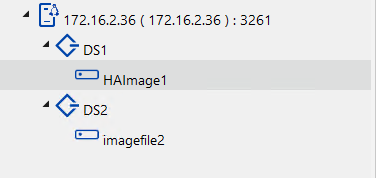
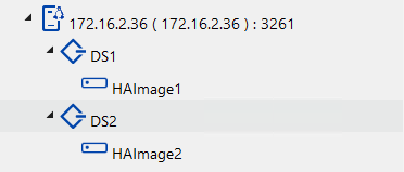
14. The successfully added device appears in StarWind Management Console.
15. Right-click on the DS2 device and select Replication Manager from the shortcut menu.
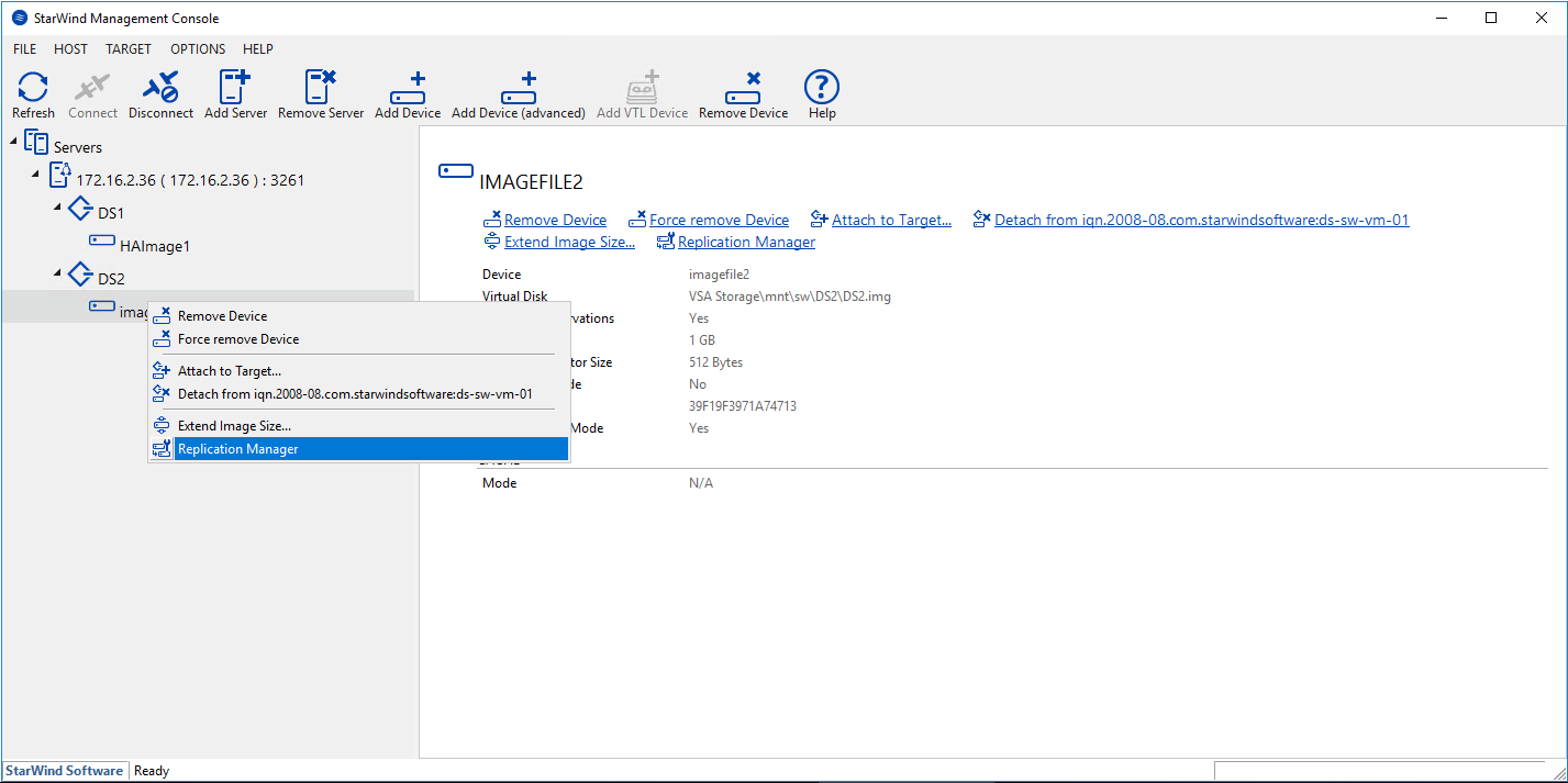
16. Select the Add Replica button in the top menu.

17. Select Synchronous “Two-Way” replication as a replication mode.
18. Specify a partner Host name or IP address and Port Number.
19. Select Failover Strategy.
20. Select Create new Partner Device and click Next.
21. Select a partner device Location and click Next.
22. Select Synchronization Journal Strategy and click Next.
NOTE: There are several options – RAM-based journal (default) and Disk-based journal with failure and continuous strategy, that allow to avoid full synchronization cases.
RAM-based (default) synchronization journal is placed in RAM. Synchronization with RAM journal provides good I/O performance in any scenario. Full synchronization could occur in the cases described in this KB: Reasons why Full Synchronization may start – StarWind Knowledge Base
Disk-based journal placed on a separate disk from StarWind devices. It allows to avoid full synchronization for the devices where it’s configured even when StarWind service is being stopped on all nodes.
Disk-based synchronization journal should be placed on a separate, preferably faster disk from StarWind devices. SSDs and NVMe disks are recommended as the device performance is defined by the disk speed, where the journal is located. For example, it can be placed on the OS boot volume.
It is required to allocate 2 MB of disk space for the synchronization journal per 1 TB of HA device size with a disk-based journal configured and 2-way replication and 4MB per 1 TB of HA device size for 3-way replication.
Failure journal – provides good I/O performance, as a RAM-based journal, while all device nodes are in a healthy synchronized state. If a device on one node went into a not synchronized state, the disk-based journal activates and a performance drop could occur as the device performance is defined by the disk speed, where the journal is located. Fast synchronization is not guaranteed in all cases. For example, if a simultaneous hard reset of all nodes occurs, full synchronization will occur.
Continuous journal – guarantees fast synchronization and data consistency in all cases. Although, this strategy has the worst I/O performance, because of frequent write operations to the journal, located on the disk, where the journal is located.

23. Click Change Network Settings.
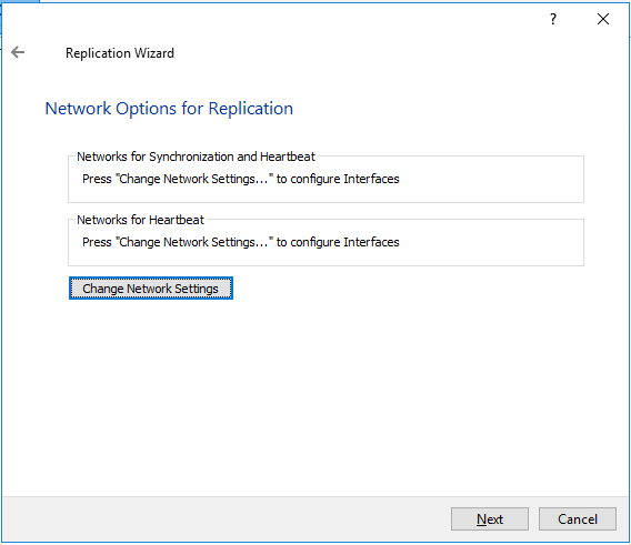
24. Specify the interfaces for Synchronization and Heartbeat Channels. Click OK and then click Next.
172.16.20.* -Synchronization
172.16.10.* and Management as HeartBeat


25. In Select Partner Device Initialization Mode, select Synchronize from existing Device and click Next.
26. Click Create Replica.

27. Click Close to close the wizard.

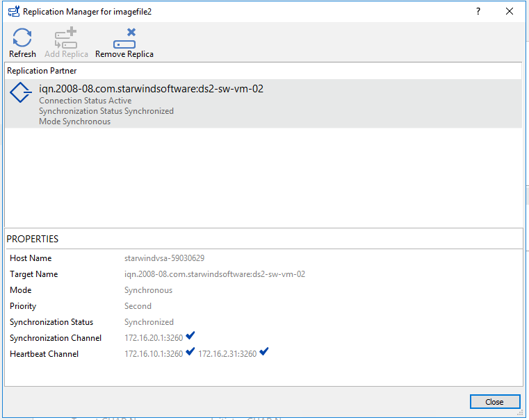
28. The successfully added device appears in StarWind Management Console.
Extend StarWind devices:
1. Right-click on the DS1 device and select (Extending Size of HA (High Availability Device) from the shortcut menu.
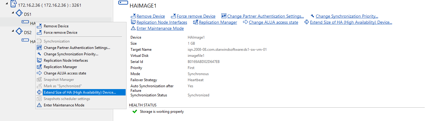
2. Enter the Amout of space to extend.
DS1 need to add 511GB
DS2 need to add 1023GB
Datastore creation on top of StarWind devices
1. Open the Storage tab on one of ESXi hosts and click on New Datastore.
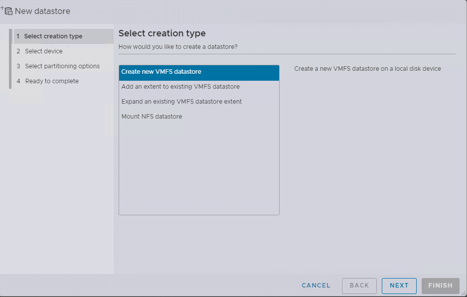
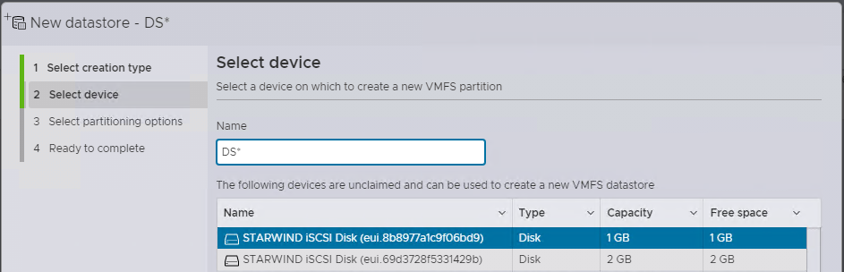
2. Specify the Datastore name, select the previously discovered StarWind device, and click Next.
3. Enter the datastore size and click Next.

4. Verify the settings and click Finish.

5. Add another Datastore (DS2) in the same way but select the second device for the second datastore.
6. Verify that your storages (DS1, DS2) are connected to both hosts. Otherwise, rescan the storage adapter.
NOTE: Path Selection Policy changing for Datastores from Most Recently Used (VMware) to Round Robin (VMware) is added into the Rescan Script, and this action is performed automatically.
Configuration of I/O Scheduler
1. Login to StarWind VSAN VM web console and find in the Storage section under Drives the Virtual Disk that was recently added and choose it.
Note: To log in to the StarWind VSAN VM web console you need to type the VM IP address and port 9090
Example: 192.168.1.1:9090
The default credentials:
Login: user
Password: rds123RDS

2. Open the “Terminal” page.
3. Check the storage to identify the disks,
type lsblk.

4. Checking the scheduler settings:
type cat /sys/block/sd*/queue/scheduler.
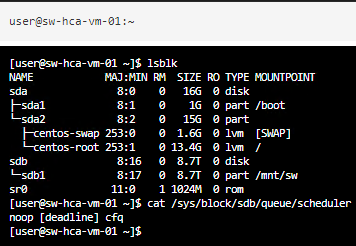
Result: [ [bfq] mq-deadline none ] OR [ noop deadline [cfq] ]
5. Set the scheduler settings:
type sudo nano /etc/udev/rules.d/89-disk-scheduler.rules.
![]()
Password: rds123RDS
#Set none scheduler for non-rotating disks
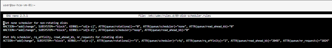
ACTION==”add|change”, SUBSYSTEM==”block”, KERNEL==”sd[b-d]“, ATTR{queue/scheduler}=”noop”, ATTR{queue/read_ahead_kb}=”0″
where sd[b-d] are disks settings that should be applied. For a single disk use sdb or sdc .
Note: For SSD disks scheduler should be “noop” , for HDD “cfq“
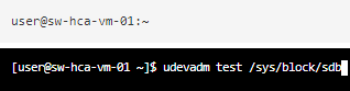
6. Check the rule:
type udevadm test /sys/block/sd*
7. Check settings:
type cat /sys/block/sd*/queue/scheduler
8. Do the above changes for all StarWind Virtual machines.
Configuring an Automatic Storage Rescan
1. Open the Terminal page.
2. Edit file /opt/StarWind/StarWindVSA/drive_c/StarWind/hba_rescan.ps1 with the following command:
sudo nano /opt/StarWind/StarWindVSA/drive_c/StarWind/hba_rescan.ps1
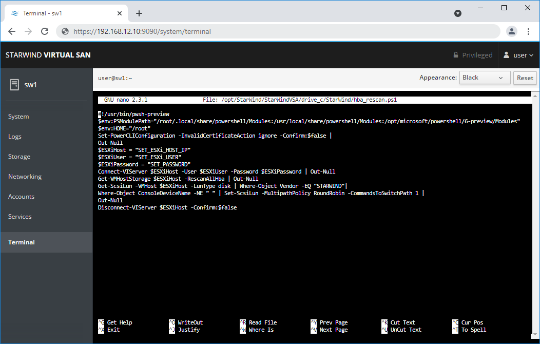
3. In the appropriate lines, specify the IP address and login credentials of the ESXi host (see NOTE below) on which the current StarWind VM is stored and running:
$ESXiHost = “IP address”
$ESXiUser = “Health”
$ESXiPassword = “StarWind2015!”
NOTE: In some cases the rescan script can be changed and storage rescan added for another ESXi host. Appropriate lines should be duplicated and changed with properly edited variables if required.
Make sure that rescan script is working and execute it from the VM:
sudo /opt/StarWind/StarWindVSA/drive_c/StarWind/hba_rescan.ps1
4. Repeat all steps from this section on the all other StarWind Virtual machines.
ProActive agent configuration
1. Stop the StarWindHealth
systemctl stop StarWindHealth.service
2. Change a line in /etc/systemd/system/StarWindHealth.service
ExecStart=/opt/StarWind/StarWindHealth/bin/nxagentd -d -c /etc/StarWindHealth.conf -M freepas.starwind.com
to
ExecStart=/opt/StarWind/StarWindHealth/bin/nxagentd -d -c /etc/StarWindHealth.conf -M pas.starwind.com
3. Reload the configuration for systemd
systemctl daemon-reload
4. Start the StarWindHealth
systemctl start StarWindHealth
5. Repeat all steps from this section on the all other StarWind Virtual machines.
Conclusion
Following this guide, a StarWind Virtual HCI Appliance (VHCA) powered by VMware vSphere was deployed and configured with StarWind Virtual SAN (VSAN) running in a CVM on each host. As a result, a virtual shared storage “pool” accessible by all cluster nodes was created for storing highly available virtual machines.
