

Creating Highly Available device using Node Majority Failover Strategy
- March 20, 2018
- 15 min read
INTRODUCTION
When the connection between nodes with synchronous replication is lost, it is important to decide which nodes should continue to serve client’s requests, and which ones should disconnect and stop working with the client. The loss of communication can occur either due to problems with the link between the nodes or due to problems with a node itself.
In case communication loss is caused by network connection problems between HA nodes, there is a danger of the “split brain” state in the HA device. This situation is possible if both nodes lose all synchronization and heartbeat connections between them simultaneously and are unable to communicate anymore to define the synchronization state of each other. Each node decides that it is the only synchronized and operational one, and thus continues to proceed clients’ requests for read and write operations independently. When the synchronization link finally is restored, differences in data written to the disk on each node will lead to data corruption, as different information is attempted to get synchronized. To avoid this, users can choose the failover strategy when creating an HA device. The available options are heartbeat and node majority failover strategies.
This guide is intended for server administrators. It provides detailed instructions on how to set up an HA device using the Node Majority Failover strategy with the Witness Node based on StarWind Virtual SAN as a storage provider.
A full set of up-to-date technical documentation can always be found here.
For any technical inquiries, please, visit our online community, Frequently Asked Questions page, or use the support form to contact our technical support department.
StarWind Failover Strategies
Selection of the failover strategy is done during the device creation and cannot be changed afterward. StarWind Virtual SAN provides two options: Heartbeat failover strategy and Node Majority failover strategy.
Heartbeat Failover Strategy
Heartbeat is a technology that allows avoiding the so-called “split-brain” scenario when the HA cluster nodes are unable to synchronize but continue to accept writ commands from the initiators independently. It can occur when all synchronization and heartbeat channels disconnect simultaneously, and the partner nodes do not respond to the node’s requests. As a result, StarWind service assumes the partner nodes to be offline and continues operations on a single-node mode using data written to it.
If at least one heartbeat link is online, StarWind services can communicate with each other via this link. The device with the lowest priority will be marked as not synchronized and get subsequently blocked for the further read and write operations until the synchronization channel resumption. At the same time, the partner device on the synchronized node flushes data from the cache to the disk to preserve data integrity in case the node goes down unexpectedly. It is recommended to assign more independent heartbeat channels during replica creation to improve system stability and avoid the “split-brain” issue.
With heartbeat failover strategy, the storage cluster will continue working with only one StarWind node available.
You can find a configuration guide for creating HA storage with Heartbeat Failover Strategy here.
Node Majority Failover Strategy
This strategy ensures synchronization connection without any additional heartbeat links. The failure-handling process occurs when the node has detected the absence of connection with the partner.
The main requirement for keeping the node operational is an active connection with more than a half of the HA device’s nodes. Calculation of the available partners is based on their “votes”.
In case of a two-node HA storage, all nodes will be disconnected if there is a problem on the node itself, or in communication between them. Therefore, the Node Majority failover strategy does not work in case of just two synchronous nodes. To resolve this issue, it is necessary to add the third Witness node, which participates the nodes count for the majority, but neither contains data on it nor is involved in processing clients’ requests.
With Node Majority failover strategy, failure of only one node can be tolerated. If two nodes fail, the third one will also become unavailable to clients’ requests.
The Witness node should be additionally configured for an HA device that uses Node Majority failover strategy if it is replicated between 2 nodes. In case an HA device is replicated between 3 nodes, no Witness node is required.
Downloading, Installing, and Registering the Software
1. Download the StarWind setup executable file from our website by following the link:
https://www.starwind.com/registration-starwind-virtual-san
2. Launch the downloaded setup file on the server where you wish to install StarWind Virtual SAN or one of its components. The setup wizard will appear.
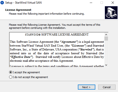
3. Read and accept the License Agreement and click Next to continue.
4. Carefully read the information about new features and improvements. Red text indicating warnings for users who update the existing software installations.
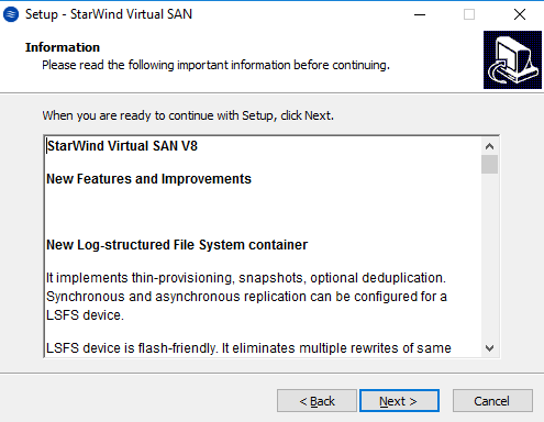
Click Next to continue.
5. Click Browse to modify the installation path if necessary.
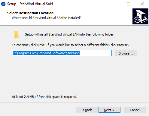
Click Next to continue.
6. Select the following components for the minimum setup:
- StarWind Virtual SAN Service
StarWind Service is the core of the software. It can create iSCSI targets and share virtual and physical devices. The service can be managed from StarWind Management Console on any Windows computer or VSA that is on the network. Alternatively, the service can be managed from StarWind Web Console, deployed separately. - StarWind Management Console
The Management Console is the Graphic User Interface (GUI) part of the software that controls and monitors all storage-related operations (e.g., allows users to create targets and devices on connected to the network StarWind Virtual SAN servers).
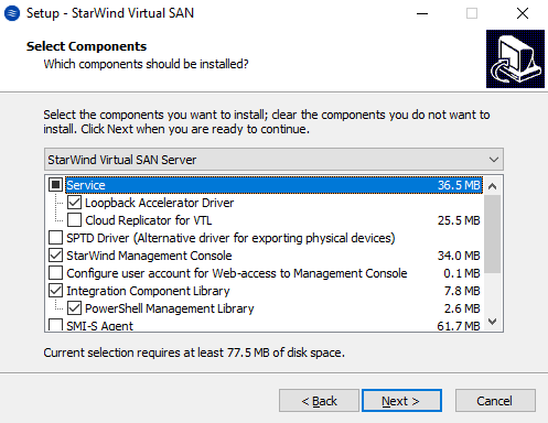
Click Next to continue.
7. Specify the Start Menu folder.
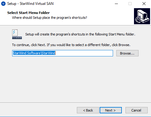
Click Next to continue.
8. Enable the checkbox if you want to create a desktop icon.
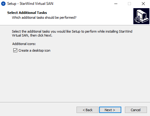
Click Next to continue.
9. You will be prompted to request a time-limited fully functional evaluation key, a FREE version key, or a fully commercial license key sent to you with the purchase of StarWind Virtual SAN. Select the appropriate option.
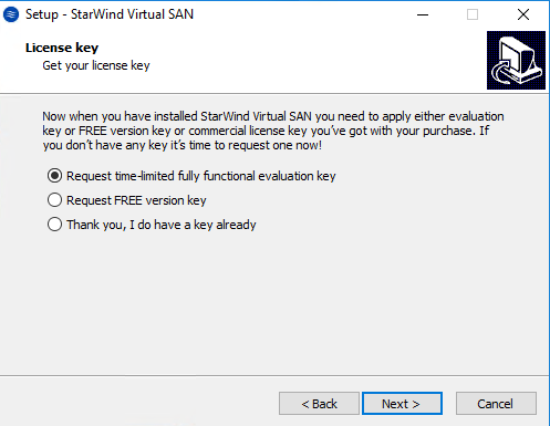
Click Next to continue.
10. Click Browse to locate the license file.
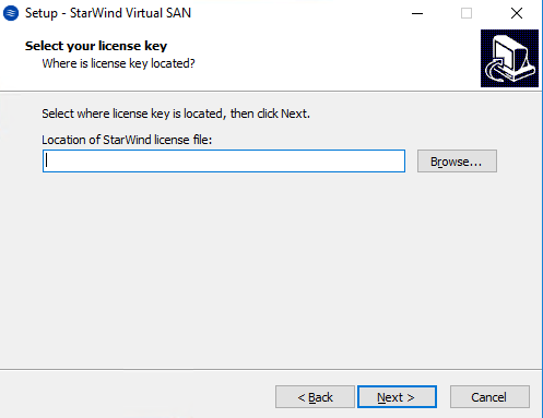
Click Next to continue.
11. Review the licensing information.
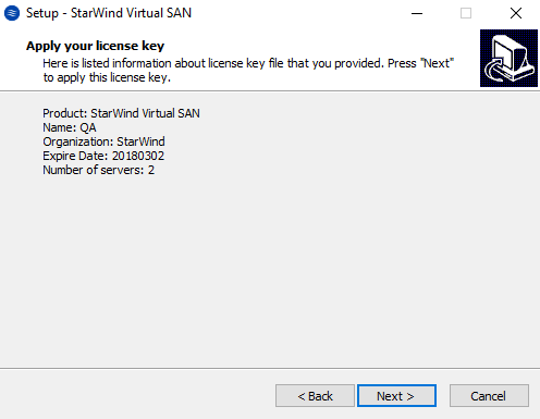
Click Next to apply the license key.
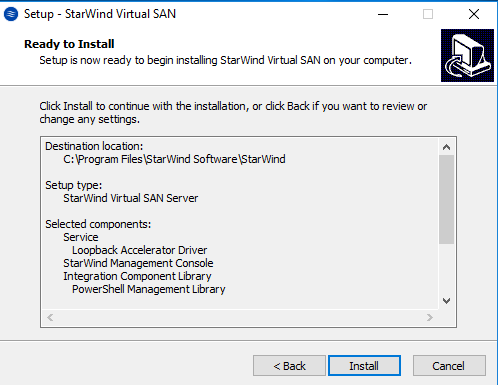
12. Verify the installation settings. Click Back to make any changes or Install to continue.
13. Select the appropriate checkbox to launch the StarWind Management Console immediately after the setup wizard is closed.
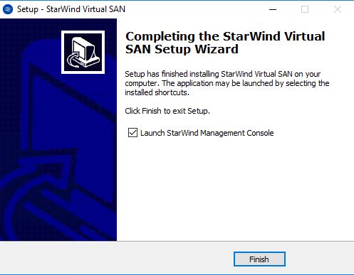
Click Finish to close the wizard.
14. Repeat installation steps on the other StarWind nodes, including the Witness node.
Configuring Shared Storage
NOTE: StarWind Management Console cannot be installed on an operating system without a GUI. You can install it on Windows Desktop 7, 8, 8.1, 10 and Windows Server 2008R2, 2012, 2012 R2, 2016 editions including the desktop versions of Windows.
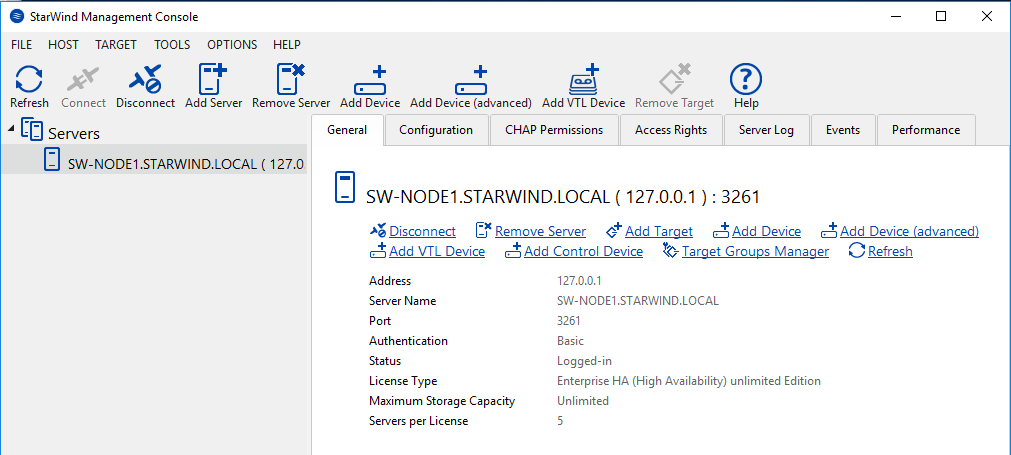
If StarWind Service and Management Console are installed on the same server, Management Console will automatically add the local StarWind node to the Console tree after the first launch. To add remote StarWind servers to the console, use the Add Server button on the control panel.
Launch the StarWind Management Console by double-clicking the StarWind tray icon.
15. StarWind Management console will ask you to specify the default storage pool on the server you are connecting to for the first time. Please configure the default storage pool to use one of the volumes you have prepared earlier. All the devices created through the Add Device wizard will be stored on it. Should you decide to use an alternative storage path for your StarWind virtual disks, please, use the Add Device (advanced) menu item to specify it.
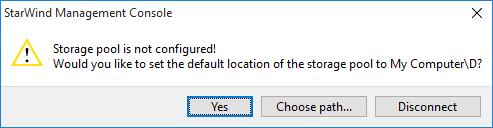
Press the Yes button to configure the storage pool. If you need to change the storage pool destination, press Choose path… and point the browser to the necessary disk.
NOTE: Each array used by StarWind Virtual SAN to store virtual disk images should meet the following requirements:
- initialized as GPT
- Have a single NTFS-formatted partition
- Have a drive letter assigned
16. Select the StarWind server where you wish to create the device.
17. Press the Add Device (advanced) button on the toolbar.
18. Add Device Wizard will appear. Select Hard Disk Device and click Next.
19. Select Virtual disk and click Next.
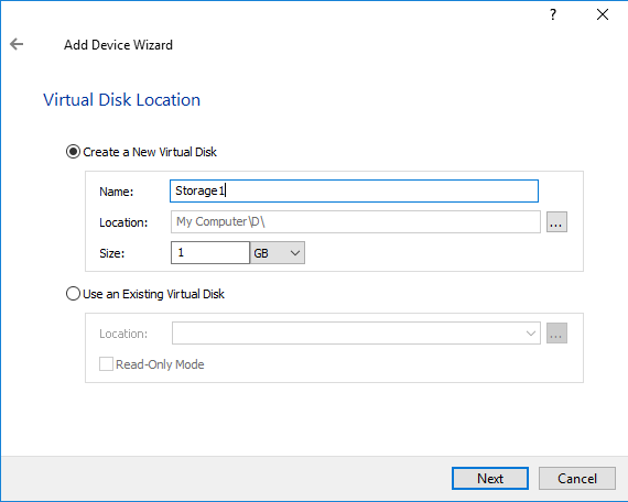
20. Specify the virtual disk location, the name, and the size and click Next.
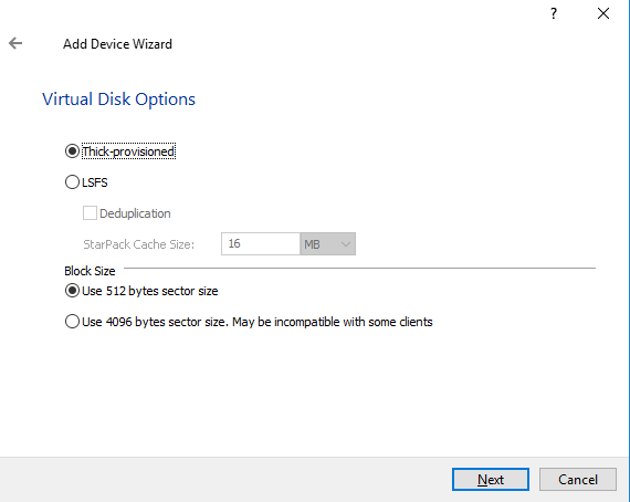
21. Choose the type of StarWind device, specify the virtual block size, and click Next
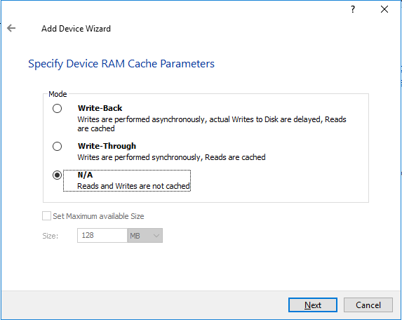
22. Define the caching policy and specify the cache size, if necessary, and click Next.
NOTE: It is recommended to assign 1 GB of the L1 cache in Write-Back or Write-Through mode per 1 TB storage capacity if necessary.
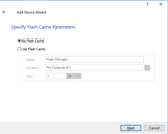
23. Define the Flash Cache Parameters policy and size if necessary. Choose an SSD location in the wizard. Click Next to continue.
NOTE: The recommended size of the L2 cache is 10% of the initial StarWind device capacity.
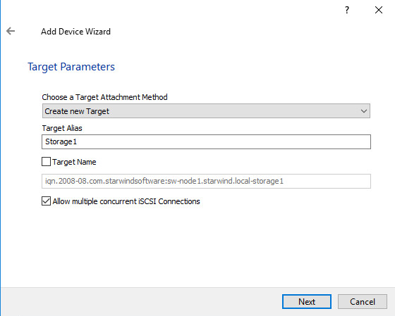
24. Specify the target parameters.
Select the Target Name checkbox to enter a custom target name. Otherwise, the name will be generated automatically based on the target alias. Click Next to continue.
25. Click Create to add a new device and attach it to the target. Then, click Close to close the wizard.
26. Right-click the servers field and press the Add Server button. Add a new StarWind Server, which will be used as the second HA node.
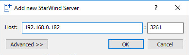
Click OK and Connect button to continue.
27. Right-click the recently created device and select Replication Manager.
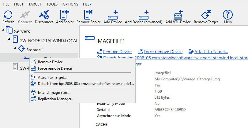
Replication Manager window will appear. Press the Add Replica button.
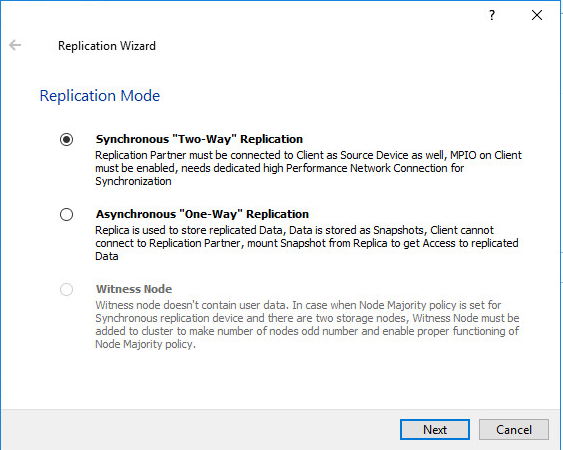
28. Select the Synchronous two-way replication. Click Next to proceed.
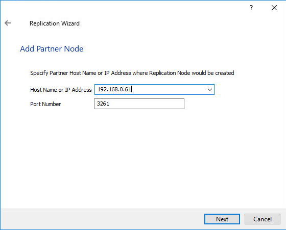
29. Specify the partner server name or IP address.
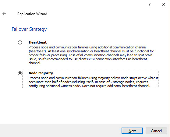
30. Select the Node Majority Failover Strategy and click Next.
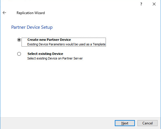
31. Choose Create new Partner Device and click Next.
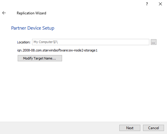
32. Specify the partner device location and it’s target name if necessary. Click Next.
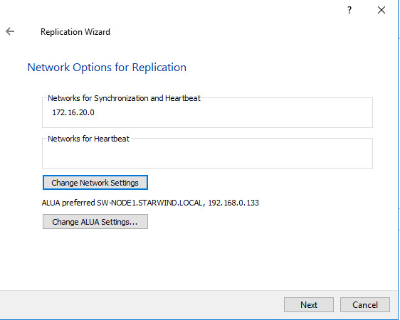
33. Select the synchronization channel for the HA device by pressing the Change network settings button.
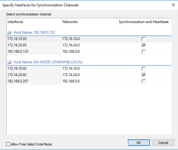
34. Specify the interface for Synchronization. Click OK. Then click Next.
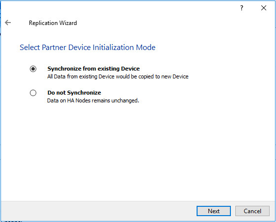
35. Select Synchronize from existing Device as partner device initialization mode and click Next.
36. Press the Create Replica button. Then click Close to close the wizard.
37. The added devices will appear in StarWind Management Console.
Repeat the steps above to create other virtual disks if necessary.
Adding Witness Node
This section describes adding the Witness node that takes part in counting the nodes for the majority, but neither contains data nor is involved in processing requests from clients.
Witness node can be configured on a separate host, or as a virtual machine in a cloud. It requires StarWind Virtual SAN service installed on it.
NOTE: Since the device created in this guide is replicated between 2 active nodes with the Node Majority failover strategy, a Witness node must be added to it.
For devices that have the heartbeat failover strategy or the ones replicated between 3 active nodes, no Witness node is required.
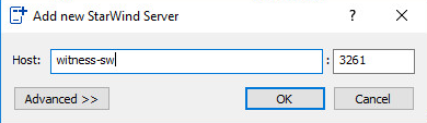
38. Open the StarWind Management Console, right-click on the Servers field and press the Add Server button. Add a new StarWind Server which will be used as the Witness node and click OK.
39. Right-click on the HA device with the configured Node Majority failover policy and select Replication Manager. The Replication Manager window will appear. Press the Add Replica button.
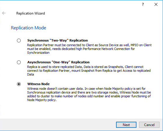
40. Select Witness Node and click Next
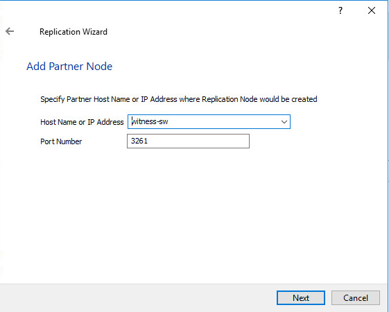
41. Specify the Witness node name or its IP address.
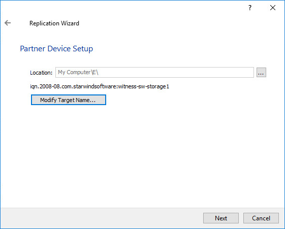
42. Specify the Witness device location and its target name if necessary. Click Next.
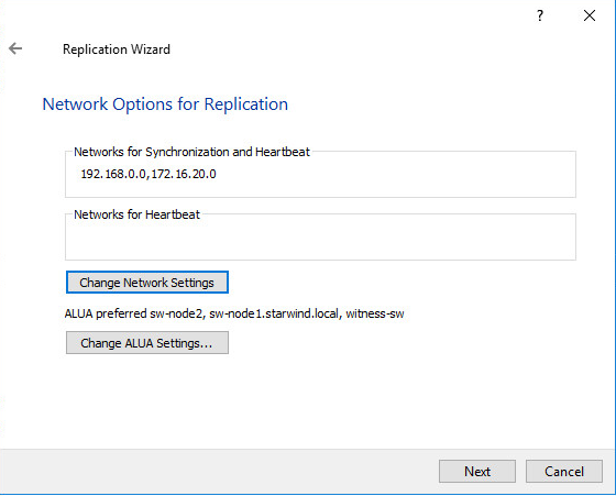
43. For the HA device, select the synchronization channel with the Witness node by clicking on the Change network settings button.
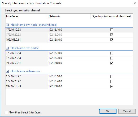
44. Specify the interface for synchronization, confirm, and click Next.
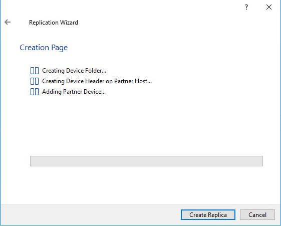
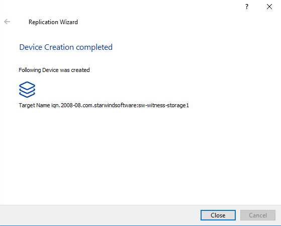
45. Click Create Replica, then close the Wizard by pressing the Close button.
46. Repeat the steps above to create other virtual disks if necessary.
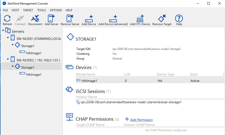
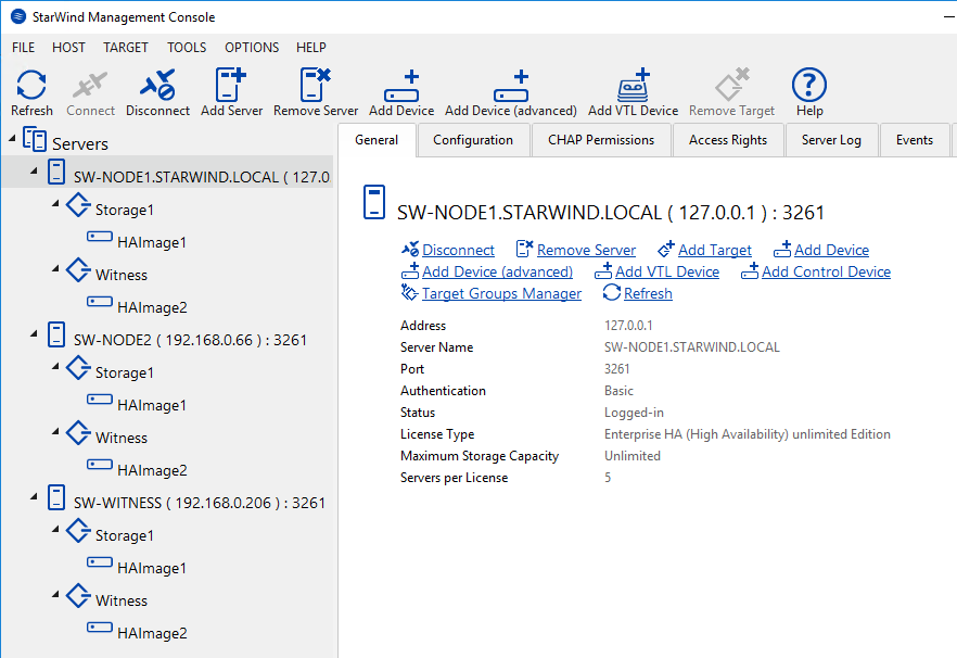
47. Once all devices are created, the StarWind Management Console should look as follows:
CONCLUSION
Node Majority Failover Strategy can be implemented with StarWind Virtual SAN as an alternative to Heartbeat Failover Strategy.
Witness node doesn’t contain user data. It must be added to make the number of nodes odd if Node Majority failover policy is set for the device with the synchronous replication between two nodes. The odd number of nodes grants the proper functioning of the Node Majority failover policy.
Benefits:
- Possibility of a “split brain” is completely excluded;
- An additional communication channel for the heartbeat is NOT required.
Disadvantages:
- In a configuration with two storage nodes, a third node is required;
- If an HA device consists of three storage nodes, or two storage nodes and one witness node, failure of only one node can be tolerated. In case two nodes fail, the third node will also become unavailable to clients’ requests.
