

Installing and Configuring a SQL Server Failover Clustered Instance on Microsoft Azure Virtual Machines
- March 05, 2018
- 52 min read
INTRODUCTION
A SQL Server failover clustered instance is a configuration where all of the nodes of the cluster are connected to the same shared storage. However, when deployed on an Azure virtual machine, the Windows Server Failover Cluster (WSFC) must use Azure-hosted storage with one of the following options, as per Microsoft KB 2721672:
- Application-level replication for a non-shared storage;
- Volume-level replication for a non-shared storage;
- ExpressRoute for a remote iSCSI Target shared block storage;
- Azure Files for a shared file storage.
The Azure-hosted storage used for building a WSFC will leverage StarWindVirtual SAN for the implementation of a volume-level replication.
This guide is intended for experienced Windows system administrators, IT professionals, and SQL Server database administrators who would like to install and configure a 2-node Windows Server 2016 Failover Cluster that will host a SQL Server failover clustered instance (FCI) on Azure virtual machines.
Assumptions
When using this guide, a few assumptions have been made:
- An Azure subscription is available to create the required resources.
- Windows Server 2016 virtual machines with at least 2 network adapters are provisioned for the cluster nodes and are joined to the same Active Directory domain on Azure.
- Configuration of the StarWind Virtual SAN used for the cluster is outside the scope of this document. However, the software will be installed on the cluster nodes.
- Understanding of basic Azure concepts.
- Knowledge of Windows PowerShell scripting and Azure PowerShell Modules.
- MPIO and Failover Clustering features are installed on both cluster Virtual Machines.
Network Architecture Design
A proper network architecture design is a key to successfully implementing a SQL Server failover clustered instance on Azure. Enlist the help of network engineers to make sure that your design complies with your corporate standards and is configured appropriately. Below is the network diagram that will be used to implement the SQL Server failover clustered instance.
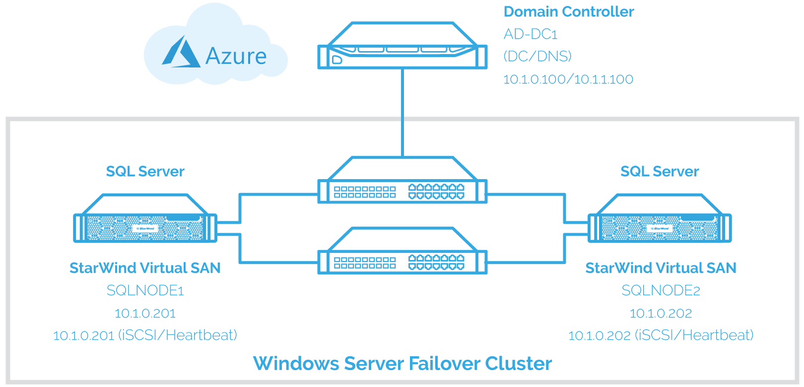
There are at least two virtual network adapters (vNICs) for the WSFC nodes – one for production traffic and one for cluster heartbeat and storage volume replication. It is recommended to have more than two (2) vNICs to achieve quality of service (QoS) and fault tolerance for both the cluster and storage replication. However, there are certain considerations when creating Azure virtual machines with more than one (1) vNIC:
- Azure virtual machines with multiple vNICs must be created in Azure virtual networks (VNets).
- Creation of Azure virtual machines with multiple vNICs is bound by the limitations of the standard VM sizes (SKUs) and existing Azure subscription. For more information on the different SKUs and the maximum number of vNICs per SKU, please refer to Create a VM with Multiple NICs.
The domain controller has two (2) vNICs mainly because it is in the same cloud service as the cluster nodes. A breakdown of the servers, virtual network names, and IP addresses is shown in the table below.
| Hostname | IP Address | Purpose |
| AD-DC1 | 10.1.0.100/10.1.1.100 | Domain Controller/DNS Server |
| SQLNODE1 | 10.1.0.201 | Cluster Node 1 – public traffic |
| 10.1.1. 202 | iSCSI communication | |
| SQLNODE2 | 10.1.0.202 | Cluster Node 2 – public traffic |
| 10.1.1. 201 | iSCSI communication |
Below are the steps that need to be taken for installing and configuring a SQL Server failover clustered instance on Azure virtual machines:
- Creating an Azure cloud-only virtual network (VNet)
- Creating an Azure cloud service
- Creating an Azure storage account
- Creating and configuring Azure virtual machines
- Adding an Azure hosted data disk to the virtual machines used for the WSFC nodes
- Installing and configuring an Active Directory Domain Controller
- Configuring the WSFC Nodes
- Installing and configuring StarWind Virtual SAN
- Discovering iSCSI Target Portals
- Connecting iSCSI Targets and Configuring Multi-pathing
- Initializing and formatting the Disks
- Running the Failover Cluster Validation Wizard
- Creating the Windows Server 2016 Failover Cluster
- Fixing the Windows Server Failover Cluster Client Access Point
- Configuring Cluster Quorum settings
- Installing a SQL Server on a Windows Server 2016 Failover Cluster
- Adding a Node on a SQL Server Failover Clustered Instance
- Creating an Azure Internal Load Balancer
- Updating the SQL Server Failover Clustered Instance Virtual Network Name
Creating an Azure Cloud-Only Virtual Network (VNet) and Public IP Address
An Azure Virtual Network (VNet) allows provisioning and managing virtual private networks (VPNs) in Azure and linking the VPNs with your on-premises network. This also allows network administrators to create solutions and control network topology, including configuration of DNS and IP address ranges.
In this section, Azure cloud-only virtual network with two subnets will be created – one for regular network traffic and another for cluster heartbeat and storage volume replication:
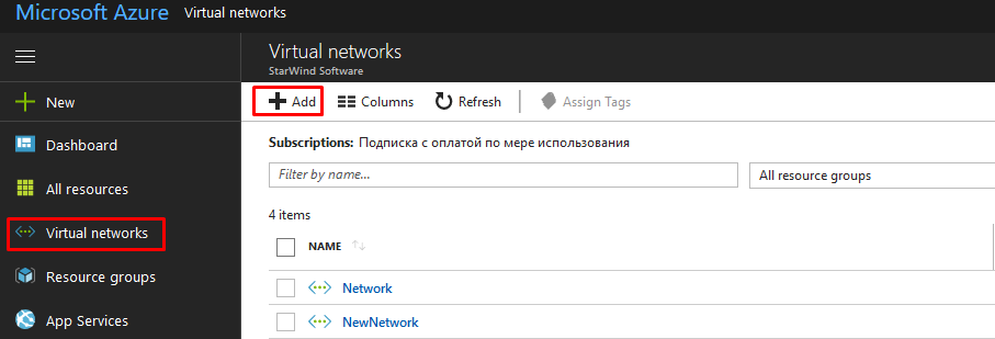
1. Login to the Azure Management portal using your credentials
2. Choose Virtual Network and click Add. This will initiate the configuration wizard.
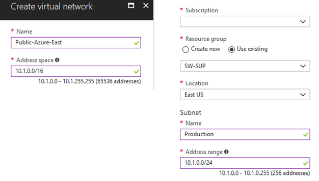
3. In the Virtual Network Details page, enter the following information:
- Name – this is the name you want to use in your virtual network. In this example, we will use Public-Azure-East
4. In the Virtual Network Address Spaces section, configure the following:
For the Address Space section:
- In the Starting IP field, type 10.1.0.0/16 (65535)
- Select subscription
- Location – this is the location of the data center where the virtual network gets created. It is recommended to select the region where you will place all your Azure resources. In this example, we will use East US
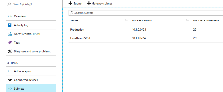
For the Subnet section:
- In the first row, type Production over the existing name add 10.1.0.0/24
Click Create
- Click the add subnet link, type Heartbeat-iSCSI for the name and 10.1.1.0/24 for the starting IP.
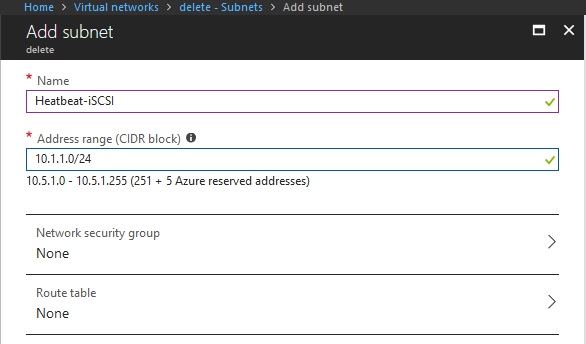
Click the OK button.
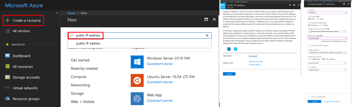
5. To create Public IP Address, click the Create a resource tab. In the new window, type “public IP address” and select it from the drop-down list. On next window, click create, configure the appropriate settings and click create once again as shown below.
Creating an Azure Storage Account
An Azure storage account provides the owner with the access to services in Azure Storage. Your storage account provides the unique namespace for your Azure Storage data objects. Billing for Azure Storage usage is based on the storage capacity, replication scheme, storage transactions, and data flow.
This section describes how to create an Azure storage account to store all the virtual machines created and the storage volume attached to them:
6. Login to the Azure Management portal using your credentials.
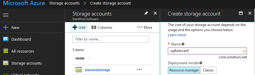
7. Select Storage Accounts and click Add.
- In the Name field, type SQLFailover. This will be the public DNS name that you will use to connect to the Azure storage account in the form Name.core.windows.net
- In the Region or Affinity Group drop-down box, select East US
- In the Replication drop-down box, select Geo-Redundant to provide maximum durability for your data.
8. Click the Create Storage Account tab to create the Azure storage account.
Creating and Configuring the Azure Virtual Machines
This section describes how to create Azure virtual machines via GUI interface. For this purpose, three (3) Azure virtual machines will be created – one for the domain controller and two (2) for the nodes of the SQL Server failover clustered instance. All the virtual machines will have 2 vNICs and will use the virtual network (VNet,) cloud service and storage account created in the previous sections. All the Azure virtual machines will use the latest Windows Server 2016 image available. While the IP addresses appear to be statically assigned, they are DHCP-requested from the Azure VNet subnet. This ensures that the Azure virtual machine will be assigned a specific IP address during provisioning. However, it is not a guarantee. A more detailed description of static IP addresses in Microsoft Azure is described in Static IP, Reserved IP and Instance Level IP in Azure.
Creating a Virtual Machine
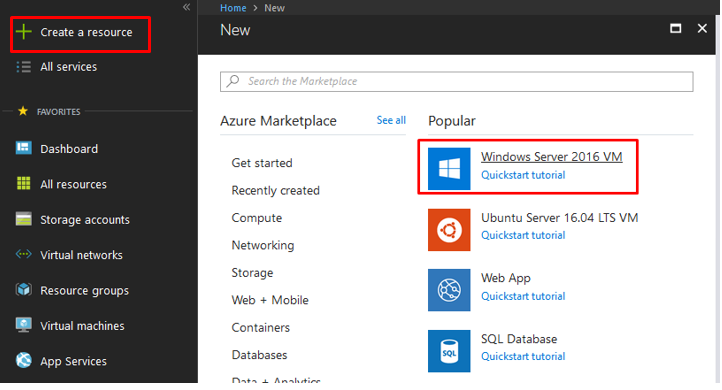
9. To create a Virtual Machine, click Create a resource and select “Windows Server 2016 VM”.
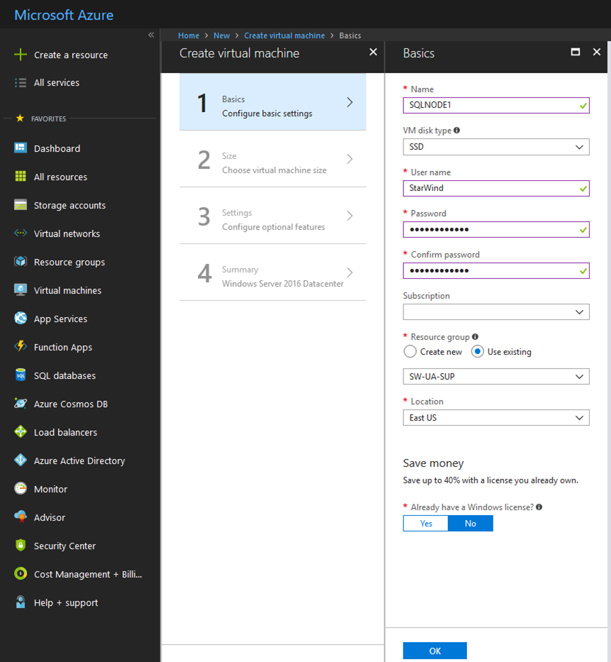
10. On the next window, fill in the required details as shown below and click OK.
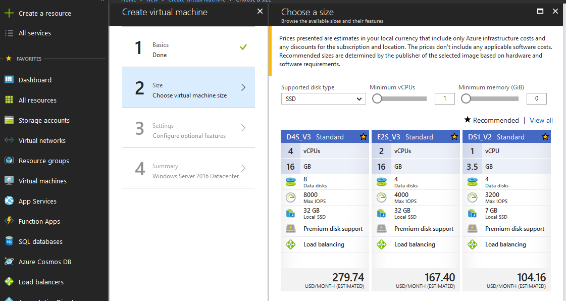
11. Select the required Virtual Machine.
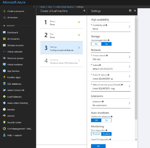
12. On the Configure optional features tab, verify that everything is correct and click OK.
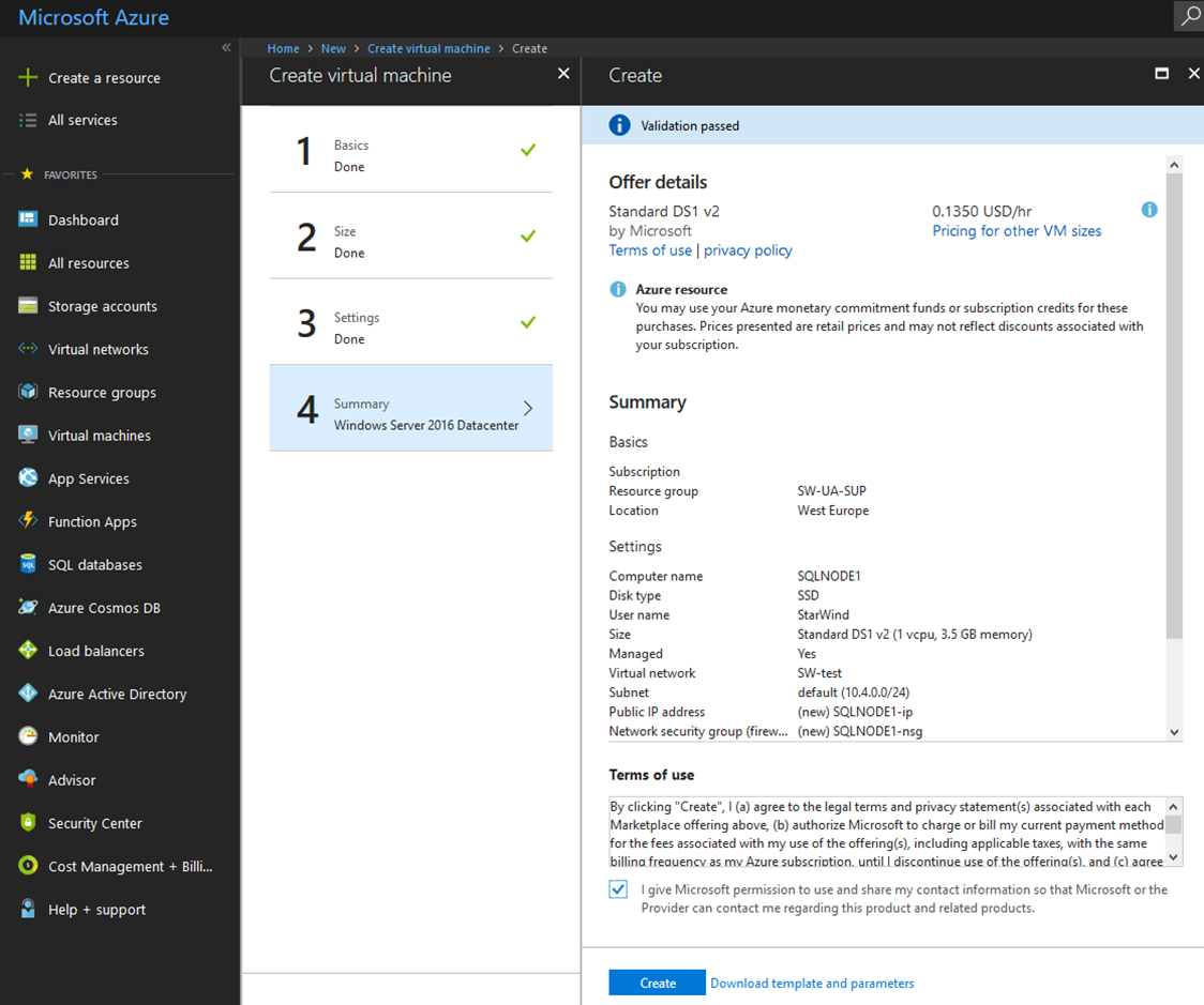
13. In the Summary tab, tick the checkbox for “terms of use” and click Create.
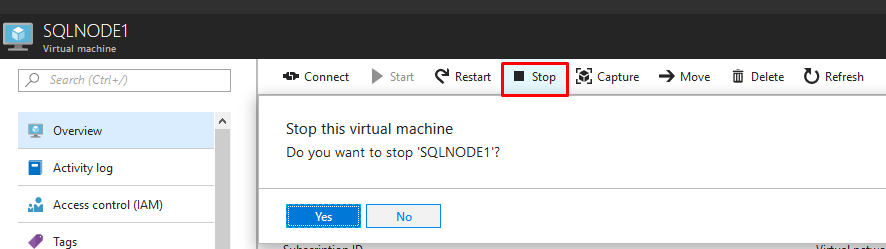
14. When the deployment is finished, Stop the Virtual Machine.
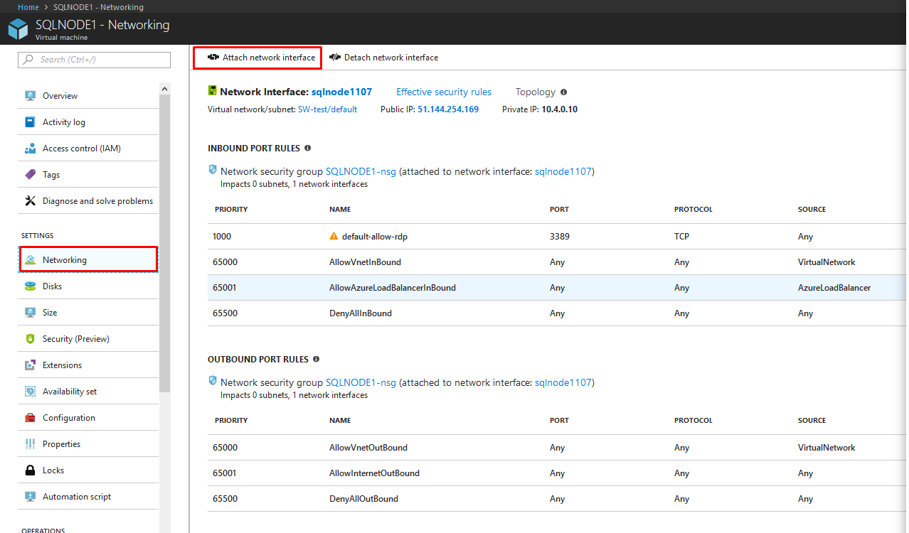
15. Once it’s stopped, select the Networking tab and click Attach network interface.
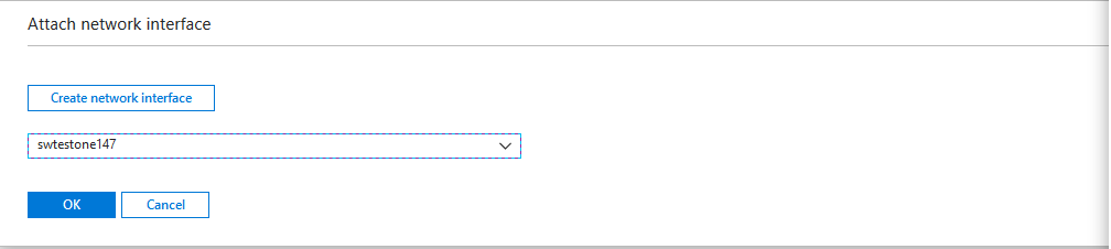
16. Select the second network, click OK, and wait for attachment to finish.
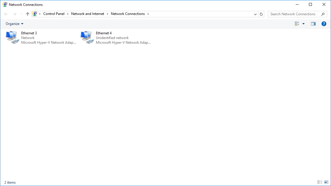
17. Start the Virtual Machine, click Connect, logon using the credentials you provided earlier, and check if two NICs have been added.
18. Perform the same steps for the other Virtual Machines.
Adding an Azure-Hosted Data Disk to the Virtual Machines Used for the WSFC Nodes
Once the Azure virtual machines have been created, add the Azure-hosted data disks that will be used to store the StarWind virtual disks. Only the virtual machines that will be used to build the WSFC need the disks.
To add an Azure-hosted data disk and attach it to the virtual machine, follow the next steps.
19. Log in to the Azure Management portal using your credentials.
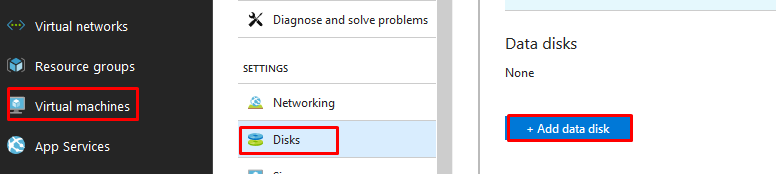
20. Click the Virtual Machines tab and select SQLNODE1.
21. Click Disks and click Add data disk.
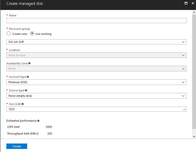
22. In the Attach an Empty Disk dialog box:
- In the File Name field, type an appropriate name
- In the Size (GB) field, specify the size of the data disk
23. Click the Check icon to create the Azure-hosted data disk and attach it to the virtual machine.
Repeat the process to add an Azure-hosted data disk to the SQLNODE2 virtual machine.
Alternatively, you can use the example PowerShell script below to create and add the Azure-hosted data disks to the virtual machines. Parameters used in the example are commented on how they are used. All code is written as single-line. Format appropriately in code/script editor.
$ClusterDisk1="ClusterDisk_SQLNODE1" #name of Azure hosted data disk for SQLNODE1

$ClusterDisk2="ClusterDisk_SQLNODE2" #name of Azure hosted data disk for SQLNODE1

#Attach a new 20GB Azure hosted data disk for SQLNODE1

Get-AzureVM $cloudSvcName -Name $WSFCVMNode1 | Add-AzureDataDisk -CreateNew - DiskSizeInGB 20 -DiskLabel $ClusterDisk1 -LUN 0 | Update-AzureVM

#Attach a new 20GB Azure hosted data disk for SQLNODE1

Get-AzureVM $cloudSvcName -Name $WSFCVMNode2 | Add-AzureDataDisk -CreateNew - DiskSizeInGB 20 -DiskLabel $ClusterDisk2 -LUN 0 | Update-AzureVM
Installing and Configuring an Active Directory Domain Controller
This section describes how to install and configure an Active Directory domain controller in Microsoft Azure.
While this document is not designed as a guide for Active Directory domain services, it is important to have an Active Directory domain to create a SQL Server failover clustered instance running on top of a Windows Server Failover Cluster. For this purpose, a Windows PowerShell script will be run inside the virtual machine to install and configure an Active Directory domain controller.
24. Login to the Azure Management portal using your credentials.
25. Click the Virtual Machines tab, and select AD-DC1.
26. On the command bar, click Connect. This will prompt you to download a Remote Desktop connection file.
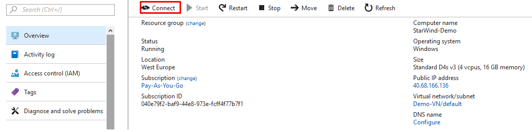
27. Login to the virtual machine and run the PowerShell script below to install and configure an Active Directory domain controller. Provide a password when prompted for the SafeModeAdministratorPassword. The virtual machine will reboot as part of the configuration.
$NTDSpath = "C:\Windows\NTDS"
$SYSVOLpath = "C:\Windows\SYSVOL"

Install-WindowsFeature –Name AD-Domain-Services -includemanagementtools Install-ADDSForest -DatabasePath $NTDSpath -LogPath $NTDSpath -SysvolPath $SYSVOLpath - DomainName "TESTDOMAIN.COM" -InstallDns -Force -Confirm:$false
28. After the script finishes, run the PowerShell script below to remove the forwarder from the DNS server that was created as part of the installation of an Active Directory domain controller. This is because the virtual machine originally uses the standard Azure DNS. Configuring it as a DNS server for the Active Directory domain, limits the DNS name resolution.
Get-DnsServerForwarder | Remove-DnsServerForwarder -Force
Configuring the Windows Server Failover Cluster Nodes
This section describes how to configure the Windows Server Failover Cluster (WSFC) nodes.
Once the Active Directory domain controller is available, the WSFC nodes can be configured.
A high-level overview of the following tasks is listed below.
- Add and install the Failover Clustering, Multi-Path IO and .NET Framework 3.5 features
- Assign the IP address of the Active Directory-integrated DNS server to the Production subnet of the Public-Azure-East Azure VNet. This is to make sure that the virtual machine can join to the domain via the appropriate IP address
- Format the attached Azure-hosted data disk
- Join the virtual machine to the domain
To configure the WSFC Nodes:
29. Log in to the Azure Management portal using your credentials.
30. Click the Virtual Machines link and select SQLNODE1.
31. On the command bar, click Connect. You will be prompted to download a Remote Desktop connection file.
32. Login to the virtual machine using the credentials that you used when creating VMs.
33. Run the PowerShell script below to perform the tasks listed in the high-level overview. Provide the domain administrator credentials that you used when creating the Active Directory domain controller. This can also be done through GUI. The virtual machine will reboot as part of the configuration.
$PrimaryIP_DC = "10.1.0.100" #IP address of the domain controller/DNS server
$ClusterDisk1 = "ClusterDisk_Node1" #name of the Azure hosted data disk
#Add Failover Clustering and .NET Framework 3.5 (in preparation for installing SQL Server)
Install-WindowsFeature -Name Failover-Clustering -IncludeManagementTools
Install-WindowsFeature –Name NET-Framework-Core Enable-WindowsOptionalFeature –Online –FeatureName MultiPathIO
#Assign IP address of DNS server on the vNIC assigned on the Production subnet, not the Heartbeat_iSCSI subnet
#Identify the interface index of the vNIC assigned on the Production subnet
$interfaceIndex=(Get-NetIpAddress | Where {$_.IpAddress -like "10.1.0.*"}).InterfaceIndex
#Assign IP address of the DNS Server
Set-DNSClientServerAddress –InterfaceIndex $interfaceIndex -ServerAddresses $PrimaryIP_DC
#Format attached Azure hosted data disk and assign drive letter D:\
Get-Disk | Where partitionstyle -eq 'RAW' | Initialize-Disk -PartitionStyle GPT -PassThru | New-Partition -UseMaximumSize -DriveLetter G
Format-Volume -FileSystem NTFS -NewFileSystemLabel $ClusterDisk1 -DriveLetter "D" - AllocationUnitSize 65536 -Confirm:$false
#Join virtual machine to TESTDOMAIN.com domain
Add-Computer -Credential $domainCredentials -DomainName TESTDOMAIN.COM
#Reboot VM
Restart-Computer
34. Repeat the steps above in this section on another SQL node.
Enabling Multipath Support
35. Open the MPIO Properties manager: Start -> Windows Administrative Tools -> MPIO. Alternatively, run the following PowerShell command:
mpiocpl
36. In the Discover Multi-Paths tab, tick the Add support for iSCSI devices checkbox and click Add.
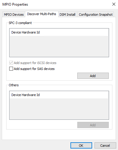
37. When prompted to restart the server, click Yes to proceed.
NOTE: Repeat the procedure on the other server.
Installing and Configuring StarWind Virtual SAN
Download the latest version of StarWind Virtual SAN on the Azure virtual machines and proceed with the installation.
The process outlined below should be performed on both SQLNODE1 and SQLNODE2.
To install StarWind Virtual SAN, run the setup file on SQLNODE1.
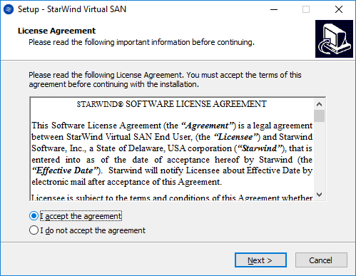
38. In the License Agreement dialog box, select I accept the agreement and click Next.
39. In the Information dialog box, click Next.
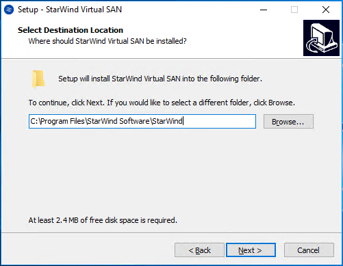
40. In the Select Destination Location dialog box, provide the file system path where you want to store the StarWind Virtual SAN binaries and executables. Click Next.
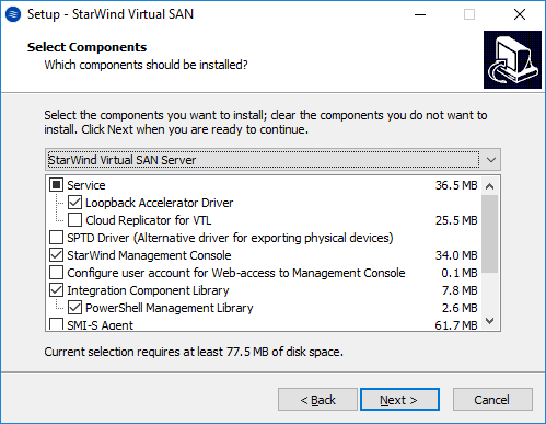
41. In the Select Components dialog box, verify that StarWind Virtual SAN Server is selected in the drop-down list and click Next.
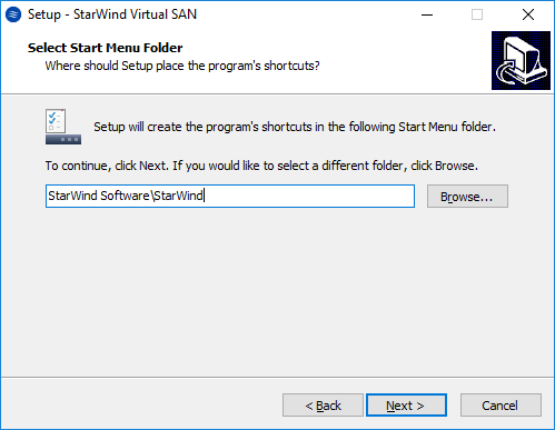
42. In the Select Start Menu Folder dialog box, verify the location of the shortcut to launch StarWind Virtual SAN. Click Next.
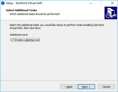
43. In the Select Additional Tasks dialog box, validate the selection by checking the Create a desktop icon check box. Click Next.
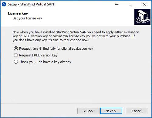
44. In the License Key dialog box, provide the appropriate license key. Click Next.
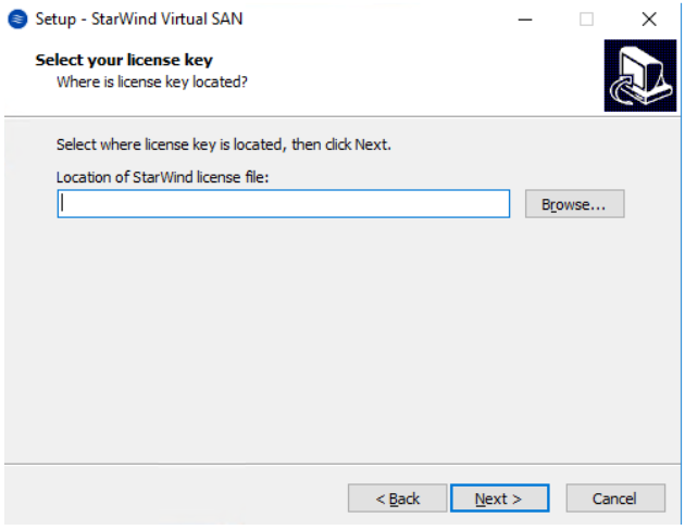
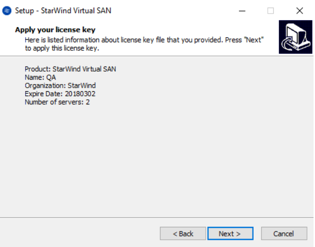
45. Click Browse to locate the license file. Press Next to continue.
46. Review the licensing information. Click Next to continue
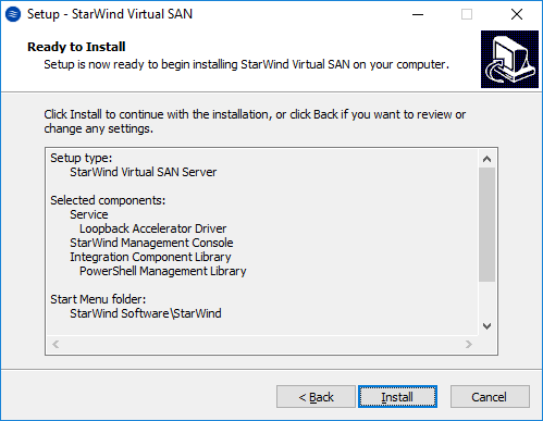
47. In the Ready to Install dialog box, verify that all configuration settings you’ve provided are correct. Click Install.
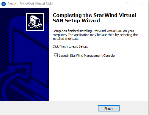
48. In the Completing the StarWind Virtual SAN Setup Wizard dialog box, click Finish. This completes the installation of StarWind Virtual SAN and will also launch the StarWind Management Console.
After completing the installation, repeat all the steps to install StarWind Virtual SAN on SQLNODE2
Configuring StarWind Virtual SAN
After StarWind Virtual SAN has been installed on both SQLNODE1 and SQLNODE2, a hyper-converged storage can be configured for the Windows Server Failover Cluster. These steps can be performed on any of the virtual machines with StarWind Virtual SAN installed. These steps will be performed on SQLNODE1.
49. Open the StarWind Management Console. It will ask you to specify the default storage pool on the server you’re connecting to for the first time. Click the Yes button to select the D drive.

This is the Azure Data Disk that has been added in the section Adding an Azure hosted data disk to the virtual machines used for the WSFC nodes.
50. In the StarWind Management Console, add server SQLNODE1 and SQLNODE2.

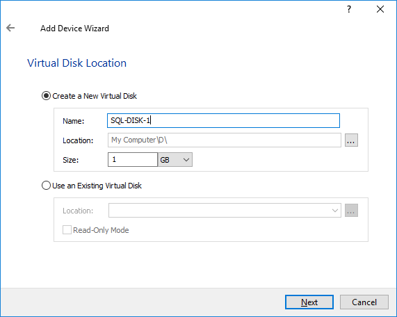
51. Connect the servers and select the StarWind server where the device is to be created. Press the Add Device (advanced) button on the toolbar. Add Device Wizard will appear. Select Hard Disk Device and click Next. Choose the Virtual Disk option, click Next, and specify the Virtual disk location, name, and size.
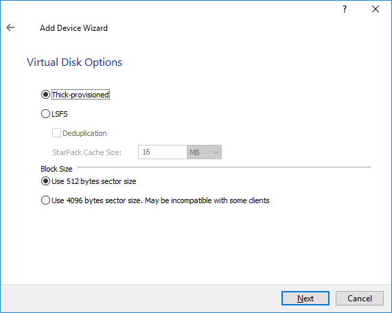
52. Specify the virtual disk options and click Next.
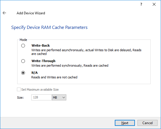
53. Define the caching policy and specify the cache size if necessary.
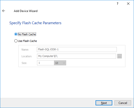
54. Define the Flash Cache Parameters and size if necessary. Choose the SSD location in the wizard. Click Next to continue.
55. Specify the target parameters.
Select the Target Name checkbox to customize the target name. Otherwise, the name will be generated automatically basing on the target alias.
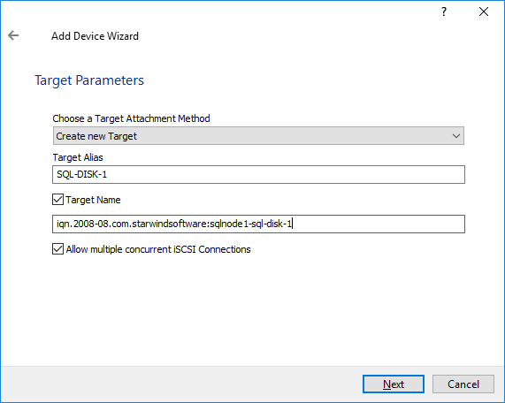
Click Next to continue. Click Create to add a new device and attach it to the target.
Then click Close to close the wizard.
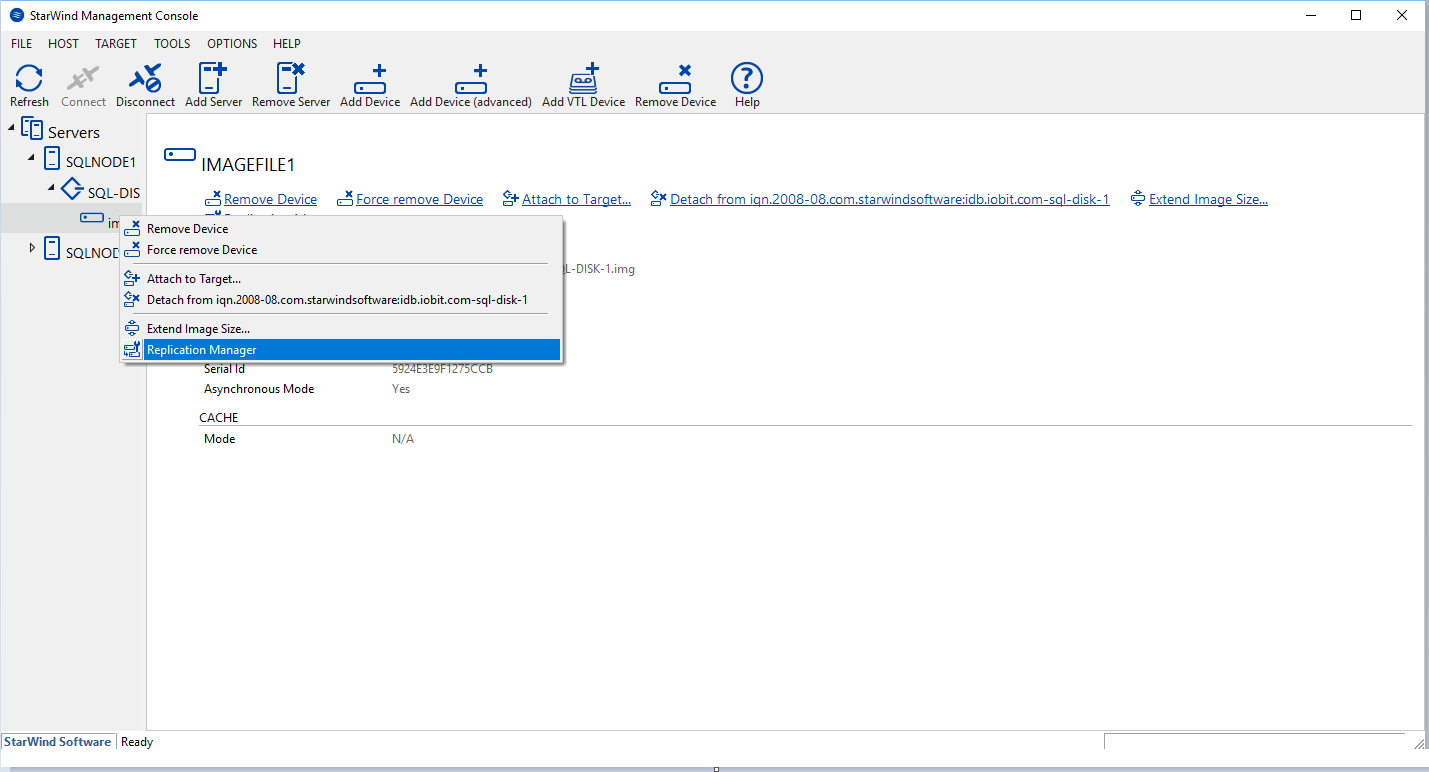
56. Right-click the device you have just created and select Replication Manager.
57. The Replication Manager window will appear. Press the Add Replica button.
58. Select Synchronous “Two-Way” Replication.
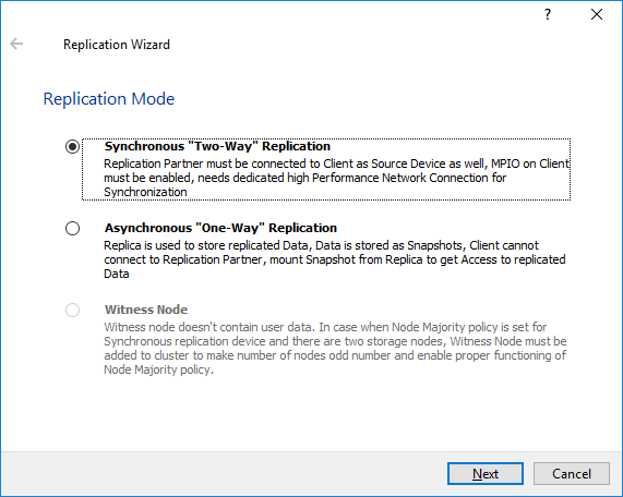
Click Next to proceed.
59. Specify the partner server IP address.
The default StarWind management port is 3261. If you have configured a different port, please, type it in the Port number field.
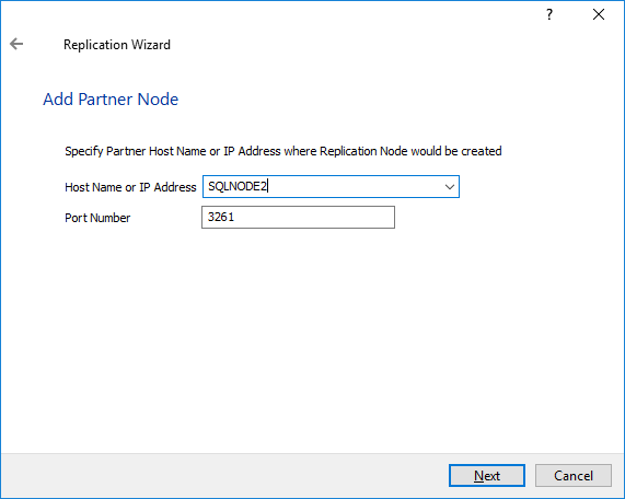
Click Next.
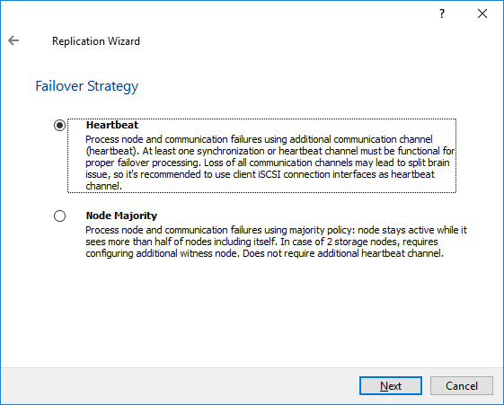
60. Choose Heartbeat Failover Strategy and click Next.
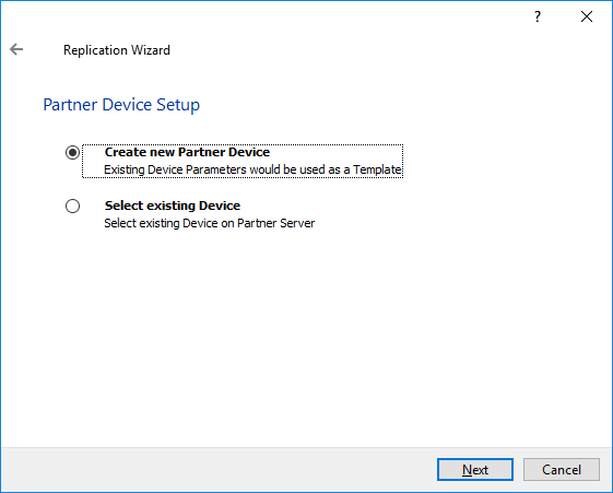
61. Choose Create new Partner Device and click Next.
62. Specify partner device location if necessary. You can also modify the target name of the device.
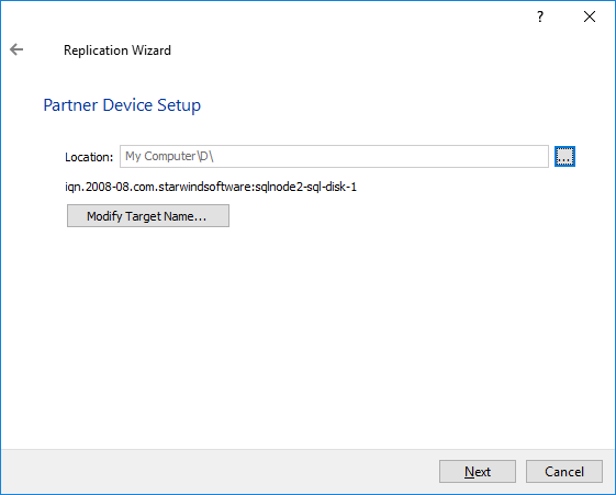
Click Next.
63. On the next screen, the synchronization and heartbeat channels for the HA device can be selected and the ALUA settings modified.
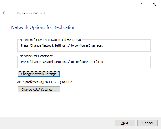
64. Click Change network settings and specify the interfaces for synchronization and Heartbeat.
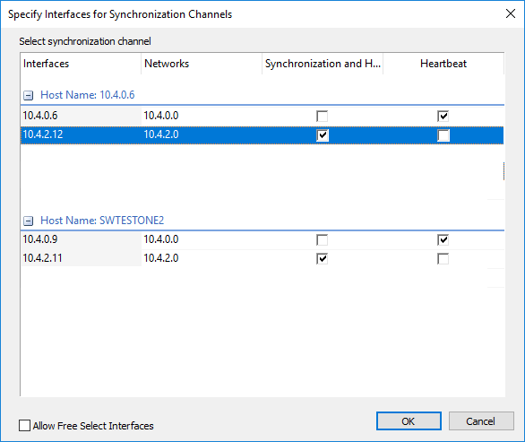
NOTE: It is recommended configuring Heartbeat and iSCSI channels on the same interfaces to avoid the split-brain issue.
Complete the network selection for Replication and click Next.
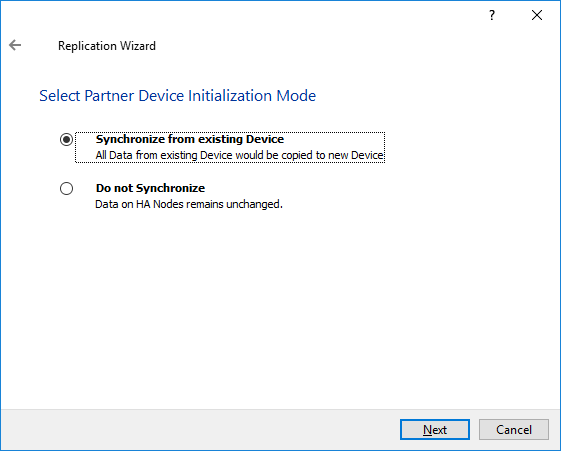
65. Select the partner device initialization mode as Synchronize from existing Device and click Next.
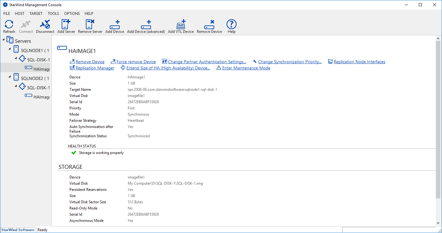
66. Press the Create Replica button and click Close. The added devices will appear in the StarWind Management Console.
Discovering Target Portals
In this section, the iSCSI storage will be connected to the servers added to the cluster.
NOTE: Windows Server 2016 comes with iSCSI Initiator software that enables connection of a Windows host to an iSCSI storage array using network adapters. In this example, the iSCSI target is the same as the WSFC nodes. You can launch the tool from the Server Manager dashboard, by selecting Tools and choosing iSCSI Initiator.
Also, make sure that the Windows Firewall is configured to allow iSCSI traffic on both SQLNODE1 and SQLNODE2.
The steps below are performed initially on SQLNODE1.

You will get a message saying that the Microsoft iSCSI service is not running. Simply click Yes to continue.
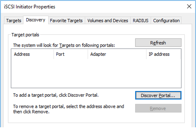
67. In the iSCSI Initiator Properties window, select the Discovery tab.
68. Click the Discover Portal… button. The Discover Target Portal dialog box appears.
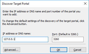
69. Type in the IP address of the partner node you will use to connect to the highly available iSCSI devices. For this example, a loopback IP address of SQLNODE1 is used, which is 127.0.0.1.
70. Click Advanced and Select Microsoft ISCSI Initiator as your Local adapter.
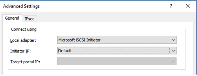
Click OK. Then click OK again to close the Discover Target Portal dialog box.
71. Click the Discover Portal button once again. The Discover Target Portal dialog appears.
72. Type in the IP address of the partner node you will use to connect to the HA iSCSI devices. For this example, the IP address of SQLNODE2 is 10.1.1.202.
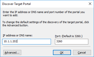
Click the Advanced button.
73. Select Microsoft ISCSI Initiator as your Local adapter. Select the Initiator IP in the same subnet as the IP address from the previous step. For this example, the second IP address of SQLNODE1 that communicates to the Initiator IP is 10.1.1.201.
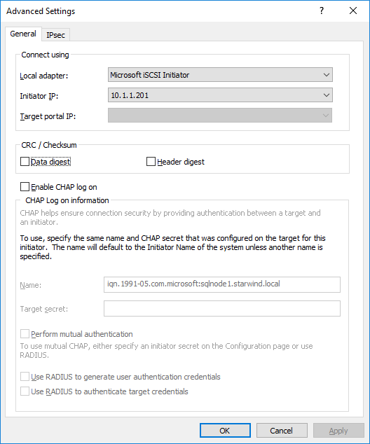
Click OK. Then click OK again to close the Discover Target Portal dialog box.
SQLNODE1 should be connected to both iSCSI Targets via the following target portals.
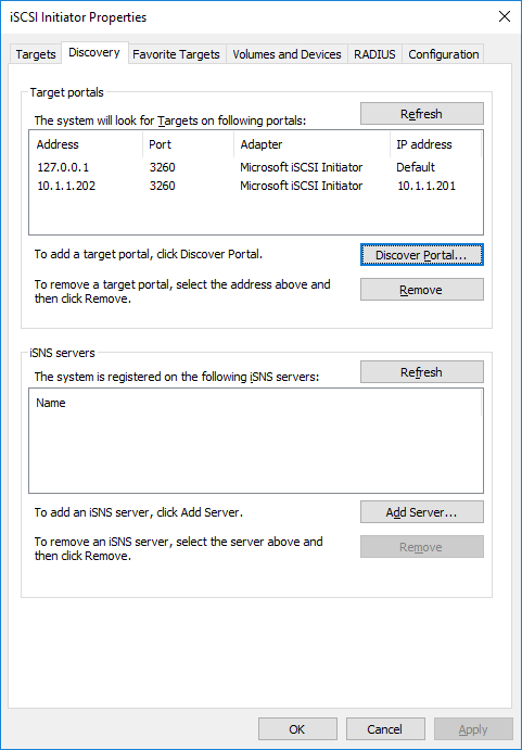
74. Repeat the same steps for the second node SQLNODE2 until all the target portals have been added. Note that SQLNODE2 should also be connected to both iSCSI Targets via the following target portals.

Connecting Targets and Configuring Multipathing
This section describes how to connect the servers to the iSCSI targets and configure multipathing:
NOTE: The steps below are performed initially on SQLNODE1.
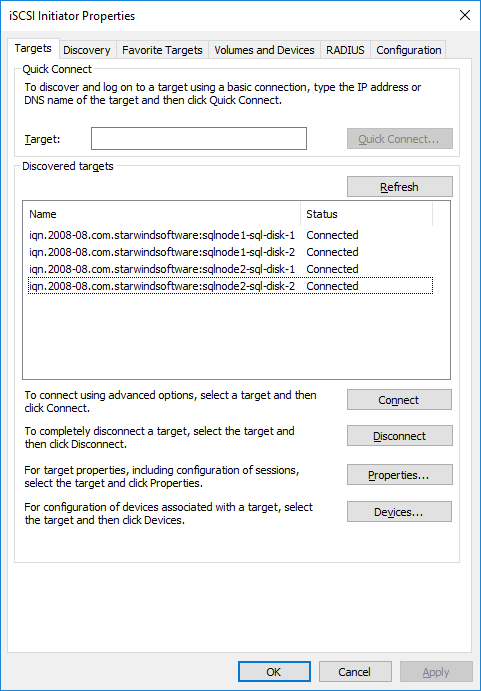
75. In the iSCSI Initiator Properties window, select the Targets tab. The iSCSI targets configured should be listed in the Discovered Targets section.
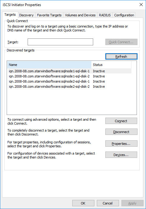
76. Select the first target in the list and click Connect.
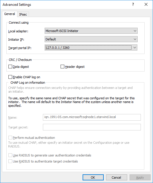
77. Enable both checkboxes and click Advanced…

78. Select Microsoft iSCSI Initiator in the Local adapter dropdown menu. In Target portal IP, select 127.0.0.1. Confirm the actions.
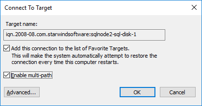
79. Select the partner target from another StarWind node (SQLNODE2) and click Connect. In this case, 10.1.1.x subnet is used to connect the target.
80. Enable both checkboxes and click Advanced…
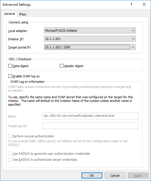
81. Select Microsoft iSCSI Initiator in the Local adapter dropdown menu. In the Initiator IP field, select the IP address for the iSCSI channel. In the Target portal IP, select the corresponding portal IP from the same subnet. Confirm the actions.
82. Repeat the steps above for all remaining HA device targets. The result should look like in the screenshot below.

83. Repeat the steps described in this section on SQLNODE2.
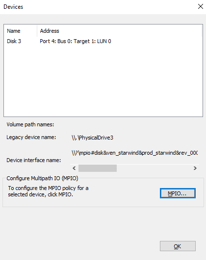
84. Configure the MPIO policy for each target as the Failover Only. Select the target located on the local server and click Devices.
85. In the Devices dialog, click MPIO.
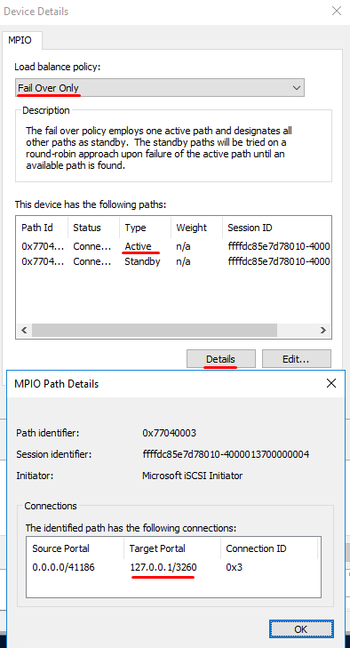
86. Select the appropriate load balancing policy.
NOTE: In case the Failover Only MPIO policy is used, be sure to check that the local path (127.0.0.1) is set to Active, while the partner connection is set to Standby.
Initializing and Formatting the Disks
This section describes how to initialize and format the iSCSI disks. The tool can be launched by navigating to the Server Manager dashboard, Tools, and Computer Management.
NOTE: Going through the disk initialization process is a great way to validate whether or not the storage replication process works as per vendor specification. Disk configuration changes made on one of the cluster nodes should be replicated over to the other nodes within the cluster. These steps must be performed on both servers that will act as nodes in your failover cluster. The steps below are performed on SQLNODE1.
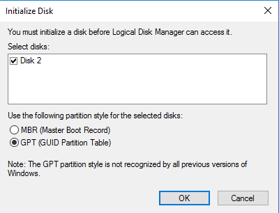
87. Open the Disk Management tool.
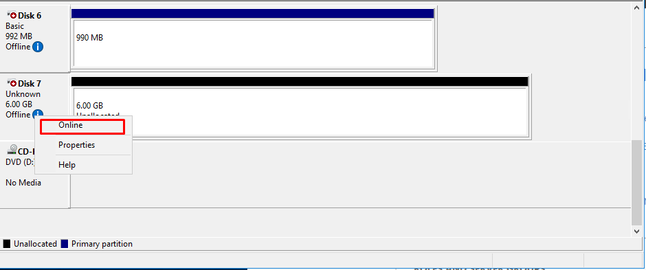
88. When the Initialize Disk dialog box appears, make sure that all iSCSI disks previously configured are selected. Click OK to initialize as GPT.
89. Right-click any of the disks that should be configured and select Online.
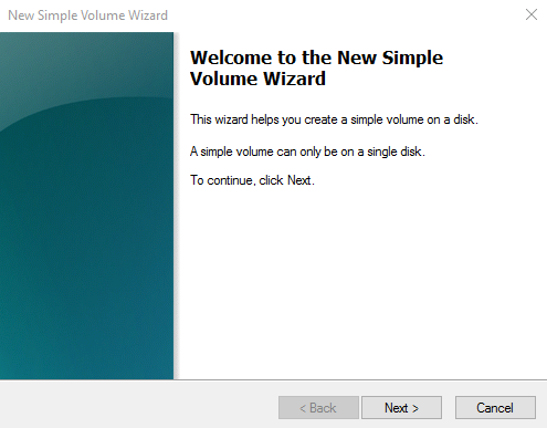
90. To create a disk partition, right-click the unallocated space and select New Simple Volume.
91. In the Welcome to the New Simple Volume Wizard dialog box, click Next.
92. In the Specify Volume Size dialog box, enter the volume size and click Next.
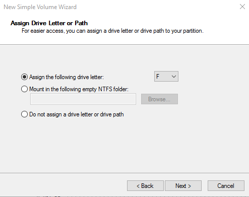
93. In the Assign Drive Letter or Path dialog box, specify the required drive letter and click Next.
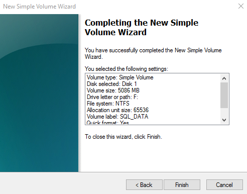
94. In the Format Partition dialog box:
- Make sure that the file system selected is NTFS.
- To follow Microsoft best practices on allocation unit size, select 64K.
- In the Volume label text box, enter the appropriate name. For this example, SQL_DATA is used. Take note of this volume label because this will be used to verify the configuration on the other cluster node.
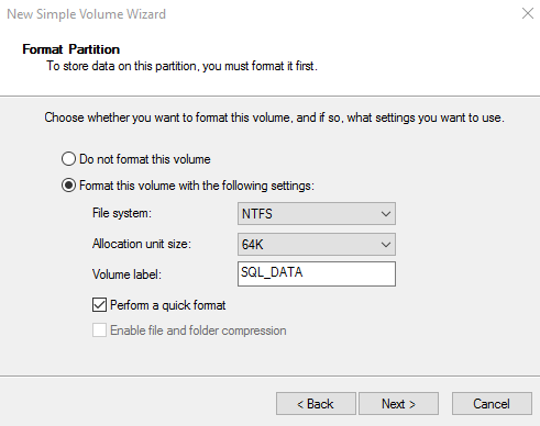
Click Next.
95. In the Completing the New Simple Volume Wizard dialog box, review the settings and click Finish.
96. Repeat the steps above on all of the iSCSI disks that should be configured as part of the cluster.
97. Repeat the steps described in this section on SQLNODE2. No need to initialize the iSCSI disks.
Running the Failover Cluster Validation Wizard
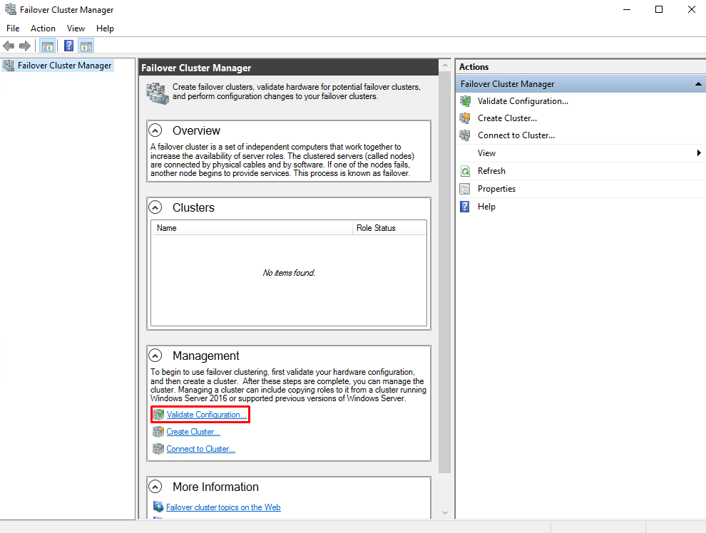
This section describes how to run the Failover Cluster Validation Wizard from the Failover Cluster Management console. To launch the tool, navigate to the Server Manager dashboard, click Tools, and select Failover Cluster Manager.
NOTE: These steps can be performed on any of the servers that will act as FC members. The steps below are performed on SQLNODE1.
98. In the Failover Cluster Management console, under the Management section, click the Validate Configuration option. This will run the “Validate a Configuration Wizard”.
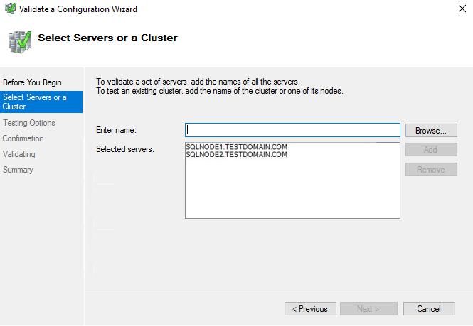
99. In the Select Servers or a Cluster dialog box, enter the hostnames of the nodes to be added as members of the cluster. Click Next.
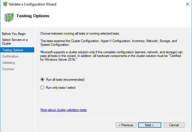
100. In the Testing Options dialog box, click Next to run all the necessary tests to validate the configuration.
101. In the Confirmation dialog box, click Next. This will run all the necessary validation tests.
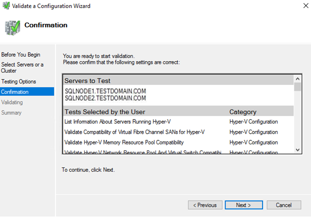
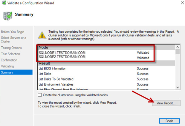
102. In the Summary dialog box, verify that the nodes are validated and all the tests are passed successfully. Click Finish to create the Windows Server Failover Cluster.
NOTE: The Cluster Validation Wizard may report Warning messages pertaining to storage. These warnings can be ignored since the replicated storage is used instead of shared disks. In general, resolve all errors prior to proceeding with the next steps.
Creating the Windows Server 2016 Failover Cluster Using GUI
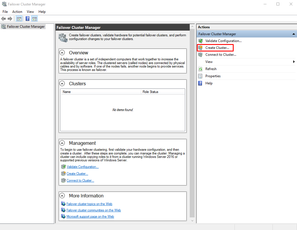
This section describes how to create a Windows Server 2016 Failover Cluster from the Failover Cluster Management console. To launch the tool, navigate to the Server Manager dashboard, click Tools, and select Failover Cluster Manager. Alternatively, the Create Cluster Wizard will start automatically after the Failover Cluster Validation Wizard runs the first time.
NOTE: These steps can be performed on any of the servers that will act as WSFC nodes. The steps below are performed on SQLNODE1.
103. Under the Management section, click the Create a Cluster link. This will run the Create Cluster Wizard.
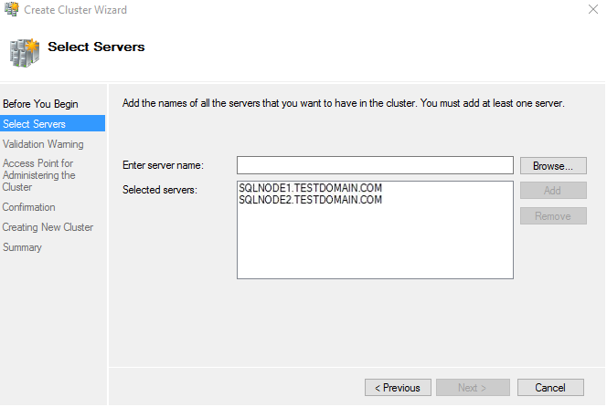
104. In the Select Servers dialog box, enter the hostnames of the nodes to be added as members of the cluster. Click Next.
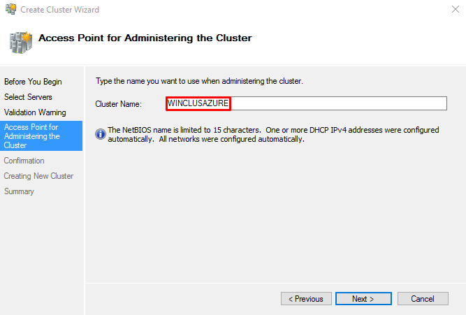
105. In the Access Point for Administering the Cluster dialog box, enter the WSFC virtual hostname/client access point that will be used to administer the cluster. The WSFC will use a DHCP-assigned IP address for the virtual hostname since both SQLNODE1 and SQLNODE2 use DHCP-requested IP addresses, not statically assigned. Click Next.
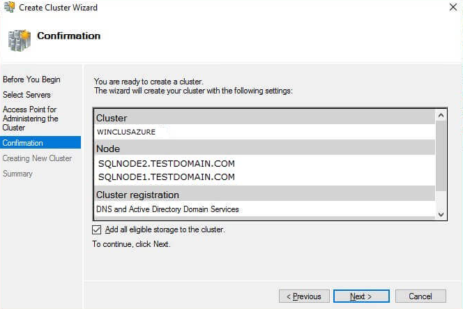
106. In the Confirmation dialog box, click Next. This will configure Failover Clustering on both nodes of the cluster. Add the configured replicated storage, add Active Directory and DNS entries for the WSFC virtual hostname/client access point.
107. In the Summary dialog box, click View Report to verify that the Failover Cluster has been created successfully.
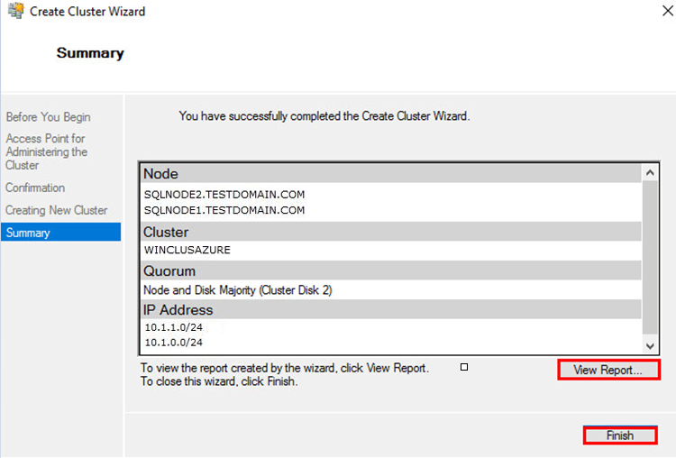
NOTE: The virtual IP address of the WSFC virtual hostname/client access point should be configured. Since the configuration used in this guide has two (2) vNICs, the cluster will assign a virtual IP address for both of them. Only one virtual IP address is required for the WSFC. Also, Azure will attempt to assign an IP address that is currently used by one of the virtual machines. This makes one of the virtual machines inaccessible via Remote Desktop or any other services running on it like StarWind Virtual SAN. Therefore, an unused IP address should be assigned to the WSFC client access point to resolve this conflict.
As a best practice, rename all the clustered storage and networks for ease of identification during the installation of the SQL Server failover cluster instance.
Fixing the Windows Server Failover Cluster Client Access Point
This section describes how to fix the Windows Server Failover Cluster virtual host name/client access point. Since Azure assigned a duplicate IP address for the WSFC virtual host name/client access point, a new IP address must be reassigned from the address pool of the Production subnet of the Public-Azure-East Azure VNet. This task is performed using the Failover Cluster Manager console.
NOTE: These steps can be performed on any of the servers that will act as WSFC nodes. The steps below are performed on SQLNODE1.
108. Open the Failover Cluster Manager console in the Administrator mode.
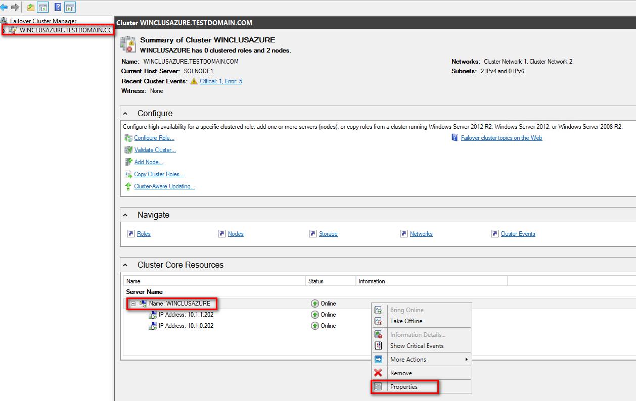
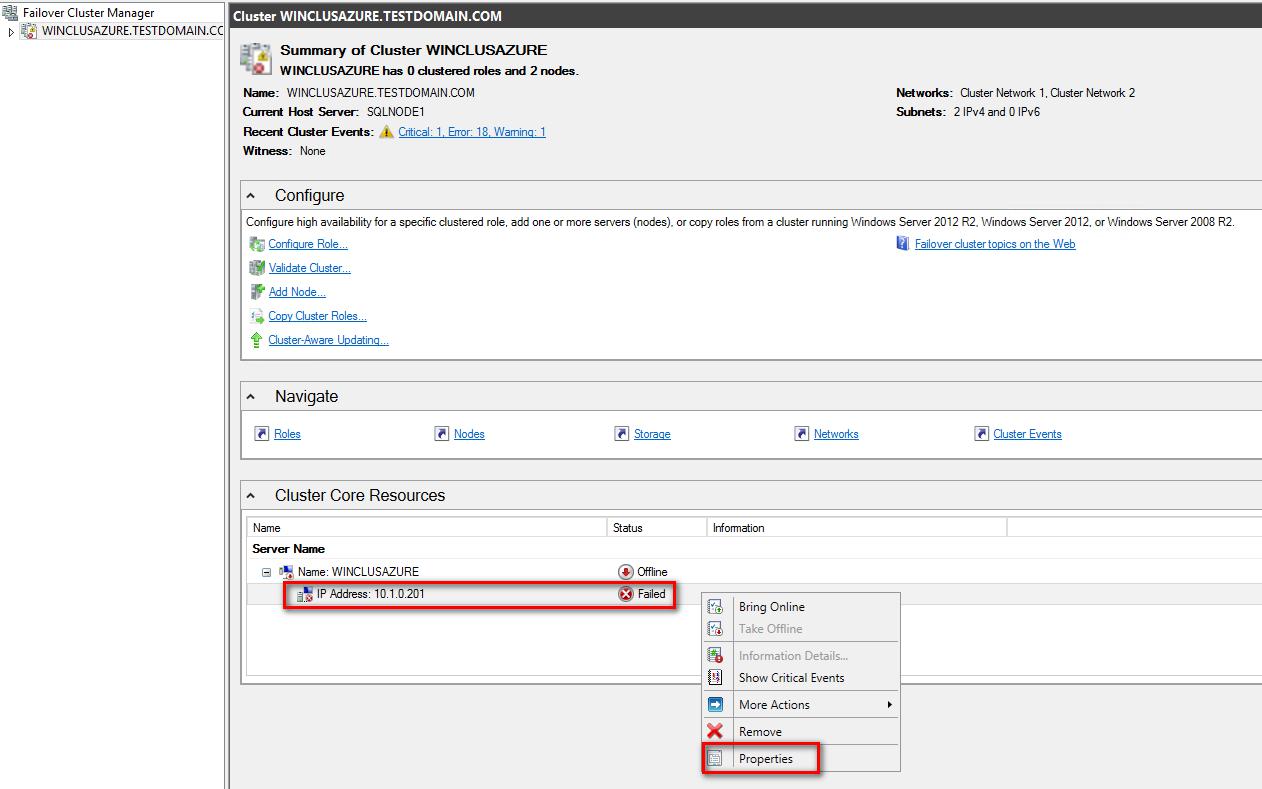
109. In the Cluster Core Resources section, select the name of the WSFC virtual host name/client access point.
110. Right-click and select Properties.
111. In the WINCLUSTERAZURE Properties dialog box:
- In the General tab, under the IP Addresses section, select the IP address corresponding to the Heartbeat-iSCSI subnet of the Public-Azure-East Azure VNet – 10.1.1.0/24. Click Remove. This will remove the virtual IP address assigned on the Heartbeat-iSCSI vNIC.
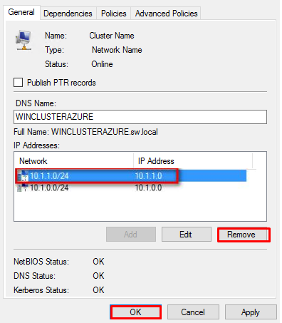
- Click OK.
- When prompted to confirm action, click Yes. This will take the WSFC offline since the remaining virtual IP address is a duplicate IP address from one of the virtual machines.
112. In the Cluster Core Resources section, select the remaining virtual IP address of the WSFC virtual host name/client access point.
113. Right-click the IP address and select Properties
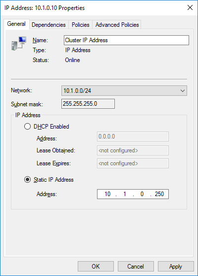
114. In the IP Address: 10.1.0.20x Properties dialog box:
- In the General tab, under the IP Address section, select the Static IP address option button and type 10.1.0.250 in the Address text box. The IP address can have any value within the range of the Production subnet of the Public-Azure-East Azure VNet so long as it is available.
- Click OK. This will assign the new static IP address to the WSFC virtual host name/client access point.
115. In the Cluster Core Resources section, select the name of the WSFC virtual host name/client access point.
116. Right-click and select Bring Online. This will bring the WSFC virtual host name/client access point online together with the newly assigned static IP address.
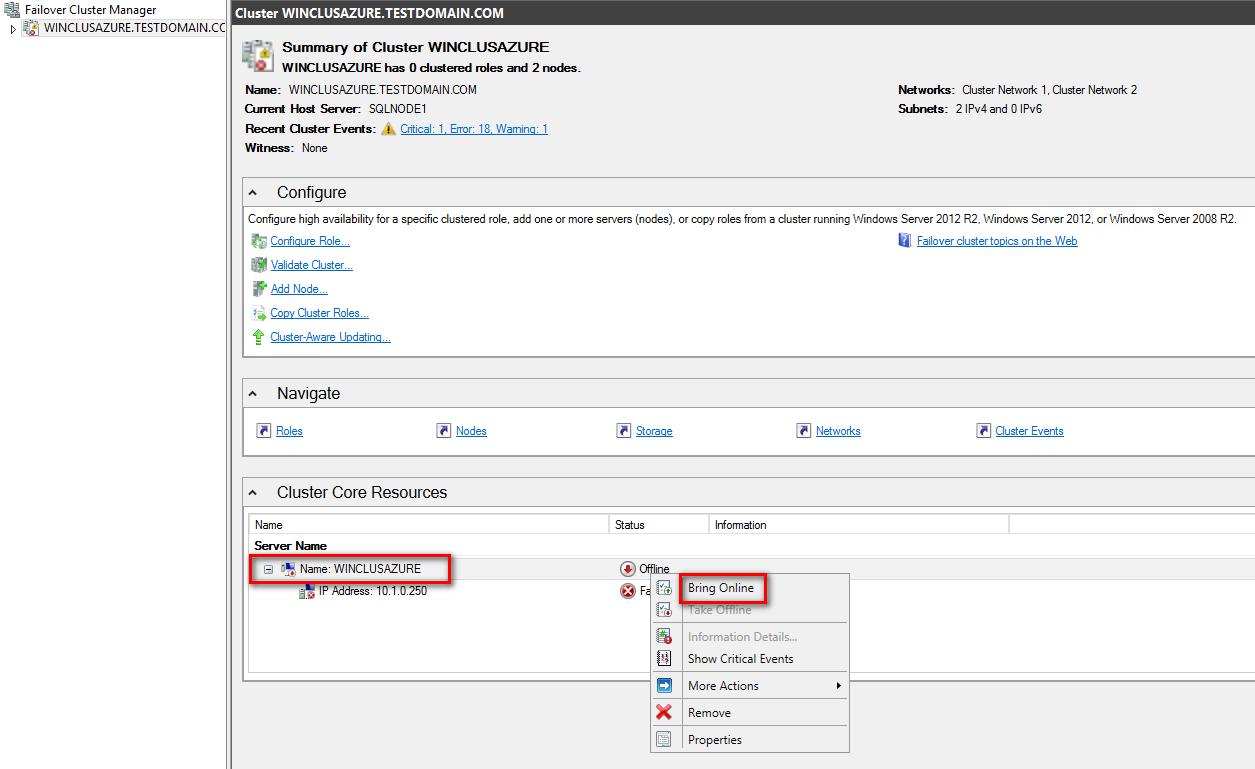
Because the WSFC virtual host name/client access point now has a different IP address from the ones used by the virtual machines, all of the services on both of the virtual machines will now become available.
Creating the Windows Server 2016 Failover Cluster Using PowerShell
Alternatively, it is possible to create the Failover Cluster through PowerShell and avoid reconfiguring the networks in the failover cluster as performed in previous steps. The script for creating the failover cluster is provided below. Update the script with the names of the hosts (the virtual machine names) and an available IP address from the Azure VNET:
New-Cluster -Name <FailoverCluster-Name> -Node ("<node1>","<node2>") –StaticAddress <n.n.n.n> -NoStorage
Configuring Cluster Quorum Settings
For WSFC to maintain quorum, another vote must be added in the form of a file share witness. This section, describes how to configure the cluster quorum setting using a file share witness. A file share must be created on the domain controller for this purpose and the Windows Failover Cluster virtual server must be granted Read/Write permissions to it.

NOTE: These steps can be performed on any of the servers that will act as WSFC nodes. The steps below are performed on SQLNODE1.
117. Open the Failover Cluster Manager console in the Administrator mode
118. Select the name of the WSFC virtual host name/client access point.
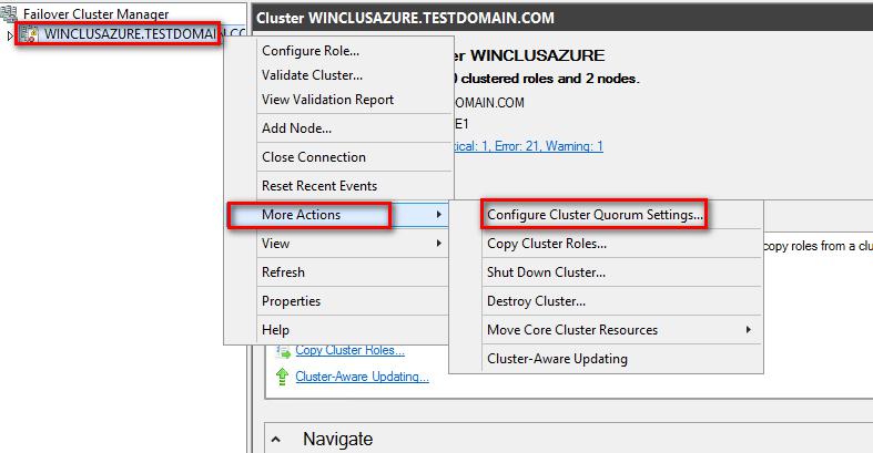
119. Right-click the cluster, select More Actions, and click Configure Cluster Quorum Settings… This will open up the Configure Cluster Quorum Wizard
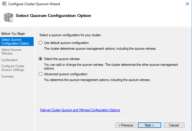
120. In the Select Quorum Configuration dialog box, choose the Select the quorum witness option. Click Next.
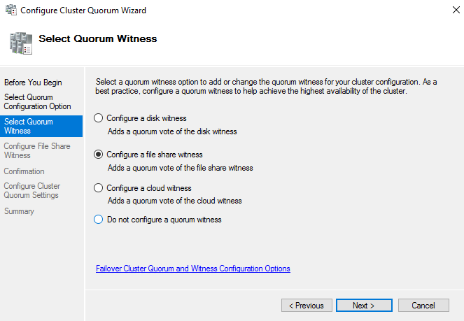
121. In the Select Quorum Witness dialog box, choose the Configure a file share witness option. Click Next.
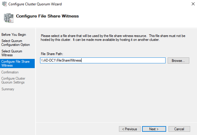
122. In the Configure File Share Witness dialog box, type the path of the file share witness. Click Next.
123. In the Confirmation dialog box, review the configuration settings and click Next.
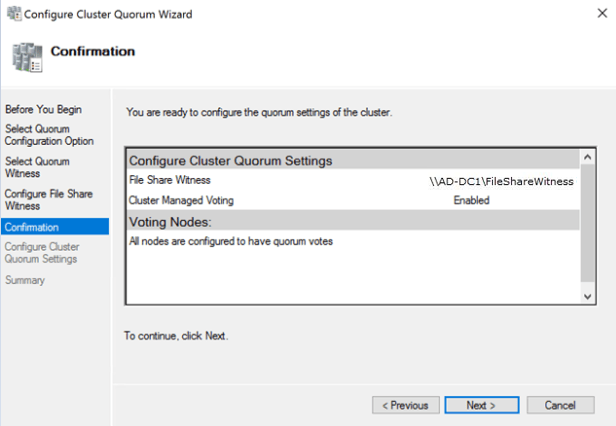
124. In the Summary dialog box, verify that the entire configuration is successful.
Installing SQL Server 2017 on a Failover Cluster
This section describes how to install SQL Server 2017 failover clustered default instance on a Windows Server Failover Cluster in Microsoft Azure. The installation process will be performed on the first node of our cluster, SQLNODE1.
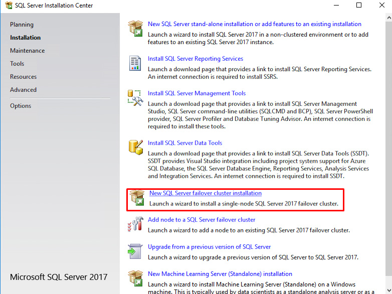
125. Run setup.exe from the SQL Server 2017 installation media to launch SQL Server Installation Center. Click on the Installation link on the left side.
126. Click the New SQL Server failover cluster installation link. This will run the SQL Server 2017 Setup wizard
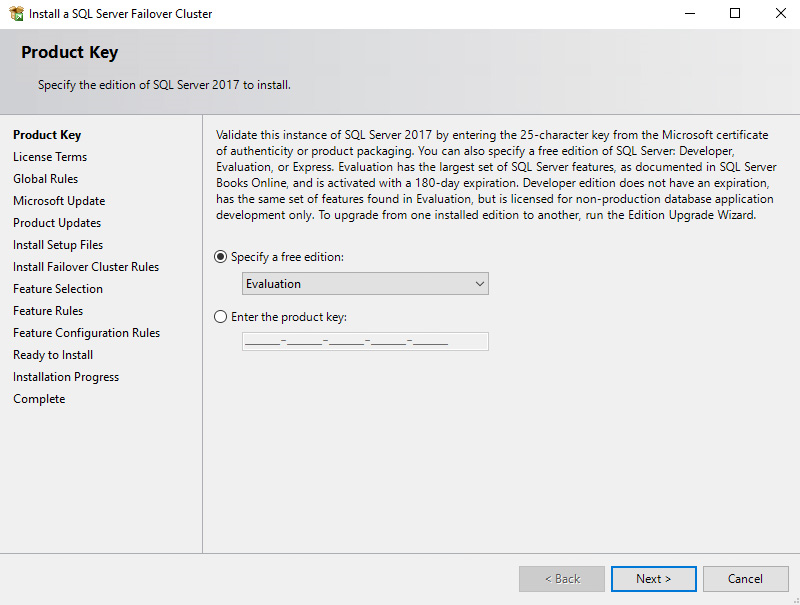
127. In the Product Key dialog box, enter the product key received with the installation media and click Next.
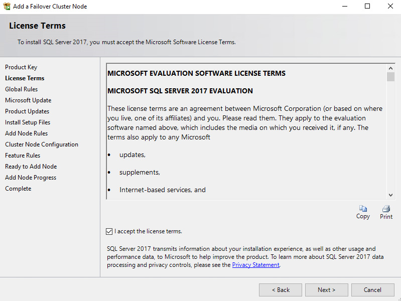
128. In the License Terms dialog box, click the I accept the license terms check box and click Next.
129. In the Global Rules dialog box, validate that the checks return successful results and click Next.

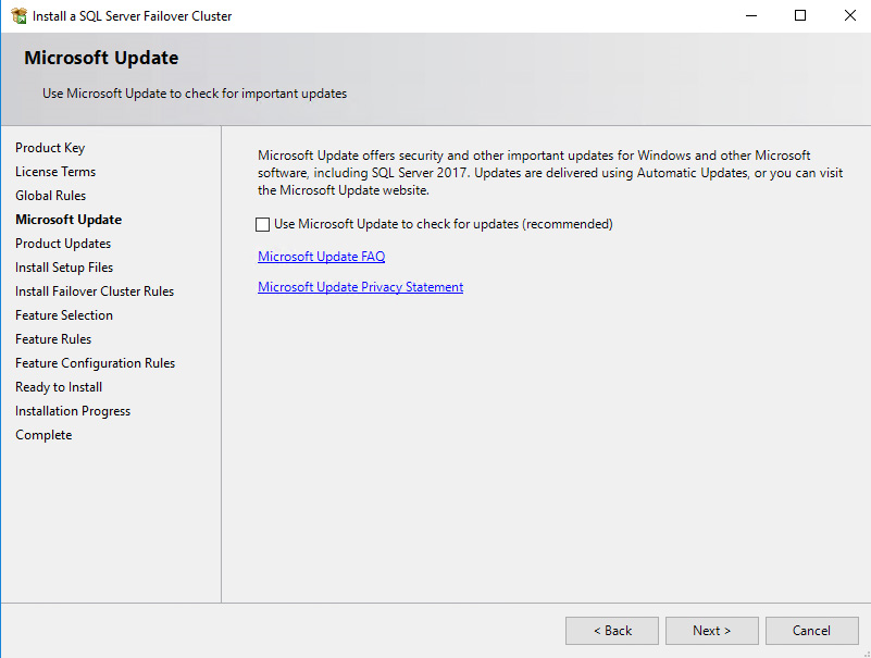
130. In the Microsoft Update dialog box, click Next.
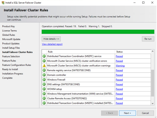
131. In the Install Failover Cluster Rules dialog box, validate that the checks return successful results. If the checks returned a few warnings, make sure to fix them before proceeding with the installation. Click Next.
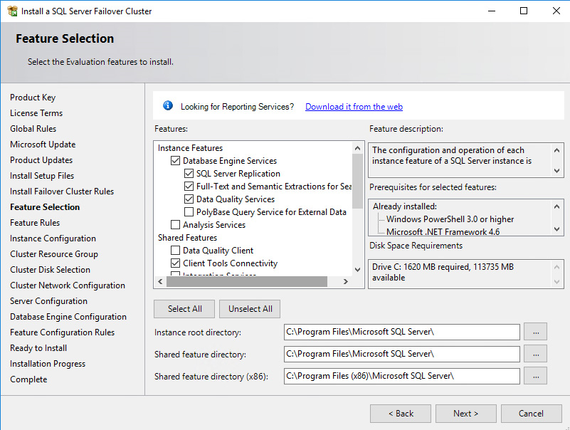
132. In the Feature Selection dialog box, select the following components – Database Engine Services and Management Tools. Click Next.
133. In the Feature Rules dialog box, verify that all the rules have passed. If the rules returned a few warnings, make sure to fix them before proceeding with the installation.
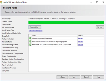
Click Next.
134. In the Instance Configuration dialog box, enter the following details:
- SQL Server Network Name: Type name of cluster
- Instance ID: MSSQLSERVER
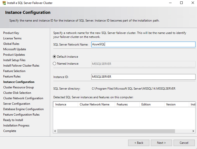
Click Next.
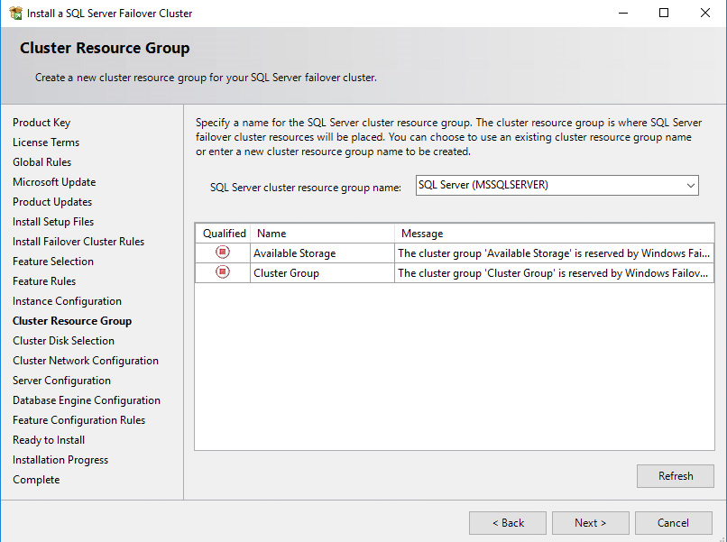
135. In the Cluster Resource Group dialog box, check the resources available on the Windows Server Failover Cluster. This displays that a new Resource Group will be created on the cluster for the SQL Server instance. To specify the SQL Server cluster resource group name, use the drop-down box to specify an existing group to use or type the name of a new group to create it. Accept all the defaults and click Next.
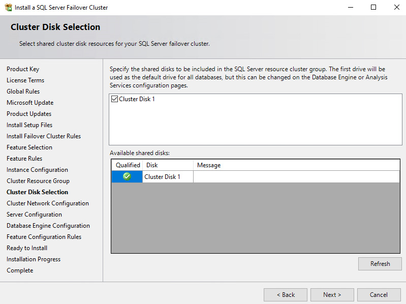
136. In the Cluster Disk Selection dialog box, select the available disk groups that are on the cluster for SQL Server 2017 to use. Click Next.
137. In the Cluster Network Configuration dialog box, enter the virtual IP address that the SQL Server 2017 failover clustered instance will use. Select the checkbox beside the IPv4 column as a static IP addresses that will be used instead of DHCP-assigned. Click Next.
- Address: 10.1.0.180 (similar to virtual IP address for the WSFC virtual host name/client access point, the IP address can have any value within the range of the Production subnet of the Public-Azure-East Azure VNet so long as it is available).
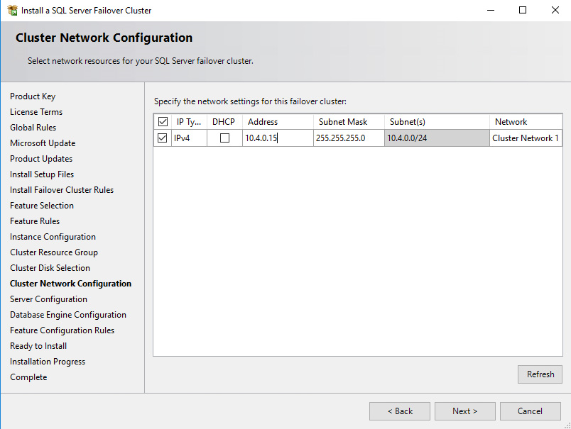
NOTE: The network adapter settings that will be displayed in this dialog box will depend on how the cluster network adapters are configured. Be sure to configure the Heartbeat-iSCSI network adapters with the Do not allow cluster network communication on this network option.
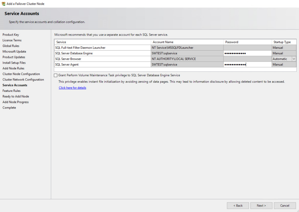
138. In the Server Configuration dialog box, use the following credentials for the SQL Server service accounts in the Service Accounts tab. Make sure that both the SQL Server Agent and SQL Server Database Engine services have a Startup Type of Manual. The Windows Server Failover Cluster will stop and start the service. Also, set the Collation property for the instance according to your application requirements.
- SQL Server Agent: TESTDOMAIN\sqlservice
- SQL Server Database Engine: TESTDOMAIN\sqlservice
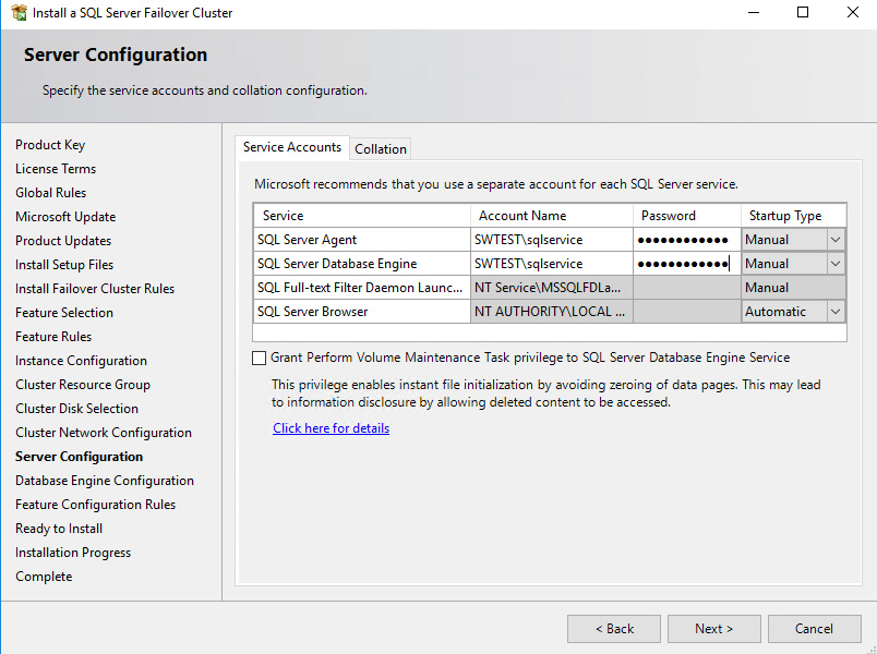
Click Next.
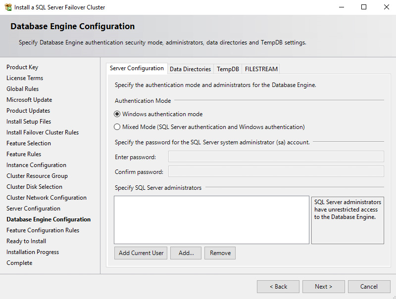
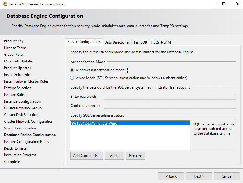
139. In the Database Engine Configuration dialog box, select the appropriate Authentication Mode in the Server Authentication tab. If you want to add the currently logged on user to as a part of the SQL Server administrators group, click the Add Current User button. Otherwise, you can add the appropriate domain accounts or security groups.
140. In the Data Directories tab, enter the following data based on the available clustered disks:
- Data root directory: J:\
- User database directory: J:\MSSQL12.MSSQLSERVER\MSSQL\Data
- User database log directory: L:\MSSQL12.MSSQLSERVER\MSSQL\Data
- Temp DB directory: J:\MSSQL12.MSSQLSERVER\MSSQL\Data
- Temp DB log directory: L:\MSSQL12.MSSQLSERVER\MSSQL\Data
- Backup directory: J:\MSSQL12.MSSQLSERVER\MSSQL\Backup
NOTE: The option to store the tempdb database on a local drive instead of a clustered drive has been introduced in SQL Server 2012. For WSFC in Microsoft Azure, it is recommended to store the tempdb database on a local drive instead of the replicated storage. Make sure that all of the nodes in the cluster contain the same directory structure and that the SQL Server service account has read/write permissions to the folders.
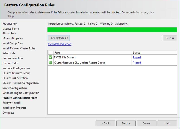
141. In the Feature Configuration Rules dialog box, click Next.
142. In the Ready to Install dialog box, verify that all configurations are correct. Click Next.
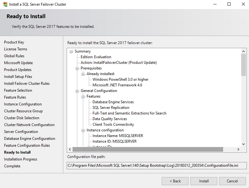
143. Once the installation finishes, in the Complete dialog box, click Close.

Adding a node to a SQL Server 2017 Failover Cluster
This section describes how to add a node to the SQL Server 2017 failover clustered default instance on a Windows Server Failover Cluster. The installation process will be performed on the second node of the cluster: SQLNODE2.
To add a node to a SQL Server 2017 failover clustered instance:
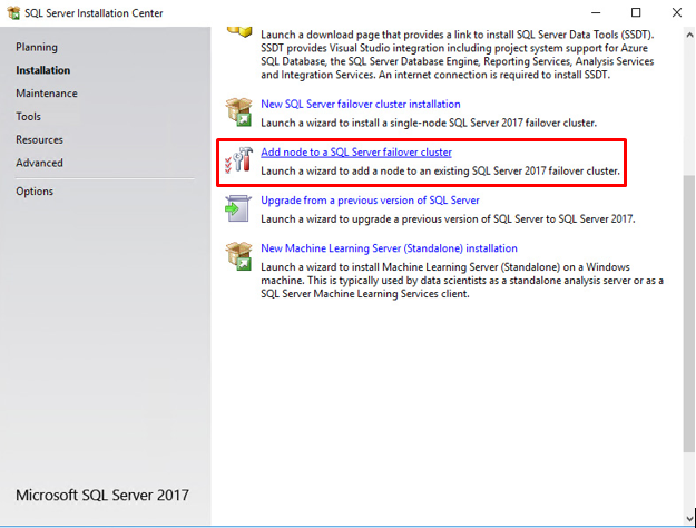
144. Run setup.exe from the installation media to launch SQL Server Installation Center.
145. Click on the Installation tab on the left side. Click the Add node to a SQL Server failover cluster link. This will run the SQL Server 2017 Setup wizard.
146. In the Product Key dialog box, enter the product key received with the installation media and click Next.
147. In the License Terms dialog box, select the I accept the license terms check box and click Next.
148. In the Global Rules dialog box, validate that the checks return successful results and click Next.
149. In the Microsoft Update dialog box, click Next.
150. In the Add Node Rules dialog box, validate that the checks return successful results. If the checks returned a few warnings, make sure to fix them before proceeding with the installation. Click Next.
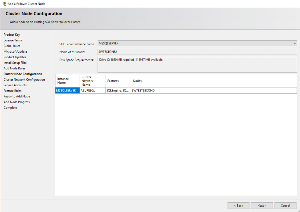
151. In the Cluster Node Configuration dialog box, validate that the information for the existing SQL Server 2017 failover clustered instance is correct. Click Next.
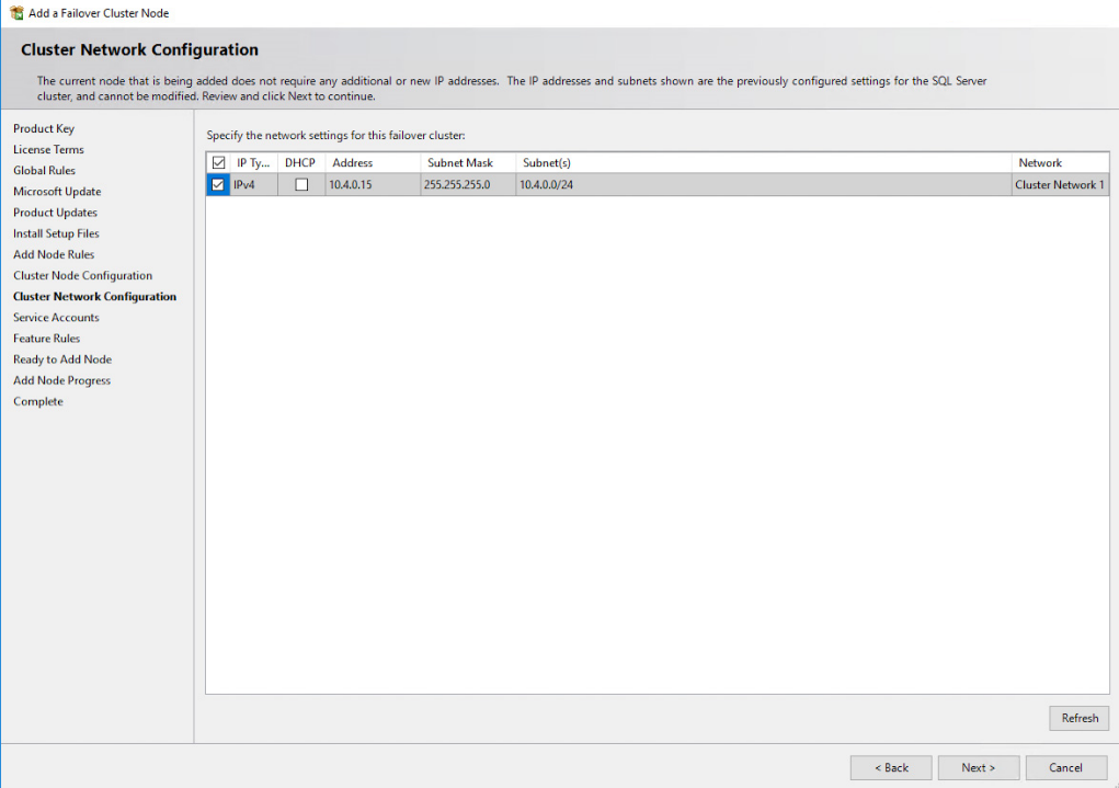
152. In the Cluster Network Configuration dialog box, review the configuration of the SQL Server failover clustered instance. Click Next.
153. In the Service Accounts dialog box, verify that the information corresponds to the information used to configure the first node. Provide the appropriate password for the SQL Server service accounts. Click Next.
154. In the Feature Rules dialog box, click Next.
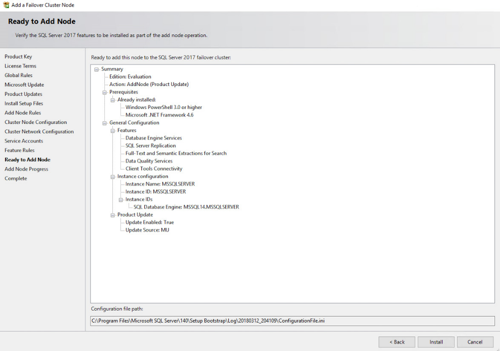
155. In the Ready to Add Node dialog box, verify that all configurations are correct and click Install.
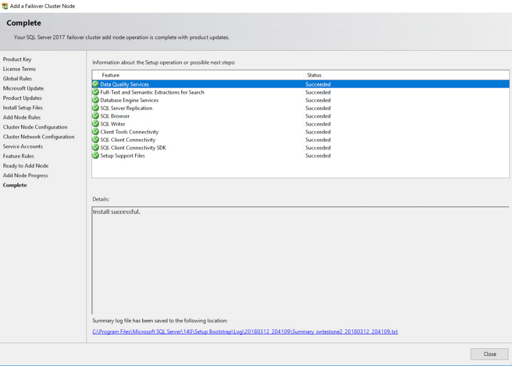
156. Once the installation finishes, in the Complete dialog box, click Close. This concludes adding a node to a SQL Server 2017 Failover Cluster.
NOTE: When storing the tempdb database on a local drive instead of a replicated drive, make sure that:
- The same drive letter and folder structure exists on all of the nodes in the cluster
- The SQL Server service account has the appropriate permissions on the folder where tempdb will be created
Creating an Azure Internal Load Balancer
This section describes how to create an Azure internal load balancer to forward traffic from the Azure VNet to the virtual machines. Client applications that are connected to the SQL Server failover clustered instance should be connected to the internal load balancer instead of being connected directly to the virtual IP address. An Azure internal load balancer consists of the Azure cloud service IP address and a port number that the client applications will be connected to.
The following tasks will be performed using Windows PowerShell with the Azure PowerShell modules.
NOTE: The process of creating an Azure load balancer will be different depending on where the client applications will access the SQL Server failover clustered instance. This example assumes that the client applications will also be running on Microsoft Azure but reside on a different Azure cloud service than the one containing the SQL Server failover clustered instance. A more detailed coverage of Azure load balancers is described in Load Balancing for Azure Infrastructure Services.
Use the example PowerShell script below to create the Azure internal load balancer. Parameters used in the example are commented on how they are used. All code is written as single-lines. Format appropriately in code/script editor.
#Add the internal load balancer to the Azure cloud service.

$cloudSvcName = "SQLFailover-poc"#the name of the cloud service that contains the VM nodes in the WSFC

$ILBName = "AZURE-ILB" #name for the new Azure internal load balancer that we will create

$subnetName = "Production" #name of the subnet that the VMs use in the Azure VNet for production traffic

$ILBStaticIP = "10.1.0.180" #static IP address for the Azure internal load balancer in the subnet could be the same as the SQL Server FCI virtual IP address

#Add Azure internal load balancer

Add-AzureInternalLoadBalancer -InternalLoadBalancerName $ILBName -SubnetName $subnetName -serviceName $cloudSvcName -StaticVNetIPAddress $ILBStaticIP

#Configure the load balanced endpoint for each node using Azure internal load balancer

$VMNodes = "SQLNODE1", “SQLNODE2"#hostnames of VM nodes in the WSFC, separated by commas

$endpointName = "SQLCLUSAZURE" #name of the endpoint for the SQL Server FCI, ideally same as the SQL Server FCI

$endpointPort = "1433" #port number to use for the endpoint for SQL Server FCI

$endpointName_LB = "AZUREILBEP" #name of a Azure internal load balancer endpoint

#(this is different from the name of the Azure internal load balancer)

#Add Azure internal load balancer endpoint with port 1433 and probe port 59999 to each node.

#The probe port is a random port number that the Azure internal load balancer uses to ensure that the members of the #load-balanced set are available

#Configure a load balanced endpoint for each node in the SQL Server FCI, with direct server return enabled

forEach ($node in $VMNodes)

{

Get-AzureVM -serviceName $cloudSvcName -Name $node | Add-AzureEndpoint - Name $EndpointName -LBSetName $endpointName_LB -Protocol tcp -LocalPort $EndpointPort -PublicPort $EndpointPort -ProbePort 59999 -ProbeProtocol tcp -ProbeIntervalInSeconds 10 -InternalLoadBalancerName $ILBName - DirectServerReturn $true | Update-AzureVM

}
NOTE: The endpoint port number of the Azure internal load balancer (1433), the probe port number (59999), and port number 1434 (used by the SQL Browser service) should be opened on the Windows Firewall of both the WSFC nodes.
Updating the SQL Server Failover Clustered Instance Virtual Network Name
This section describes how to update the SQL Server Failover Clustered Instance virtual network name and assign the IP address of the Azure internal load balancer together with the probe port number. The cluster resource group will be turned offline and back up online for the changes to take effect. Windows PowerShell will be used an instrument for performing the required steps.
NOTE: These steps can be performed on any of the servers that will act as WSFC nodes. The steps below are performed on SQLNODE1.
Use the example PowerShell script below to create the Azure internal load balancer. Parameters used in the example are commented on how they are used. All code is written as single-lines. Format appropriately in code/script editor.
# Define variables

$clusterNetworkName = "Cluster Network 1" #the cluster network name for the SQL Server FCI

#use Get-ClusterNetwork or Failover Cluster Manager to find the appropriate name

$IPResourceName = “SQL IP Address 1 (SQLCLUSAZURE)" #the IP Address resource name of the SQL Server FCI

#use Get-clusterresource | where {$_.resourcetype -eq "IP Address"} for Failover Cluster Manager to find the appropriate name

$ILBStaticIP = “10.1.0.180” #the IP Address of the Azure internal load balancer

#Update the WSFC resource parameters of SQL Server FCI IP address to work with the Azure internal load balancer

Get-ClusterResource $IPResourceName | Set-ClusterParameter -Multiple @{"Address"="$ILBStaticIP";"ProbePort"="59999";SubnetMask="255.255.255.2 55";"Network"="$clusterNetworkName";"OverrideAddressMatch"=1;"EnableDhcp "=0}

#Take the cluster resource offline and the cluster resource group back online for the changes to take effect

Stop-ClusterResource "SQL IP Address 1 (SQLCLUSAZURE)"

Start-ClusterGroup "SQL Server (MSSQLSERVER)"
Testing Application Connectivity
This section describes how to test application connectivity for SQL Server 2017 failover clustered instance running on Microsoft Azure. SQL Server 2017 Management Studio will be used to perform the required tasks.
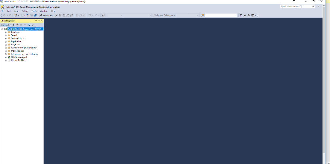
NOTE: For client connectivity using the Azure internal load balancer, client connections to the SQL Server failover clustered instance virtual network name must come from VMs that reside in a different Azure cloud service than the one hosting the WSFC nodes. In the example below, the virtual machine named swtestone2 is on the sqlfailover.westeurope.cloudapp.azure.com cloud service. However, it is using the Production subnet of the Public-Azure-East Azure VNet, configured with an internal IP address of 10.1.0.211 and uses AD-DC1 as the internal DNS server.

To connect to the SQL Server failover clustered instance, use the SQL Server virtual network name in SQL Server Management Studio.

CONCLUSION
Having performed all the steps described above, a 2-node Windows Server 2016 Failover Cluster has been configured. The Failover Cluster will host a SQL Server failover clustered instance (FCI) on Azure virtual machines, which makes the setup 99.9% available since it is located in a cloud.
