


Disaster recovery (DR) is a must-have for any serious IT environment. Imagine your primary data center goes dark – how quickly can you bring everything up at a secondary site? VMware Site Recovery Manager (SRM) 9.0, now rebranded as VMware Live Site Recovery, is the tool designed for this scenario. It automates and orchestrates virtual machine failover between sites, minimizing downtime and simplifying recovery workflows. In this deep dive, we’ll walk through setting up a two-site DR solution with SRM 9.0 step by step.
SRM 9.0 Topologies and Best Practices
VMware SRM supports a few deployment topologies for pairing protected and recovery sites:
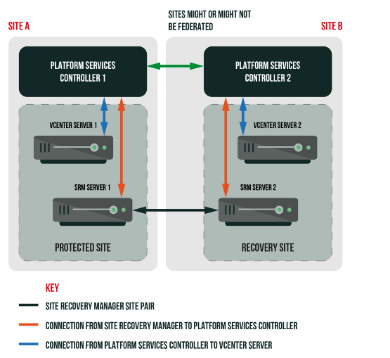
- Standard Two-Site Configuration: This is the most common setup. You have one vCenter Server, with an associated SRM instance, at the primary site and a second vCenter+SRM at the recovery site. These two sites can either share the same Single Sign-On domain, e.g. linked via Enhanced Linked Mode, or use separate SSO domains. Using a common SSO domain allows unified management, but using separate SSO domains is generally recommended for true DR. If all vCenters share one SSO domain and that service fails, SRM cannot function – separate SSO domains ensure each site’s vCenter/SRM can operate independently in a disaster.
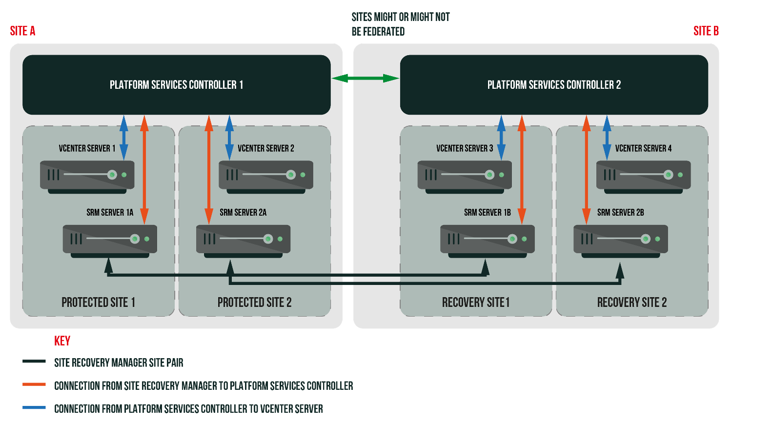
- Multiple vCenters per Site: A less common scenario is having multiple vCenter Servers at one site (each with its own SRM) protecting to one or multiple vCenters at the other site. SRM can handle these more complex pairings, including many-to-one or one-to-many, even mixing on-premises sites with cloud-based VMware sites, but those advanced topologies are beyond our scope here. In this guide, we’ll focus on the straightforward two-site configuration, as it’s the typical DR design for most organizations.
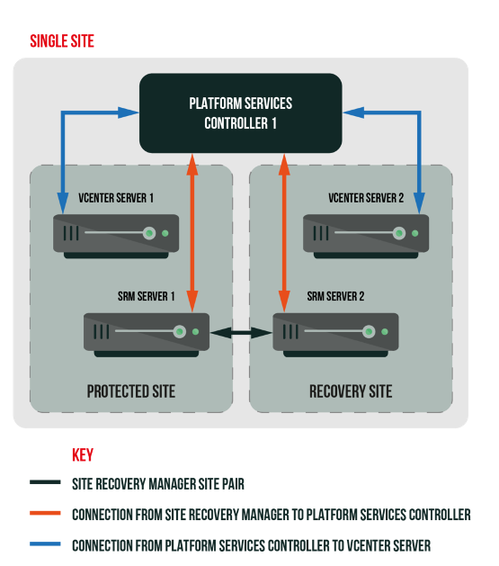
- “Single-Site” (Not Recommended): In theory, you could install SRM with both vCenter instances in one SSO domain or even one physical location, but this defeats the purpose of true disaster recovery. If a single SSO domain or data center is down, both “sites” could be affected. Always design your DR with physical and logical separation in mind.
Key takeaway: Aim for two independent sites – each with its own vCenter, PSC/SSO, and SRM. This ensures that if the primary site is lost, the recovery site’s vCenter and SRM are still available to orchestrate the failover.
Pairing the Sites with SRM
Once your two SRM servers (one at each site) are installed and registered with their respective vCenter Servers, the first step is to pair them in the vSphere Client. SRM 9.0 is fully integrated into the vSphere HTML5 client as a plugin, so all operations happen there – no separate Flash or Flex interface as in the past.
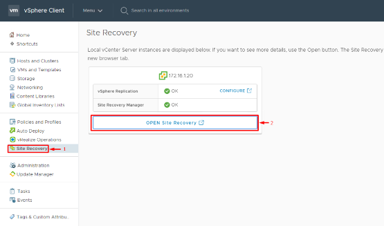
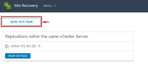
1. Open the Site Recovery interface: In the vSphere Client (HTML5 UI), navigate to Site Recovery in the menu and click Open Site Recovery. This will launch the SRM plugin’s dashboard view, where you can manage site pairs, replications, and recovery plans.
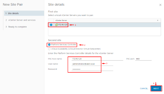
2. Start a New Site Pair: In the Site Recovery (SRM) home screen, click New Site Pair to launch the pairing wizard. Select your local site’s vCenter Server from the drop-down. For the remote site, you’ll need to provide the address of the vCenter Server at your DR location, along with administrative credentials if prompted.
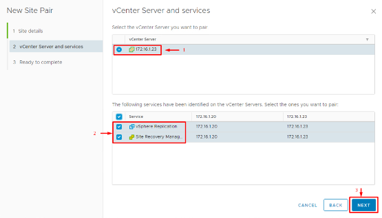
3. Select Services to Pair: The wizard will ask which services to connect. Ensure that both Site Recovery Manager and vSphere Replication are selected for pairing. (vSphere Replication is the built-in replication mechanism for VMs, which we’ll use in this guide. If you plan to use array-based replication only, you’d still pair SRM instances here, and set up arrays separately.)
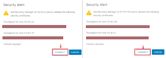
4. Certificate Verification: You may be prompted to trust the SSL certificates of the remote vCenter/SRM appliance. Verify the thumbprints and click Finish or OK to establish the trust. This is a one-time step to allow secure communication between the two SRM instances.
After completing the wizard, you should see the new site pair in the SRM dashboard. Both sites will be listed (Primary and Recovery), and their status should show as Connected.
On the Summary tab of the site pair, check that no errors are reported. Congratulations – at this point the two sites “know” about each other, and you’re ready to configure how VMs will map and replicate between them.
Configuring Inventory Mappings and Placeholder Datastores
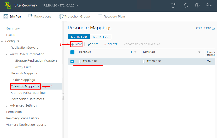
With the sites paired, the next step is to tell SRM how to map resources from the protected site to the recovery site. This ensures that when a failover happens, each VM finds an appropriate home (compute, storage, network) on the DR side. In the Site Recovery interface under your site pair, find Inventory Mappings and configure the following:
Resource Mappings: Map your compute containers (clusters, resource pools, VM folders) from the primary site to corresponding ones at the recovery site. This way, a VM running in Cluster A / Resource Pool X at primary can be placed in an equivalent cluster/pool at DR.
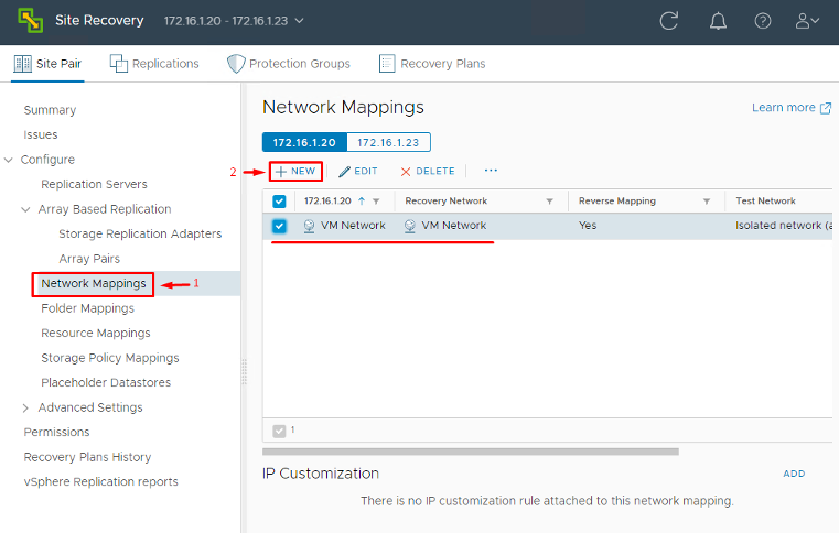
- Network Mappings: Map networks (Port Groups or distributed virtual portgroups) between sites. For example, the VM network “Production-Net” at primary might map to “DR-Production-Net” at the recovery site. This mapping means that during recovery, SRM will connect each VM’s NIC to the correct recovery network automatically.
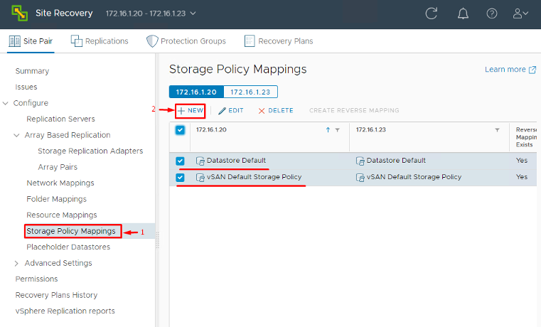
- Storage Policy Mappings: If you use vSphere Storage Policies (e.g. a policy that indicates “Tier 1 Storage”), map those policies to comparable ones on the DR site. This is mostly relevant if you have policy-based storage management; it tells SRM how to translate a VM’s storage profile upon recovery.
These mappings ensure that when a protected VM is recovered, SRM can translate its original settings to the DR site’s environment without manual intervention. Mapping everything (folders, compute, network and storage policies) in advance saves you from having to set these per-VM later on.
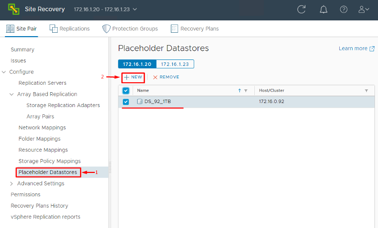
- Placeholder Datastores: Next, configure a placeholder datastore on each site. A placeholder datastore is a datastore (it can be a small VMFS volume or NFS share) where SRM will store placeholder VM files for each protected VM. These placeholder VMs are basically empty shell VM entries that sit in the recovery site’s vCenter inventory to represent the protected VMs. They consume minimal space, just a VMX configuration file and a few kilobytes, but are crucial: they reserve the VM’s identity (UUID, MAC, etc.) at the recovery site. Configure at least one placeholder datastore per site (often one per cluster or whatever makes organizational sense). In the SRM interface, you’ll find a section to set the Placeholder Datastore – choose an appropriate datastore that is NOT used for actual replication data. Remember, during a failover, SRM will “swap in” the real replicated VMDKs and data into this placeholder VM. Without a placeholder datastore configured, SRM cannot create those placeholder VMs.
Finally, ensure your replication infrastructure is in place. If you plan to use array-based replication, install and register the Storage Replication Adapters (SRAs) for your storage arrays on both SRM servers and verify that SRM can see the replicated LUNs/volumes. If you’re using vSphere Replication (VR) (as we do in this guide), make sure the vSphere Replication appliance is deployed at each site and paired. The SRM plugin will show the status of vSphere Replication once connected. At this stage, you should have pairing and mappings done, and a replication method in place (even if the actual per-VM replications aren’t configured yet). Now we can proceed to set up the VM replications.
Setting Up VM Replication (using vSphere Replication)
SRM works with two replication options: storage-array replication (with vendor SRAs) or vSphere Replication (a hypervisor-level replication for VMs). We’ll use vSphere Replication in this walkthrough, since it’s versatile and included with most vSphere editions. (If you were using array replication, skip this section and ensure your LUNs are replicating; then you’d create protection groups based on those storage devices.)
To configure replication for your VMs using vSphere Replication:
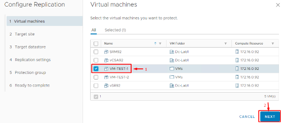
1. Start the Replication Wizard: In the Site Recovery UI, go to Replications and click New (or Configure Replication). This opens a wizard that will guide you through selecting VMs and configuring their replication settings.

2. Select VMs to Replicate: Choose the source VMs (on the protected site) that you want to protect. You can multi-select several VMs or do them one by one. Each VM you configure here will get a replica on the DR site.
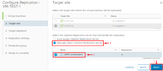
3. Choose Target Site and VR Server: Next, specify the target (recovery) site for replication. If you have deployed additional vSphere Replication Server instances (for load balancing), you can select which VR server will handle this VM’s replication. Otherwise, use the default.
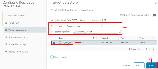
4. Specify Target Datastore: Choose a datastore at the recovery site where the VM’s replicated data will be stored. This should be a datastore with enough capacity to hold the VM’s VMDKs. You can optionally pick a different disk format (same format as source or thin-provisioned) and assign a storage policy if applicable.
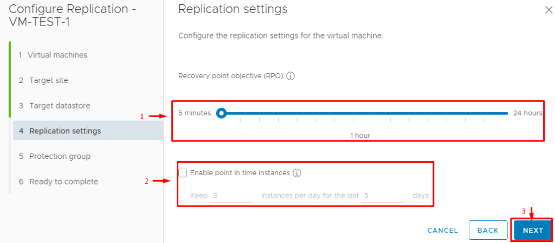
5. Configure RPO and Retention: Set the Recovery Point Objective (RPO) for this VM. RPO is how fresh you need the replicated data to be. With vSphere Replication, you can go as low as 5 minutes or as high as 24 hours for RPO, configured per VM. A lower RPO means more frequent replication (and higher network usage) but less data loss in a disaster. You can also enable “point in time” snapshots and specify how many recovery points to retain. vSphere Replication supports up to 24 recovery point snapshots per VM, allowing you to revert to an earlier version of the VM if needed (useful in cases of ransomware or corruption where the latest state might not be desirable).
6. Review and Start Replication: Review the summary of your settings and finish the wizard. The chosen VMs will begin an initial full sync to the target site. Depending on the size of the VM and network bandwidth, this initial replication can take some time. You can monitor progress in the Replications view.
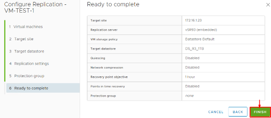
A couple of things to note after setting up replication: The wizard allows you to set the replication direction as well. Normally, we configure replication from Primary (protected) → Recovery site. SRM 9.0 also supports configuring reverse replication after a failover (for failback scenarios), but that is typically done through the Reprotect process post-failover (we’ll touch on that later). For now, you should see your VMs listed under Outgoing Replications at the protected site and Incoming Replications at the recovery site, with a status like “Initial Full Sync” and eventually “OK”. Once a VM shows as Ready (fully replicated), we can add it to an SRM Protection Group.
(If you were using array-based replication, you wouldn’t use the above wizard. Instead, after your storage array replicates the LUNs and the SRAs are configured, SRM would detect those devices. You would then create array-based protection groups that encompass the VMs on those LUNs. The rest of the process – creating recovery plans, etc. – is similar, though the interface differs when selecting datastore groups instead of individual VMs.)
Creating Protection Groups in SRM
A Protection Group is a logical grouping of VMs that will fail over together. Think of it as the set of VMs that share a common recovery plan. Often, you group VMs by application or by datastore. For example, all VMs for the payroll application might be one protection group, or if using array replication, all VMs on a specific replicated LUN become a group. In SRM 9.0, each protection group can include up to 1,500 VMs, a significant increase that allows greater scalability. (This high limit is useful in large environments, though it’s still wise to group VMs logically rather than make one giant group.)
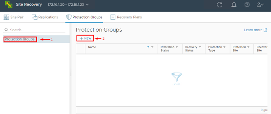
To create a Protection Group in SRM 9.0:
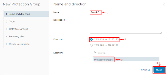
1. Start New Protection Group Wizard: In the Site Recovery UI, go to Protection Groups and click New. Choose the direction of protection. For our example, select Primary → Recovery, meaning the VMs at the primary site will fail over to the recovery site. Give the group a clear name (e.g., “Sales-App-PG” or “All-Prod-VMs-PG”) so you can identify it later.
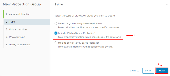
2. Select Protection Type: SRM will ask what type of protection group to create. This depends on your replication type. If you are using vSphere Replication, choose Individual VMs (each VM is protected via VR). If you were using array replication, you might see an option for Datastore groups (grouping VMs by replicated datastore). For our case, choose Individual VMs.
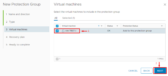
3. Add VMs to the Group: The wizard will list VMs that are available to protect. For vSphere Replication, this list shows all VMs for which replication is configured and ready. Select the VMs you want to include in this protection group. You can add multiple VMs now, and you can always add or remove VMs from the group later as needed. (If a VM wasn’t set up for replication yet, SRM may even offer to set it up now, but it’s best to have done that in the previous step.)
4. Finish the Wizard: Confirm the settings and complete the creation. SRM will now create placeholder VMs on the recovery site for each protected VM you added. These placeholders (stored on that placeholder datastore you configured earlier) act as stubs in the recovery vCenter’s inventory, representing the protected VMs. As soon as the PG is created, you can look in the recovery site vCenter inventory (in the VMs and Templates view) and you should see the placeholder VMs (often with a grayed-out icon). This confirms that the VMs are officially “protected” by SRM.
When you add VMs to a protection group, SRM takes care of provisioning those placeholder VMs with all the correct mappings and settings you defined earlier. As one VMware guide explains, SRM automatically “creates placeholder VMs in the recovery site with the right mappings” for network, folder, resource pool, etc., as part of the protection process. This saves you a ton of manual work and ensures consistency.
Now, during the Protection Group creation, you might be prompted to verify or adjust certain per-VM settings (especially if you didn’t configure Inventory Mappings or have some exceptional cases). Here are a few things you can customize for each VM in the group:
- Recovery VM location: You can override the default resource pool or folder mapping for a specific VM if needed.
- Recovery Network: If one particular VM needs to connect to a different network at failover (not using the global mapping), you can set that.
- VM Startup Priority: SRM allows you to specify the order in which VMs power on during recovery. For instance, you may want database servers to start before application servers, which start before web servers. You can set High, Normal, or Low priority, or even create custom priority groups in the Recovery Plan (next section).
- Guest Customization: If your failover site uses a different IP scheme, you can configure IP customization for the VM. SRM can integrate with VMware Tools to set a new IP address, subnet, gateway, DNS, etc., on the recovered VM. This is crucial if you can’t stretch Layer-2 networks between sites and need to change IPs on failover.
- Scripts and Hooks: SRM allows running custom scripts – e.g., pre-power-off scripts on the protected site VMs (to gracefully shut them down or sync data), and post-power-on scripts on recovery site VMs (to verify app status, send alerts, etc.). You can also set prompt messages or timeouts. These are optional advanced settings that help handle application-specific logic during failover.
It’s okay if you skip some of these customizations during initial setup; you can always edit the protection group and VM settings later. After finishing the PG wizard, you should see your new Protection Group listed, showing the number of VMs it contains and a status (e.g., “Protected” or “Not Configured” if something’s amiss). At this point, those VMs are protected by SRM: their states are being replicated, and we have placeholders ready. But we haven’t defined how to fail them over—that’s where Recovery Plans come in.
Building a Recovery Plan (The Failover Runbook)
A Recovery Plan in SRM is essentially an automated runbook that orchestrates the failover process for one or more protection groups. If a Protection Group is a container of VMs, the Recovery Plan is the actual sequence of steps to recover those containers. The Recovery Plan controls things like: the order in which protection groups (and the VMs in them) are recovered, network handling, waits and prompts, and any custom actions.
You can have multiple recovery plans for different scenarios. For example, you might have an “All Production Recovery” plan that includes all PGs, and another plan just for a specific application (containing only that app’s PG). A Protection Group can be included in more than one plan (useful if you want both a full-site disaster plan and a subset plan for planned migrations of one app).
To create a Recovery Plan:
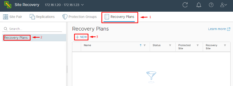
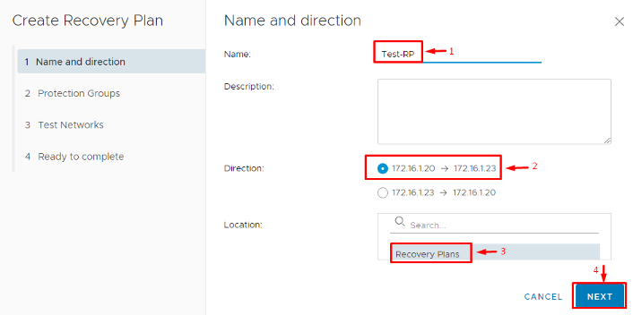
1. Launch the New Plan Wizard: In the SRM interface, go to Recovery Plans and click New. Give the plan a descriptive name (e.g., “DR Plan – Full Site” or “Payroll-App-DR-Plan”) and select the direction of recovery (e.g., Primary → Recovery site). Typically, this matches the direction of your protection groups.
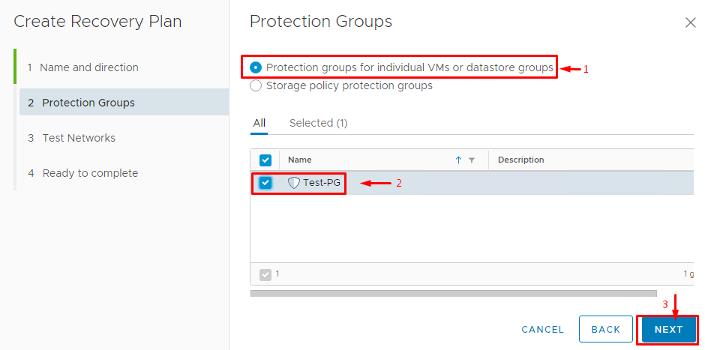
2. Select Protection Groups: Choose one or more Protection Groups to include in this plan. You might include all your PGs for a complete site failover plan, or just one for a targeted plan. Add the relevant groups now.
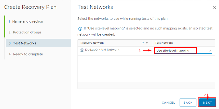
3. Configure Test Network: You’ll be asked to select a Test Network for this plan. The test network is an isolated network at the recovery site that SRM will use when you perform a Test recovery. You should have a dedicated VLAN or port group at the DR site designated for testing (with no routing to production). Map the primary site networks to this isolated test network. This way, when you test the plan, VMs come up in a sandbox network and don’t disrupt your real network. For example, if production network “Corp-LAN” is mapped to “Corp-LAN-Isolated” (a bubble network) during test, the VMs will connect there during test failover. (During an actual recovery, SRM will use the normal mapped network instead.)
Note: If you haven’t created a dummy isolated network yet, now’s a good time to do so in vCenter. It can simply be a port group with no uplinks or a VLAN not routed anywhere.
4. Review and Create: Finish the wizard. The new Recovery Plan will appear in the list.
At creation, the Recovery Plan is basically a template. You can click on a plan to see its Steps. SRM generates a default set of steps for you, which include actions like powering off VMs on the protected site (for a planned migration), syncing data, then powering on VMs at the recovery site in priority order. You can customize the plan extensively. For instance, you can insert a step to call an external script, or add a pause to wait for an admin to manually do something (like check a database consistency) before continuing. Out of the box, SRM’s default plan is usually sufficient, but most admins will tweak the following:
- VM Priority and Groups: Under the Virtual Machines tab of the plan, you can organize VMs into priority groups (High, Normal, Low, etc.). SRM will power on High priority group first (in parallel), then Normal, then Low. You can adjust these or create custom groups like “Tier 0, Tier 1, Tier 2” to represent your boot order. Drag and drop VMs or entire protection groups to arrange ordering.
- Network settings for Recovery vs Test: By default, if you set the Test Network in the wizard, SRM already knows to isolate test failovers. Just double-check that for each network, the “Isolation” (test network mapping) is correct. SRM 9.0 also has options on whether to replicate recent changes during a planned failover vs disaster recovery (more on that next).
- Custom Steps: If you need to, you can insert custom steps into the recovery workflow. For example, you might add a step to run a PowerCLI script that does additional verification after VMs power on, or a step to send a notification email. You can also set steps to continue on error or not.
In summary, the Recovery Plan is where you define how failover happens. Think of it as the master playbook for DR. Once the plan looks good and includes all necessary protection groups, you’re ready to test it.
Testing the Recovery Plan (and Cleanup)
You have everything set: VMs are replicating, in protection groups, and a recovery plan is ready. But don’t wait for a real emergency to find out if it works! SRM lets you perform non-disruptive test failovers to validate your DR plan. Testing is absolutely critical – it gives you confidence that you can meet your recovery objectives.
Here’s how to perform a DR test using SRM:
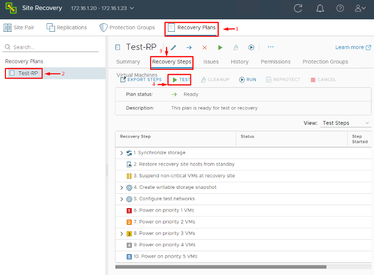
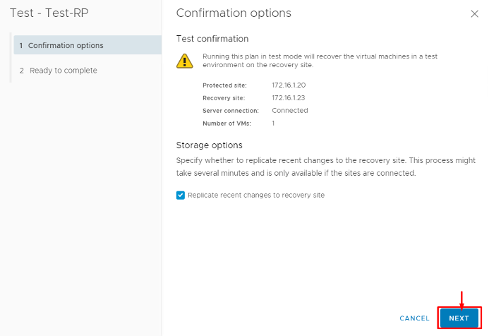
1. Initiate a Test Recovery: In the SRM interface, select your Recovery Plan and click the Test button (often found in the toolbar or via right-click > Test). A wizard will start for the test. SRM will ask whether you want to replicate recent changes before testing. If you choose Yes, SRM will do a last-minute sync of any pending writes from the protected site to the recovery site (this essentially simulates a Planned Migration where we assume we have time to gracefully sync everything). If you choose No, the test will proceed with whatever data was last replicated (simulating an abrupt disaster with potential data loss of recent changes).
2. Run the Test Failover: Once you proceed, SRM will execute the Recovery Plan in Test Mode. You’ll see steps being carried out in the SRM UI. What happens under the hood is:
-
- The protected VMs (if this were a real planned failover) would be gracefully shut down and a final sync done (if you chose that option).
- The recovery site then creates shadow VMs from the placeholders by attaching the replicated disks to them.
- The VMs at the DR site power on in the order defined by the plan, but connected to the isolated Test network (so they won’t interfere with production). Thanks to network mappings, their NICs get connected to that test VLAN automatically.
- You can then verify the VMs are running in test. Perhaps you RDP or SSH into some, run application smoke tests, etc., all in the isolated network.
Meanwhile, the original VMs at the primary site remain powered off (if it was a planned test) or remain unaffected and online (if you ran the test as an unplanned scenario without powering them off or syncing, SRM actually by default will not power off live VMs during a test; it uses the last snapshot of data).
3. End the Test and Cleanup: After confirming that the recovery plan ran successfully and the VMs on the DR side came up as expected (in their test bubble), you will stop the test. In the SRM interface, you would click Stop or Finish Test, which then prompts for Cleanup. Cleanup is an essential step – SRM will not consider the test complete (and will not allow you to run another test or a real failover) until cleanup is done. During cleanup, SRM takes all those test VMs it powered on and shuts them down, deletes the test snapshots, and resets everything to the pre-test state. It basically reverts to the placeholder state and confirms that the recovery plan is back in “Ready” status. As VMware’s documentation emphasizes, you must complete the cleanup operation before you can run another test or an actual failover. In the SRM UI, the Recovery Plan will return to “Ready for Recovery” once cleanup finishes.
Why is cleanup mandatory? Think of it this way: you had VMs running in DR site (test bubble) using replicas of the data. You need to dispose of those and unlock the replication for normal operation again. Cleanup also clears any record that a test was in progress. Skipping it would confuse SRM’s state tracking. So never skip cleanup; always let it run to completion.
At this point, you have performed a complete DR test without impacting production. Your primary site VMs are still running normally (assuming you did an unplanned-style test). The recovery site had the VMs running in isolation for validation, and now it’s been reset.
Tip: It’s good practice to schedule regular DR tests (e.g., quarterly or bi-annually) and document the outcomes for compliance. SRM makes it easy to test; there’s really no excuse not to!
If an actual disaster occurs, the process is similar except you would hit the Recovery (not Test) button. An actual Recovery can be done in two modes: Planned Migration (if both sites are up and you want to minimize data loss – it will sync then failover) or Disaster Recovery (if the primary site is abruptly down – it will just failover with whatever data is on the DR side). In either case, SRM will execute the steps to bring up VMs on the recovery site for real. Those VMs will connect to the normal production networks (since in a real recovery, we don’t use the test bubble network).
After a real failover, the roles of the sites are essentially swapped (the recovery site is now running the workloads). SRM provides a Reprotect option, which you would run once your original site is repaired and you’re ready to configure failback. Reprotect takes the VMs that are now running at the DR site and sets up replication in the reverse direction (DR back to primary). Once reprotection (reverse replication) is complete, you can execute the Recovery Plan again, this time in the reverse direction, to fail the workloads back to the original site. This failback process is essentially a mirror image of the failover you initially performed. (Note: Always ensure you have resolved whatever caused the original outage and that both sites have SRM/vCenter up before attempting a failback. Also, as of SRM 9.0, check release notes for any known issues with failback. For example, one early 9.0 bug required recreating protection groups for failback in some cases—patches have addressed issues like this in later updates.)
Conclusion
Setting up a robust disaster recovery site with VMware SRM 9.0 is straightforward when broken down into steps: pair the sites, configure your mappings (compute, network, storage) and placeholders, set up replication for your VMs, define Protection Groups, and create a Recovery Plan. Finally, always test your plan (and clean up) so that you’re prepared for the real thing.
The core workflow in SRM 9.0 remains similar to earlier versions of SRM, which means if you’re familiar with SRM 8.x, you’ll feel right at home. The enhancements in the new SRM 9.0 release mostly improve scalability and integration. Notably, SRM 9.0 supports up to 1,500 VMs per protection group and larger overall limits, accommodating larger environments than before. VMware has also introduced integration with the VMware Aria suite – there’s now an Aria Automation Orchestrator plug-in for SRM 9.0 and an Aria Operations management pack for SRM to extend automation and monitoring of your DR setup. These are great for advanced users who want to, say, trigger SRM failovers as part of a broader workflow or get deeper insights into DR health.
By following the steps outlined in this guide, you can confidently build and validate your disaster recovery plan. SRM takes care of the heavy lifting during an outage, coordinating the failover with precision. When the unexpected happens – be it a power outage, natural disaster, or even a planned data center maintenance – you’ll be ready to hit that “Failover” button. With VMware SRM 9.0 handling the orchestration, DR becomes a controlled, automated procedure rather than a frantic scramble. Your organization stays resilient, and you (the IT admin) get to be the hero who kept everything running smoothly even when disaster struck. Happy DR planning!
