Heartbeat is a technology that allows avoiding the so-called “split-brain” scenario when the HA cluster nodes are unable to synchronize but continue to accept write commands from the initiators independently. It can occur when all synchronization and heartbeat channels disconnect simultaneously, and the partner nodes do not respond to the node’s requests. As a result, StarWind service assumes the partner nodes to be offline and continues operations on a single-node mode using data written to it.
If at least one heartbeat link is online, StarWind services can communicate with each other via this link. The device with the lowest priority will be marked as not synchronized and get subsequently blocked for the further read and write operations until the synchronization channel resumption. At the same time, the partner device on the synchronized node flushes data from the cache to the disk to preserve data integrity in case the node goes down unexpectedly. It is recommended to assign more independent heartbeat channels during replica creation to improve system stability and avoid the “split-brain” issue.
With a heartbeat failover strategy, the storage cluster will continue working with only one StarWind node available.
To configure the Heartbeat Failover Strategy, perform the following actions:
1. Open Add Device Wizard in one of the following ways:
- Right-click a StarWind server and select Add Device (advanced) from the shortcut menu.
- Select a StarWind server and click the Add Device (advanced) button on the toolbar.
2. As Add Device Wizard appears, follow the instructions to complete creation of a new Image device.
3. Select Hard Disk Device as the type of a device to be created.
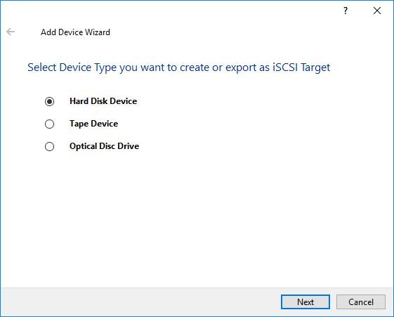
4. Click Next to continue.
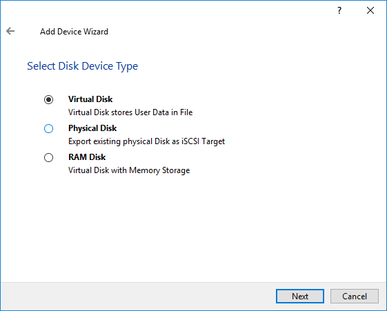
5. Click Next to continue.
6. Specify a virtual disk location and create a new file if required.
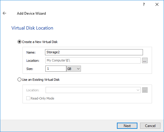
7. Click Next.
8. Select virtual disk options:
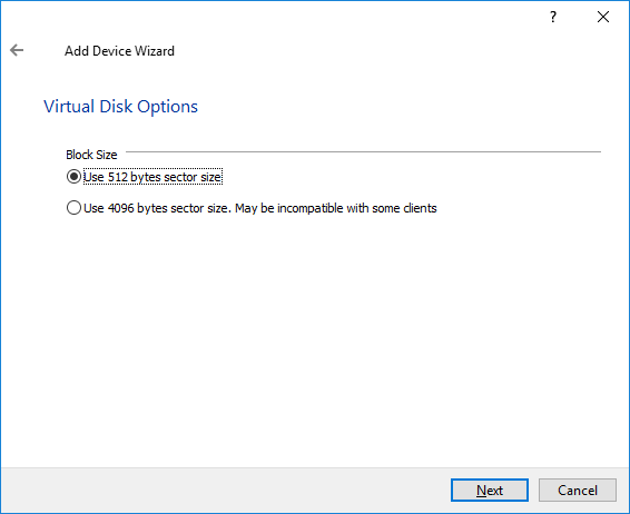
9. Click Next to continue.
10. Define the caching policy and specify the cache size (in MB).
The maximum available cache size can be set by selecting the appropriate checkbox.
NOTE: More information can be found in KB article: https://knowledgebase.starwindsoftware.com/explanation/starwind-virtual-san-l1-and-l2-caches-operational-principles/
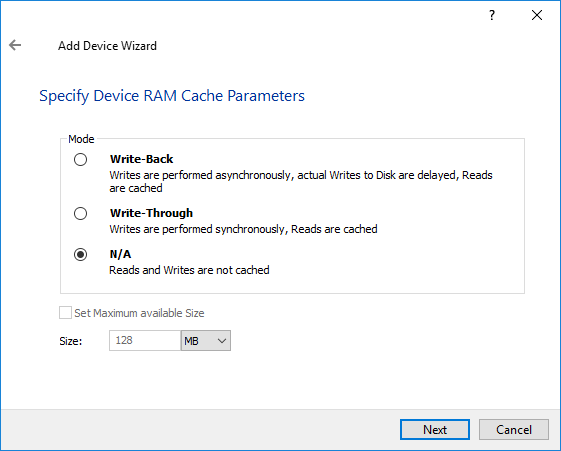
11. Click Next to continue.
12. Define the L2 caching policy and the cache size.
Note: L2 cache can be used with flat storage devices for performance acceleration of read operations. Use SSD drives to enable the L2 cache.
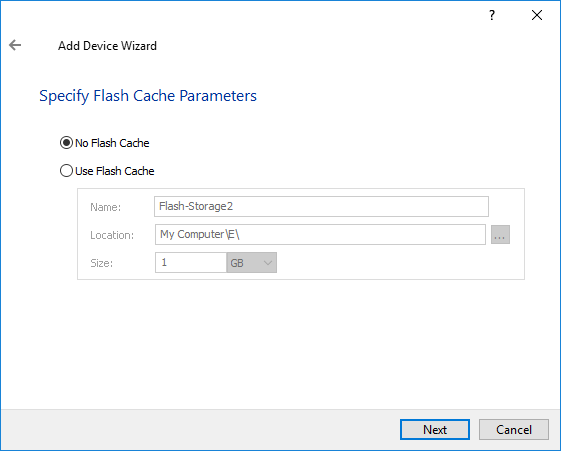
13. Click Next to continue.
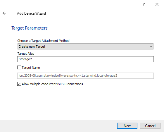
14. Specify target parameters.
Select a method of target attachment and fill in the Target Alias text field.
Select the Target Name checkbox to enter a custom name of a target. Otherwise, the name is generated automatically in accordance with the specified target alias.
Note: Specifying a reasonable name and alias simplifies navigation through the available iSCSI targets.
Select the Allow multiple concurrent iSCSI Connections checkbox if you want to enable several clients to connect simultaneously to the target.
15. Click Next to continue.
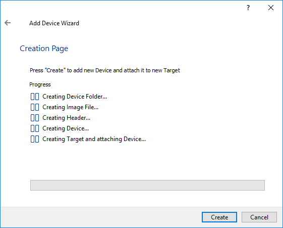
16. Click Create to add a new device and attach it to the target.
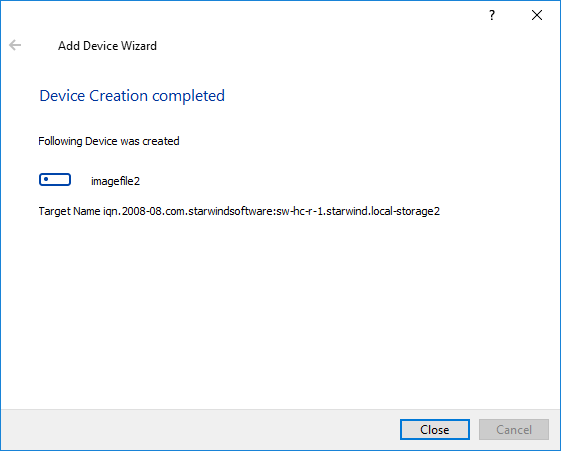
17. Click Close to close the wizard.
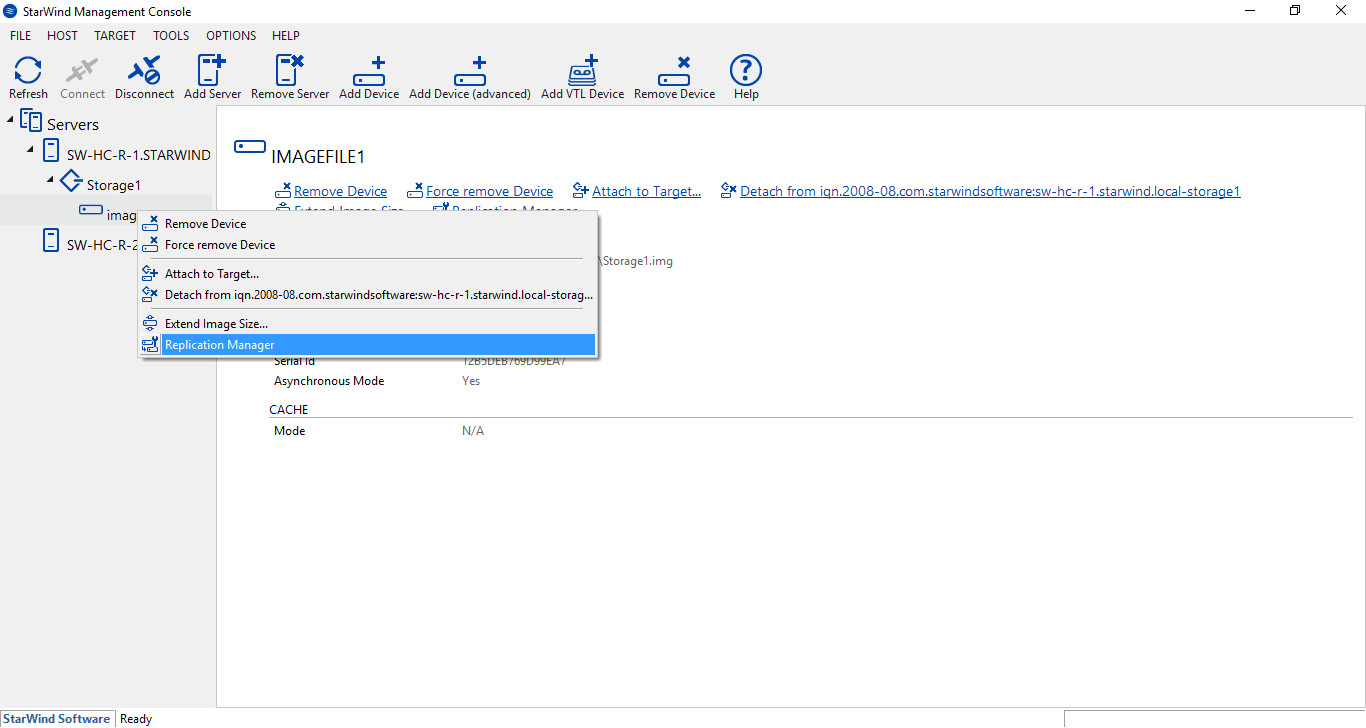
18. Right-click the needed device and select Replication Manager from the shortcut menu.
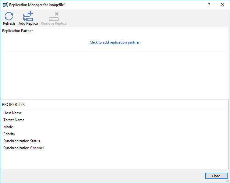
19. Then, click Add Replica.
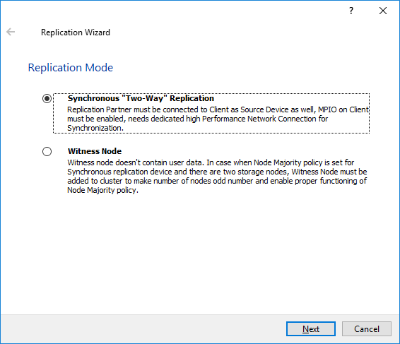
20. Select Synchronous "Two-Way" Replication as a replication mode and Next to proceed.
21. Specify a partner hostname, IP address, and port number.
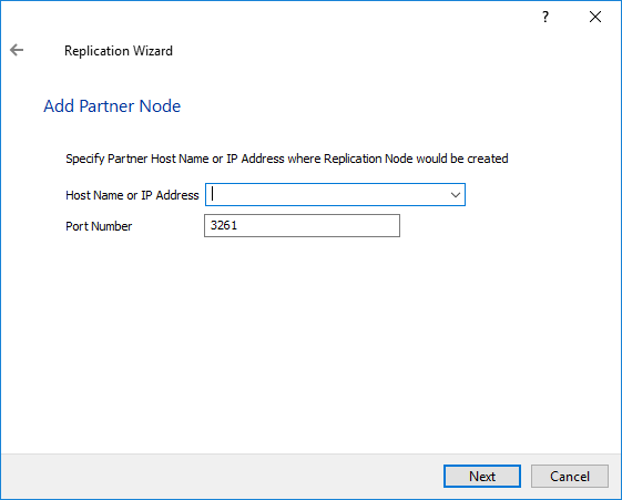
22. Click Next.
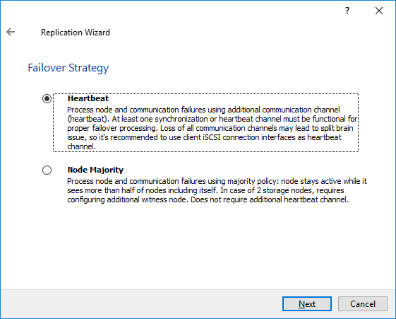
Note: Learn more about the difference between Heartbeat and Node Majority Failover Strategies.
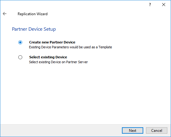
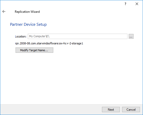
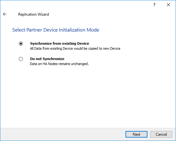
23. Select the Partner device setup and click Next.
24. You can modify the target name if required. Click Next.
25. Select Synchronization Journal Strategy and click Next.
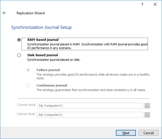
There are several options – RAM-based journal (default) and Disk-based journal with failure and continuous strategy, that allow to avoid full synchronization cases.
RAM-based (default) synchronization journal is placed in RAM. Synchronization with RAM journal provides good I/O performance in any scenario. Full synchronization could occur in the cases described in this KB: https://knowledgebase.starwindsoftware.com/explanation/reasons-why-full-synchronization-may-start/
Disk-based journal placed on a separate disk from StarWind devices. It allows to avoid full synchronization for the devices where it’s configured even when StarWind service is being stopped on all nodes.
Disk-based synchronization journal should be placed on a separate, preferably faster disk from StarWind devices. SSDs and NVMe disks are recommended as the device performance is defined by the disk speed, where the journal is located. For example, it can be placed on the OS boot volume.
It is required to allocate 2 MB of disk space for the synchronization journal per 1 TB of HA device size with a disk-based journal configured and 2-way replication and 4MB per 1 TB of HA device size for 3-way replication.
Failure journal – provides good I/O performance, as a RAM-based journal, while all device nodes are in a healthy synchronized state. If a device on one node went into a not synchronized state, the disk-based journal activates and a performance drop could occur as the device performance is defined by the disk speed, where the journal is located. Fast synchronization is not guaranteed in all cases. For example, if a simultaneous hard reset of all nodes occurs, full synchronization will occur.
Continuous journal – guarantees fast synchronization and data consistency in all cases. Although, this strategy has the worst I/O performance, because of frequent write operations to the journal, located on the disk, where the journal is located.
26. Click Change Network Settings.
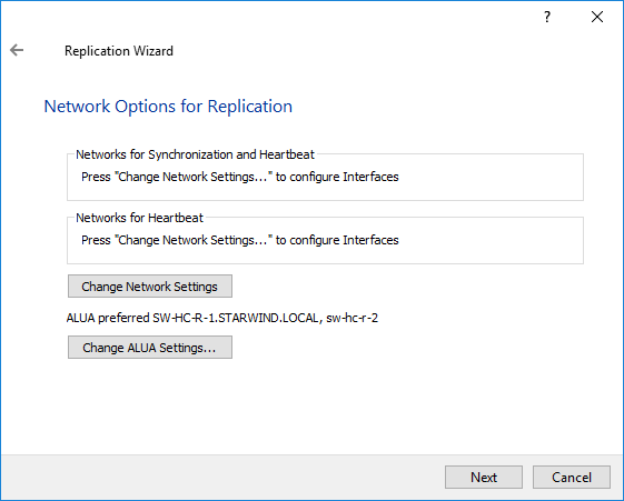
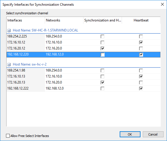
27. Specify interfaces for Synchronization and Heartbeat channels.
Note: At least one Heartbeat channel must be separated from a synchronization channel due to availability considerations.
28. Click Next.
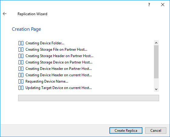
29. Click Create Replica.
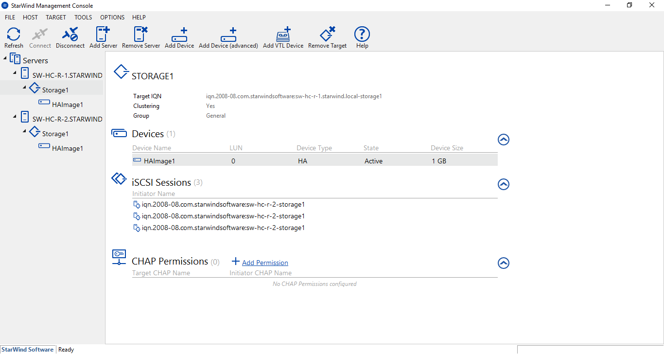
30. The successfully added devices appear in the StarWind Console.
To create StarWind HA Device with PowerShell script, please follow the next steps:
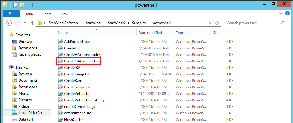
1. Open the folder containing StarWind PowerShell samples.
By default, samples are located under the path:
C:\Program Files\StarWind Software\StarWind\StarWindX\Samples\powershell.
2. Locate the file named CreateHA(two nodes).ps1 and copy it to any other place for further editing.
3. Open the file CreateHA(two nodes).ps1 file with PowerShell ISE (or any other text editor) and change the values marked with red.
4. For the first StarWind node:
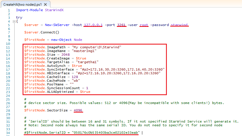
- host; Enter the IP address of the host that has StarWind service installed;
- port; Enter the StarWind service connection port number (3261 by default);
- user and password; Enter the StarWind username and password (default values are: username: root, password: starwind);
- firstNode.ImagePath; Enter the path to an existing directory where image file will be located;
- firstNode.ImageName; Enter an image file name;
- firstNode.Size; Enter an image file size in megabytes;
- firstNode.CreateImage; Create an image file.
NOTE that firstNode.CreateImage value should be equal to $true;
- firstNode.TargetAlias; Enter the alias of the target;
- firstNode.AutoSynch; Make sure to specify automatic or manual synchronization after device creation by setting the value of this variable to either $true or $false;
- firstNode.SyncInterface; Synchronization interfaces. Enter the IP address(s) of the partner node interface(s) (the “second” StarWind node) which will be used as the synchronization channel;
- firstNode.HBInterface; Heartbeat interfaces. Enter the IP address(s) of the partner interface(s) (the “second” StarWind node) which will be used as the heartbeat channel;
- firstNode.CacheSize; Enter the L1 cache size in megabytes or leave it as “” in case you would like it to be N/A;
- firstNode.CacheMode; Caching mode (“none” - without caching, “wt” – write-through mode or “wb” - write-back mode). Enter the necessary value;
- firstNode.PoolName; Enter the pool name in case you would like your resource to be tagged in SMI-S provider. Enter leave it as “” in case you do not need to tag your resources to the SMI-S provider;
- firstNode.SyncSessionCount; Synchronization session count. Make sure you set the value of the variable to “1”;
- firstNode.ALUAOptimized; Set ALUA optimization by entering $true or $false values.
- firstNode.SectorSize; Enter device sector size (512 for ESXi or 4096 for Hyper-V, SOFS);
- firstNode.SerialID; Comment out this line.
5. For the second StarWind node:
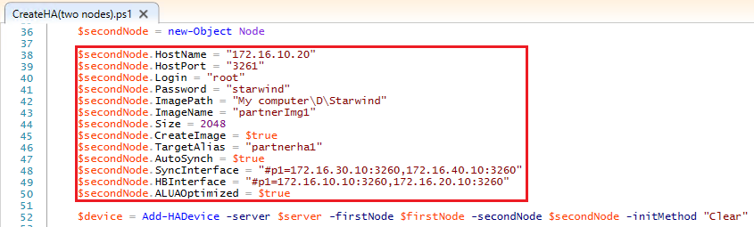
- secondNode.HostName; Enter a the IP address of a host where StarWind service is running;
- secondNode.HostPort; Enter the number of a port for connecting to the StarWind Service (3261 by default);
- secondNode.Login and secondNode.Password; Enter StarWind username and password (default values are: username: root, password: starwind);
- secondNode.ImagePath; Enter the path to an existing directory where image file will be located on the partner node (second node);
- secondNode.ImageName; Enter an image file name;
- secondNode.Size; Enter an image file size in megabytes. Note that is has be equal to the value of firstNode.Size;
- secondNode.CreateImage; Create an image file. Note that secondNode.CreateImage value should be equal to $true;
- secondNode.TargetAlias; Enter the alias of the target;
- secondNode.AutoSynch; Make sure to specify automatic or manual synchronization after device creation by setting the value of this variable to either $true or $false;
- secondNode.SyncInterface;
- Synchronization interfaces. Enter the IP address(es) of the partner node interface(s) (the “first” StarWind node) which will be used as the synchronization channel;
- secondNode.HBInterface; Heartbeat interfaces. Enter the IP address(es) of the partner node interface(s) (the “first” StarWind node) which will be used as the heartbeat channel;
- secondNode.ALUAOptimized; Set ALUA optimization by entering $true or $false values.
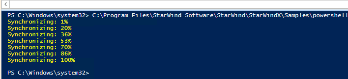
6. Run the script. After the HA device creation you should see the following:
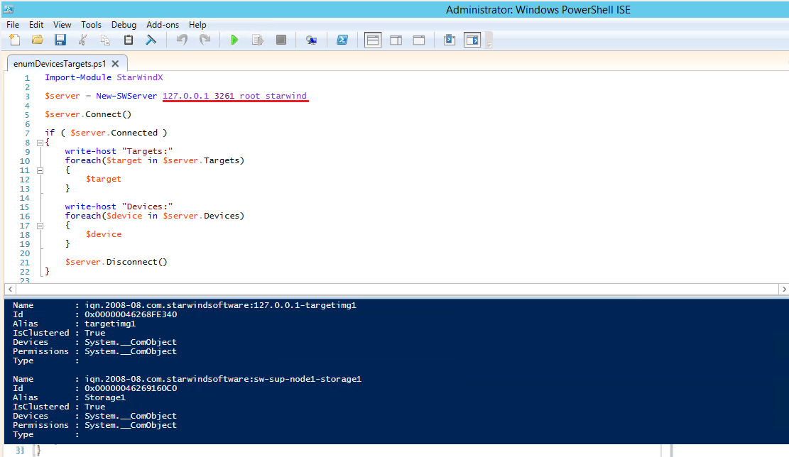
7. In order to list all the devices and targets on the StarWind host, run the enumDevicesTargets.ps1 script.
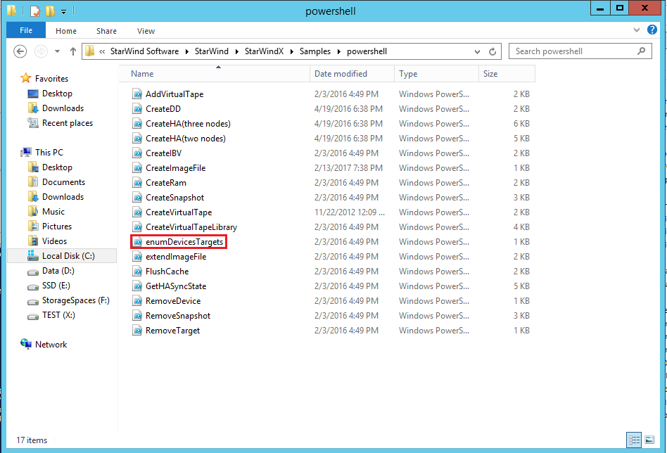
8. Make sure you modify the values marked with a red line in order to fit your setup (host IP, port, user, password), save the script and run it.