
Introduction
Previously, I shared my experience with certain problems with NIC Load Balancing on ESXi host and how they can be solved with ESXCLI. Some of my colleagues have been asking me what the difference between several types of load balancing and which one is better for use is. So, now I’m sharing my thoughts about concepts of network environment load balancing on the infrastructure level.
For starters, let’s refresh our memory regarding what Load Balancing is all about. Well, first of all, you don’t want to confuse load balancing network traffic with balancing workloads for optimal performance (that’s what DRS (Distributed Resource Scheduler) does). Carrier aggregation technology from VMware can combine two or more NICs into one data channel to increase the bandwidth of vSphere virtual switch or a group of ports, thereby enhancing the reliability of said channel. By configuring the failover procedure, you can choose how exactly traffic will be redirected in case of a failure of one of the NICs. Configuring the load balancing policy enables you to decide how exactly a vSwitch is going to load balance the traffic between NICs.
The conclusion is simple. This is a technology that unites physical interfaces into a logical one. Although aggregation allows increasing channel bandwidth, you shouldn’t really count on perfect load balancing between all interfaces in the aggregated channel. To put it simply, load balancing enables you to distribute traffic from virtual machines to vSwitches to pNICs. Whether it would be a vSwitch, pNIC, or a group of vNICs, there are several primary ways to load balance traffic:
- Route based on originating port ID
- Route based on IP hash
- Route based on source MAC hash
- Route Based on Physical NIC Load
- Use explicit failover order
Let’s dig into details.
Route based on originating port ID
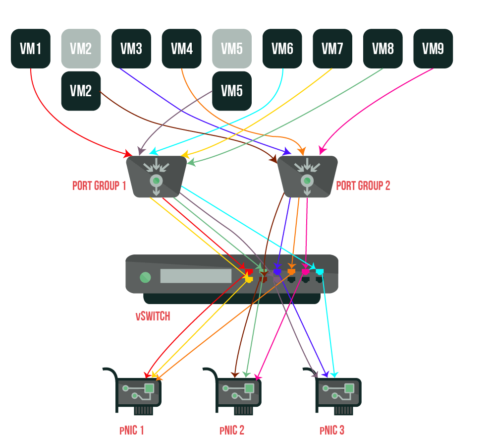
Load Balancing option based on the virtual port ID on the switch. This method is a default choice for standard and distributed vSwitches. It selects an uplink port accordingly to the number of the virtual port on vSwitch. One vNIC can use only one pNIC at a time.
This mode works following the next algorithm. Each virtual machine from the host has its own identifier on vSwitch. In order to assign an uplink port for a virtual machine, vSwitch uses a similar port identifier on a network card or a group of network cards. When an uplink port is assigned, vSwitch distributes traffic for a virtual machine through the same uplink port as long as this virtual machine works on that switch.
The virtual switch assigns the uplink port only once, a port identifier for a virtual machine is fixed, so if vSwitch assigns a different group of ports to the virtual machine, it generates a new uplink port.
Now, if you’re migrating, turning off your virtual machine, or deleting it, its port identifier on vSwitch becomes available once again. Furthermore, vSwitch stops sending traffic to this port, which, in turn, lowers overall traffic distributed to the uplink port connected with it. However, if the virtual machine is turned on or transferred, it may appear on another port and start using another uplink port.
If all pNICs in the group are active, they distribute traffic for a virtual machine.

Let’s see, if you turn off VM 2 and VM 5, then turn on in the following order VM 8, VM 9, VM 2, and VM 5, you’ll see that port identifier on Port Group 1 and Port Group 2 didn’t lose connection with pNIC uplink ports. In turn, VM 8 and VM 9 were connected to the uplink ports previously used by VM 2 and VM 5.
Pros:
- Simple physical switch configuration. Uplink binding (EtherChannel) isn’t necessary. Only independent ports of the switch require configuration;
- Supports equal distribution if the amount of vNICs surpasses the amount of pNICs;
- Physical NIC redundancy. Even if all pNICs are in active use, when one pNIC fails, the other pNICs in the team continue to balance traffic;
- Physical NIC group traffic can be balanced between several physical switches to preserve hardware failure;
- This load balancing type may use network failover detection mechanism that is called beacon probing;
- In the environment with several virtual machines, the load is balanced between all active network cards to increase performance.
Cons:
- One vNIC cannot use bandwidth from more than one pNIC. For example, if there are four pNICs in a group, 1 Gb/s each, a virtual machine with one vNIC cannot use more than 1Gb/s bandwidth through one pNIC;
- It’s not an appropriate pick for the virtual servers that work over a lot of requests from different clients when there’s a necessity to load balance traffic of one virtual machine (with one vNIC) between several pNICs;
- This mechanism won’t let you use 802.3ad channel aggregation technology. Moreover, you may also have trouble accessing IP- storage (iSCSI, NFS) since VMkernel can also use only one pNIC to work with different iSCSI-targets.
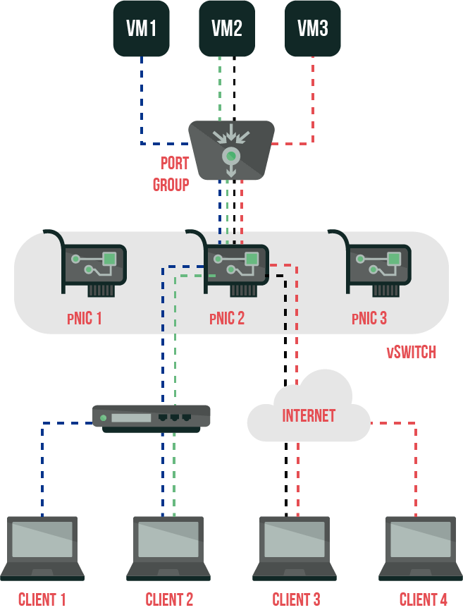
Route based on IP hash
This load balancing method is balancing traffic by creating a hash (fixed-size value) between the source IP address and destination IP packet. That way, traffic between one virtual machine and several clients, including through router, can be balanced with different vmNICs. To make this happen, you’ll need to turn on 802.3ad support on the physical switch connected to ESX Server. This load balancing option is the most efficient and the most complicated algorithm accordingly. Still, it may also cause the biggest load on the server since its there where hashes of IP addresses for each IP packet are calculated. IP
address hashing is calculated basing on the XOR algorithm with the following formula:
|
1 |
<em>((LSB (SrcIP) xor LSB (DestIP)) mod (# pNICs)</em> |
Load balancing equitability depends on the amount of TCP/IP-sessions between a host and different clients, also pNIC. With a large number of connections, this option allows balancing traffic more equally and doesn’t have disadvantages inherent to the option based on ID-port.
In case the host is connected to more than one switch, this method requires you to aggregate all ports of the physical switch into a stack (EtherChannel). If the physical switches don’t support such a work mode, you won’t be able to use this load balancing algorithm. This often can mean that you’ll have to connect all pNICs in vSwitch to one physical switch.
Just remember: if you really do have to connect all pNICs to one physical switch, – when it fails, all this system behind it fails as well.
While applying IP Hash as a load balancing algorithm, you’ll need to perform configuration on vSwitch, and you don’t have to override it on the ports group level. In other words, ALL devices connected to vSwitch with IP Hash load balancing should use IP Hash load balancing.
To exploit IP Hash load balancing to its maximum, you’ll need a source with a lot of destinations, or you’re risking encountering a situation when two or more requests instead of balancing will try to load the same pNIC.
Let’s assume that there is a VM that uses iSCSI-connected disk from 2 SANs. If these 2 SANs have IP addresses that can be calculated with the same module value (look at the tab), then all traffic will load one pNIC, which, in turn, lowers the efficiency of using IP Hash load balancing to a minimum.
| VM | IP VM | DestrIP | XOR (SrcIP, DestIP) | Modul | pNIC |
| VM 1 | x.x.x.10 | z.z.z.20 | (10 xor 20) = 30 mod 2 = 0 | 0 | 1 |
| VM 1 | x.x.x.10 | z.z.z.30 | (10 xor 30) = 20 mod 2 = 1 | 0 | 1 |
You can find more about this load balancing option here.
Pros:
- Increasing performance in cases when a VM communicates with several VMs. Theoretically, a virtual machine can use a bigger bandwidth than a pNIC can support;
- Physical NIC redundancy: in case of pNIC or uplink failure, the remaining NICs in the group will continue to balance traffic. ESXi host and physical switch must recognize the channel as inactive so that the uplink could work properly. If there is any inconsistency, traffic won’t be able to switch to the other pNICs in the group.
Cons:
- Physical switch configuration is less flexible and requires that the ports of the switch were configured for EtherChannel static connection. You can use only one switch for the pNICs group since most switches don’t support EtherChannel between several physical switches.
Please note. Of course, there are exceptions. Specific stacks or module switches actually can do that on several switches or modules. Cisco vPC (Virtual Port Channel) also can solve this problem, provided that switches support this technology. Talk to the vendor to get more information.
- This load balancing options doesn’t support Beacon probing. As a tool of detecting errors you can use only uplink port failure notification.
Route based on source MAC hash
Now, this scenario suggests that vSwitch selects an uplink port for a VM based on MAC-address of VM. To calculate an uplink port for VM, vSwitch applies LSB (Least Significant Bit) of the source MAC-address (vNIC MAC-address) according to the module of the amount of active pNICs in vSwitch to receive an address in pNIC array.
Let’s take, for example, the following scenario with 2 pNICs. Assuming the MAC-address of vNIC is 00:15:5D:99:96:0B, the LSB equals 0x0B or 11 in the decimal system. In modulo operation, you split (using integer division) LSB MAC in the amount of pNIC (11 / 3), and pick the remainder (in this case, 2) as the modulus of the operation. Physical NIC array is based on 0, which means that 0=pNIC 1, 1=pNIC 2, 2=pNIC 3.
If we were to take a look at the scenario with 6 virtual machines that have coherent MAC-addresses (at least, LSB is coherent), we would wind up in the following situation:

| name | MAC LSB | modul | pNIC |
| VM 1 | :39 = 57 | 0 | 1 |
| VM 2 | :6D = 109 | 1 | 2 |
| VM 3 | :0E = 14 | 2 | 3 |
| VM 4 | :5A = 90 | 0 | 1 |
| VM 5 | :97 = 151 | 1 | 2 |
| VM 6 | :F5 = 245 | 2 | 3 |
| VM 7 | :A2 = 162 | 0 | 1 |
Pros:
- More or less equal load balancing, comparing to routing based on originating port ID, since vSwitch calculates an uplink port for each packet;
- All VMs use the same uplink port because MAC-address is static. Turning the virtual machine on and off doesn’t affect its uplink port assignment;
- No changes on physical switch are required.
Cons:
- The speed of the uplink port connected to the respective port identifier defines the bandwidth available for the virtual machine unless the VM is using several vNICs with different MAC-addresses;
- Higher than routing consuming resources which is explained by the fact that vSwitch calculates uplink ports for each packet;
- The virtual switch isn’t monitoring uplink ports current load, which is why they may become overloaded.
Route Based on Physical NIC Load
This load balancing method is available only for distributed switches. Mostly, it reminds our first option, namely routing based on originating port ID. However, there are also differences, and they are significant enough. First of all, while choosing which pNIC will balance traffic, the choice is not random but defined depending on the load on this pNIC. Further, the selection frequency is 30 seconds (in the other vSwitch options, once you have chosen port identifier for pNIC, it stays that way until the VM is on). If the load exceeds 75%, the VM port identifier with the highest value of I/O operations switches to another uplink port of another pNIC.
To put it simply, this algorithm basically doesn’t use load balancing at all, however ironic it may sounds. It looks like a failover scenario and uses the most available uplink port from the list of active pNICs for all traffic.
Pros:
- Low resource consumption, since distributed switch only calculates uplink port for the VM once, and checking uplinks affects it minimally;
- A distributed switch is monitoring uplink port load and lowers it whenever it is possible;
- No changes on physical switch are required.
Cons:
- The uplink port connected to the respective distributed switch defines the bandwidth available for the virtual machine.
Use explicit failover order
Now, this may be surprising. This policy makes an actual load balancing virtually impossible. The thing is, vSwitch always employs the highest uplink port in the list of the available active NICs. If you’re unable to use the first uplink port in the list, you can use the second on the list, and so on. The failover order parameter defines the uplink port. This parameter defines Active/Standby pNIC mode to the vSwitch.
Conclusions
In general, every Load Balancing policy has both its pros and cons. What option to choose depends on what do you need to do. If you’re not experienced in these matters, I would strongly advise you to begin with the method based on originating port ID, the default option. Furthermore, with more understanding of the process, you can switch to whatever suits you most.
I hope this topic is more clear for you now, and if you’re looking for more details, you’re welcome to check VMware guides. Please note that this material is introductory, so if you’ll think of a way to improve it – let me know!
